Observation of magnon cross-Kerr effect in cavity magnonics
Abstract
When there is a certain amount of field inhomogeneity, the biased ferrimagnetic crystal will exhibit the higher-order magnetostatic (HMS) mode in addition to the uniform-precession Kittel mode. In cavity magnonics, we show both experimentally and theoretically the cross-Kerr-type interaction between the Kittel mode and HMS mode. When the Kittel mode is driven to generate a certain number of excitations, the HMS mode displays a corresponding frequency shift, and vice versa. The cross-Kerr effect is caused by an exchange interaction between these two spin-wave modes. Utilizing the cross-Kerr effect, we realize and integrate a multi-mode cavity magnonic system with only one yttrium iron garnet (YIG) sphere. Our results will bring new methods to magnetization dynamics studies and pave a way for novel cavity magnonic devices by including the magnetostatic mode-mode interaction as an operational degree of freedom.
I INTRODUCTION
Nonlinear effects are a large class of physical phenomena that have been continuously and actively explored in optics Boyd ; Autere2018 ; Zhang2019 , plasmonics Kauranen2012 ; Mesch2016 ; Zhong2020 , and acoustics Hamilton1998 ; Fang2017 ; Darabi2019 , as well as in other oscillations and wave systems Nayfeh2008 ; Kartashov2019 ; Zuo2020 . Nonlinearity and nonlinear interactions are weak and difficult to be detected in some systems, but they can also become sufficiently strong to be the dominant factor in some other systems. The cross-Kerr effect is one of the subtle nonlinear interactions between fields and waves that can exist in natural ions Ding2017 , atoms He2014 ; Xia2018 ; Sinclair2019 , and artificial mesoscopic architectures, such as superconducting circuits Hoi2013 ; Kounalakis2018 ; Vrajitoarea2020 . The cross-Kerr effect is a nonlinear shift in the frequency of a resonator as a function of the number of excitations in another mode that interacts with the resonator. Understanding these nonlinear interactions is not only of fundamental importance, but also useful in various applications. In practice, the cross-Kerr effect can be utilized to implement quantum logic gates Turchette1995 ; Brod2016 , prepare entangled photons Lukin2000 ; Sheng2008 , and carry out quantum non-demolition measurements Wang2019 ; Dassonneville2020 .
Cavity magnonics, on the other hand, has gradually demonstrated its unique advantages in fundamental and applied research over the last few years Huebl2013 ; Tabuchi2014 ; Zhang2014 ; Goryachev2014 ; Bai2015 ; Cao2015 ; Zhang2015 ; Tabuchi2015 ; Haigh2016 ; Maier-Flaig2016 ; A.Osada2016 ; X.Zhang2018 ; Zhang2017 ; PuWang2018 ; A.Osada2018 ; JieLi2018 ; Harder2018 ; Y.P.Wang2019 ; Lachance-Quirion2020 ; Y.Yang2020 ; J.Xu2020 ; S.P.Wolski2020 ; Jinwei2021 ; Xufeng2021 ; Potts2021 ; D.Zhang2015 . It is expected to be a critical component of hybrid quantum systems LachanceQuirion2019 and quantum network nodes Jie2021 . The commonly used physical implementation of a cavity magnonic system consists of a microwave cavity and ferro-(ferri-)magnets, such as YIG. The spin collective excitation modes are spin waves in the ferrimagnetic spin ensemble. The most widely studied spin wave mode is the uniform precession mode of spins (i.e., the Kittel mode), which has the largest magnetic dipole moment and can strongly interact with the microwave in both the quantum limit Huebl2013 ; Tabuchi2014 and room-temperature classical regime Zhang2014 . Under the bias of an external magnetic field with certain inhomogeneity, besides the Kittel mode, there are also higher-order magnetostatic (HMS) modes in the spin ensemble J.F.Dillon1958 ; P.C.Fletcher1959 . Previous studies often ignored the influence of these magnetostatic modes on the observation and application of Kittel mode in experiments. However, the HMS modes actually have nontrivial spin textures. Their non-zero orbital angular momentum feature can be used to demonstrate nonreciprocal Brillouin light scattering in optomagnonics and other chiral optics A.Osada2018 ; J.Graf2018 ; J.A.Haigh2018 ; Osada_2018 . In the case of YIG sphere supporting optical whispering-gallery modes, the optomagnonic coupling strength can be enhanced for HMS modes due to their reduced mode volume and the localized distribution on the boundary J.Graf2018 ; A.Gloppe2019 , which increases the microwave-to-optical photon transduction efficiency in the cavity optomagnonic system.
In this work, we focus on the cavity magnonic system with the cross-Kerr interaction between the Kittel mode and HMS mode, used as a new control degree of freedom. This cross-Kerr interaction is investigated both theoretically and experimentally in a coupled 3D cavity and YIG sphere system, where the YIG sphere supports both the Kittel mode and HMS mode. A large frequency detuning between these two modes is found. When the Kittel mode or HMS mode is pumped to generate a certain number of magnon excitations, the pumped mode gains a frequency shift due to the self-Kerr effect PuWang2018 ; Y.P.Wang2016 ; GQ2019 ; Kong2019 ; Xiao2021 ; Ruichang2021 ; Gurevich2020 . Meanwhile, the frequency of the undriven mode also shifts due to the cross-Kerr effect between these two modes. Then, the ratio of the self-Kerr and cross-Kerr coefficients can be obtained. Furthermore, using the cross-Kerr coefficient as a ruler, we find that the magnetostatic mode’s self-Kerr coefficient is greater than that of the Kittel mode. This offers additional controllable degrees of freedom in cavity magnonics without increasing system’s complexity. Our study will also bring new ideas to the fundamental magnetostatics studies and hybrid magnonic operations Y.Li2020 ; B.Z.R ; Yuan .
II SYSTEM AND THEORETICAL MODEL
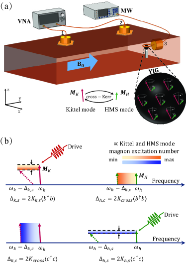
The experimental setup of the cavity magnonic system is illustrated in Fig. 1(a). It consists of the microwave field in a 3D copper cavity (internal dimension is 44.020.06.0 mm3 ), the magnon modes in a single crystal YIG sphere (1 mm in diameter), and the drive field provided by a microwave (MW) source. The YIG sphere is glued on the top of a beryllium ceramic rod and mounted at the antinode of the magnetic field of the cavity mode ( GHz). The whole sample is placed in a bias magnetic field applied along the crystal axis, which results in a negative self-Kerr coefficient PuWang2018 ; Gurevich2020 . The bias magnetic field, the magnetic field of the cavity mode , and the drive field magnetic component are perpendicular to each other at the position of the YIG sphere. This configuration maximizes the cavity-YIG coupling strength and drive efficiency. The drive field is loaded to port 3, which is terminated with a loop antenna. The vector network analyzer (VNA) is used for measuring the microwave transmission spectrum via port 1 and port 2. The probe power is much weaker than the drive power. It should be noted that the loop antenna plays multiple roles: (i) radiates the drive field; (ii) works as a dissipative channel for the magnon modes; (iii) creates an inhomogeneous magnetic field, which gives rise to the emergence of HMS modes.
Owing to the inhomogeneity of the magnetic field, apart from the Kittel mode, the HMS mode is also excited. The two modes are both supported by the collective spin motion. More spin moments contribute to the spin uniform precession mode (Kittel mode), yielding a large dipole moment for the Kittel mode. Therefore, the couplings between the Kittel mode and other electromagnetic fields are usually strong. However, fewer spin moments contribute to the dipole of the HMS mode, so the coupling between the HMS mode and cavity mode is weak in cavity magnonics LachanceQuirion2019 ; C.Zhang2021 . Both the Kittel mode and HMS mode are nonlinear modes on account of the magnetocrystalline anisotropy. The magnetocrystalline anisotropy energy measures the energy cost when tuning the magnetization orientation from the easy axis to the hard axis. Mathematically, the energy term is proportional to ( is the macrospin operator) and a self-Kerr term can be obtained, where is the Kerr coefficient and () is the creation (annihilation) operator of the magnon mode Y.P.Wang2016 ; GQ2019 . When the magnon mode is pumped to generate a certain number of excitations, the precession angle of the magnetization increases. This process leads to the change of the magnetocrystalline anisotropy energy, which results in the frequency shift of the nonlinear mode. In previous studies, the interaction between the Kittel mode and HMS mode has rarely been investigated. Here, we model the two magnon modes with two sub-magnetizations ( and ), which nonlinearly interact with each other. The interaction term is proportional to (subscript and represent the Kittel mode and HMS mode), which gives a two-mode cross-Kerr term. The total Hamiltonian of the coupled system is (see Appendix A)
| (1) |
where (), () and () are the creation (annihilation) operators of the cavity mode at frequency , the Kittel mode at frequency , and the HMS mode at frequency , respectively; and are the self-Kerr coefficients of the Kittel mode and HMS mode; is the cross-Kerr coefficient between the two magnon modes; () is the coupling strength between the Kittel (HMS) mode and cavity mode; is the coherent coupling strength between the Kittel mode and HMS mode (see Appendix A); () is the drive-field strength on the Kittel (HMS) mode, and is the drive-field frequency.
The observable effects of the self-Kerr and cross-Kerr effects are schematically illustrated in Fig.1(b). The drive field applied on the Kittel mode enlarges the precession angle of the magnetization , which also corresponds to the generation of a certain number of magnon excitations. In the case of Kittel mode with a negative self-Kerr coefficient and under the mean-field approximation, the frequency of the Kittel mode will have a red-shift PuWang2018 ; Ruichang2021 , equals to . Here the extra subscript represent the self-Kerr. Simultaneously, the cross-Kerr effect will also induce a frequency shift of the undriven HMS mode, and the precession angle of the magnetization is, however, unchanged. The frequency shift caused by the cross-Kerr effect is also proportional to the Kittel-mode magnon excitation number, which is . Here the latter subscript represents the cross-Kerr. A similar mechanism occurs when the drive field is applied solely on the HMS mode, as shown in the bottom panel of Fig. 1(b). It is worth mentioning that the scale ratios of the frequency shifts drawn in the figure are not set arbitrarily but roughly correspond to the experimental results discussed in the following section.
III EXPERIMENTAL RESULTS
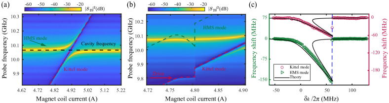
The transmission spectra of the coupled system are measured versus the magnet coil current as shown in Fig. 2(a). The large anti-crossing indicates the strong coupling between the Kittel mode and cavity mode, and the coherent coupling strength is 40.5 MHz. At the left part of the transmission mapping, when the magnet coil current is about 4.75 A, we find a small coupling feature, which is attributed to the HMS mode. The coupling strength is 2 MHz. The detuning between the Kittel mode and HMS mode is 301 MHz.
III.1 Drive the Kittel mode
In Fig. 2(b), we apply the drive field with a power of 25 dBm at the fixed frequency of 9.8 GHz on the Kittel mode and measure the transmission spectra versus the magnetic coil current. Typical bistable frequency jumps can be observed in both the Kittel mode and HMS mode, induced by the self-Kerr effect and cross-Kerr effect, respectively. This measurement is equivalent to sweeping the frequency of the drive field while fixing the frequencies of the magnon modes. We define the drive field detuning as . It should be noted that our system works in the double-dispersive regime, where and . The coherent couplings induced frequency shifts approximately equal and , respectively Y.P.Wang2016 ; GQ2019 . In the dispersive regime, they are all small terms. Also, the coupling strength between the HMS mode and cavity mode is relatively small. In this case, we can intently pay attention to the Kerr nonlinearity induced effects. Then we extract and plot the frequency shifts of the two magnon modes versus in Fig. 2(c). The driven Kittel mode has a maximum frequency shift of about -60 MHz, and the undriven HMS mode has a synchronous frequency shift of about -150 MHz.
The frequency shift of the driven Kittel mode can be fitted by the following equation Y.P.Wang2016 ; GQ2019 :
| (2) |
where MHz is the Kittel mode linewidth, is the coefficient of drive efficiency on the Kittel mode, and is the drive power. For the undriven HMS mode, the frequency shift can be fitted by . The fitting curves are shown as solid black lines in Fig. 2(c), which are in good agreement with the experimental results. We get the ratio of 2.5, which indicates that the cross-Kerr nonlinearity is 2.5 times larger than the self-Kerr nonlinearity of the Kittel mode.
III.2 Drive the HMS mode
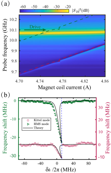
The cross-Kerr effect implies that the HMS mode excitation will also induce a frequency shift of the Kittel mode. Next, we apply the drive field (25 dBm) at a fixed frequency of 10.1 GHz on the HMS mode and sweep the magnetic field. The measured transmission mapping is shown in Fig. 3(a). As expected, the HMS mode has a frequency shift due to the self-Kerr effect, and simultaneously the cross-Kerr effect shifts the Kittel mode frequency. We extract the frequency shifts of these two modes versus the drive field detuning as shown in Fig.3(b). Similarly, the self-Kerr effect induced frequency shift of the HMS mode obeys the following equation:
| (3) |
where MHz is the HMS mode linewidth, is the coefficient of drive efficiency on the HMS mode. The frequency shift of the Kittel mode induced by the cross-Kerr effect can be further fitted by . The fitting curves are shown as black lines in Fig. 3(b). We get .
From the above two sets of experiments, we get , which shows that the HMS mode’s self-Kerr nonlinearity is five times larger than that of the Kittle mode. In any case, the cross-Kerr effect plays a vital role in the nonlinear process, and it acts as a ruler telling us the ratio between the nonlinear coefficients of different spin wave modes. More specifically, by comparing the amounts of the frequency shifts observed in the two sets of experiments where the drive powers are both 25 dBm, we can conclude that pumping the HMS mode is more challenging than pumping the Kittel mode with the same loop antenna, which may be caused by the small dipole moment of the HMS mode.
III.3 Stable feature under various drive frequencies
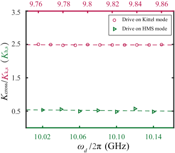
Finally, we carry out a series of experiments where the drive field frequency is changed. We measure the ratios of the cross-Kerr to the two self-Kerr coefficients. As shown in Fig.4, the ratios keep consistent at different drive field frequencies, which imply that the observed nonlinearity is the intrinsic property of this ferrimagnetic crystal. This stable feature provides more guarantees for the information conversion and storage among different modes in a single YIG sphere.
IV CONCLUSION
The cross-Kerr effect is an important nonlinearity, which describes the effect of excitations in one mode on another mode’s resonant frequency. In this work, we investigate the cross-Kerr effect in a ferrimagnetic spin ensemble, in which one Kittel mode and one higher-order magnetostatic mode co-exist. The cross-Kerr interaction between them plus their individual self-Kerr effects give rise to fascinating phenomena. In the experiment, we drive the Kittel model and the higher-order magnetostatic mode, respectively, and obtain the ratios between the cross-Kerr coefficient and their self-Kerr coefficients. Our experiment opens up a new path to study nonlinear effects in magnetic materials and spin ensembles. The mutual interaction between different magnetostatic modes in a single YIG sample can also provide new degrees of freedom for cavity spintronics and cavity magnonics Roadmap . We anticipate that this finding may stimulate more designs and applications of cavity magnonics.
Acknowledgements.
The authors thank Y. H. Li for helpful discussions. This work is supported by the National Natural Science Foundation of China (Grants No. 11934010, No. U1801661, and No. 12174329), Zhejiang Province Program for Science and Technology (Grant No. 2020C01019), the Fundamental Research Funds for the Central Universities (No. 2021FZZX001-02), and the China Postdoctoral Science Foundation (No. 2019M660137).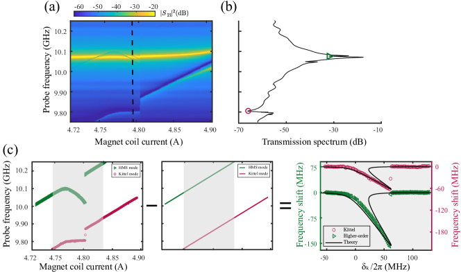
APPENDIX A INTERACTION BETWEEN THE KITTEL MODE AND HMS MODE
First, we derive the Hamiltonian of the magnon modes without including the cross-Kerr effect. Under the bias magnetic field , the Hamiltonian of the Kittel mode is written as (HMS mode has a similar form) Y.P.Wang2016
| (4) |
where the first term represents the Zeeman energy and the second term is the magnetocrystalline anisotropy energy. is the sub-magnetization corresponding to the Kittel mode. is the volume of the YIG sphere, is the vacuum permeability, and is the anisotropic field due to the magnetocrystalline anisotropy in the YIG crystal.
We adopt the direction of the bias magnetic as the direction (). When the [110] crystal axis of the YIG sphere is aligned along the bias magnetic field, the anisotropic field is given by stancil2009
| (5) |
where is the first-order magnetocrystalline anisotropy constant. Then, the Hamiltonian of the Kittel mode has the form
| (6) | |||||
By using the macrospin operator , where is the electronic gyromagnetic ratio Soykal2010 , the Hamiltonian can be written as
| (7) | |||||
We harness the Holstein-Primakoff transformation Holstein1940 : , , and , where is the total spin number, and . The excited magnon number is small compared with the total spin number , and the higher-order terms can be neglected in the Holstein-Primakoff transformation. In this case, we have and . Under the rotating-wave approximation, we finally obtain the Hamiltonian
| (8) |
where
and the value of can be found in Ref. stancil2009 .
For the interaction Hamiltonian between the Kittel mode and HMS mode, we consider these two modes as two sets of submagnetization, and the interaction between them can be written as
| (9) |
where is a coefficient that measures the mode overlapping between the Kittel mode and HMS mode. This mode overlap originates from the partial local spins shared by the Kittel mode and other spin wave modes A.Gloppe2019 ; stancil2009 . Under the Holstein-Primakoff transformation and rotating-wave approximation, we can get
| (10) |
The first and second terms produce constant frequency shifts in the Kittel mode and HMS mode, respectively. The third term refers to the coherent coupling between the Kittel mode and HMS mode. In our experiment, the detuning between the Kittel mode and HMS mode is sufficiently large, and the system is in the dispersive regime. If we tune the Kittel mode close to the HMS mode, we can predict level repulsion. A related effect has been observed in a previous study Paul .
The total Hamiltonian of the cavity magnonic system becomes
| (11) |
where and .
APPENDIX B DATA PROCESSING METHOD
The transmission spectrum mapping consists of a sequence of transmission spectra measured at different bias magnetic fields, as shown in Fig. 5(a). The individual transmission spectrum is depicted in Fig.5(b). The anti-resonances correspond to various modes; for example, the green triangle dot represents the HMS mode, and the circle red dot denotes the Kittel mode. We extract the data points from the sequence of transmission spectra and plot them in the left panel of Fig.5(c). To obtain a plot of frequency shift versus driving detuning that is easy to fit with our theoretical model, we subtract the linear component that increases with the external bias field from all data points. Then, the remaining component is the contribution of frequency shift caused by the driving field and Kerr effects. The middle panel of Fig. 5(c) depicts the linear frequency shift caused by the increased bias magnetic field. In order to fit the experimental data with Eq. (2), we replace the horizontal axis with drive detuning .
References
- (1) R. W. Boyd, Nonlinear optics (Academic press, London, 2020).
- (2) A. Auere, H. Jussila, Y. Dai, Y. Wang, H. Lipsanen, and Z. Sun, Nonlinear optics with 2d layered materials, Advanced Materials 30, 1705963(2018).
- (3) X. Zhang, Q.-T. Cao, Z. Wang, Y.-x. Liu, C.-W. Qiu, L. Yang, Q. Gong, and Y.-F. Xiao, Symmetry-breaking-induced nonlinear optics at a microcavity surface, Nature Photonics 13, 21 (2019).
- (4) M. Kauranen and A. V. Zayats, Nonlinear plasmonics, Nature Photonics 6, 737 (2012)
- (5) M. Mesch, B. Metzger, M. Hentschel, and H.Giessen, Nonlinear Plasmonic Sensing, Nano Letters 16, 3155 (2016)
- (6) J.-H. Zhong, J. Vogelsang, J.-M. Yi, D. Wang, L. Wittenbecher, S. Mikaelsson, A. Korte, A. Chimeh, C. L. Arnold, P. Schaaf, E. Runge, Anne L’ Huillier, A. Mikkelsen, and C. Lienau, Nonlinear plasmon-exciton coupling enhances sum-frequency generation from a hybrid metal/semiconductor nanostructure, Nature Communications 11, 1464 (2020).
- (7) M. F. Hamilton, D. T. Blackstock, Nonlinear acoustics, (Academic press, San Diego, 1998).
- (8) X. Fang, J. Wen, B. Bonello, J. Yin, and D. Yu, Ultra-low and ultra-broad-band nonlinear acoustic metamaterials, Nature Communications 8, 1288 (2017).
- (9) A. Darabi, L. Fang, A. Mojahed, M. D. Fronk, A. F. Vakakis, and M. J. Leamu, Broadband passive nonlinear acoustic diode, Phys. Rev. B 99, 214305 (2019).
- (10) A. H. Nayfeh and D. T. Mook, Nonlinear oscillations (John Wiley & Sons, New York, 2008).
- (11) Y. V. Kartashov, G. E. Astrakharchik, B. A. Malomed, and L. Torner, Frontiers in multidimensional self-trapping of nonlinear fields and matter, Nature Reviews Physics 1, 185 (2019).
- (12) Y. Zuo, W. Yu, C. Liu, X. Cheng, R. Qiao, J.liang, X. Zhou, J. Wang, M. Wu, Y. Zhao, P. Gao, S. Wu, Z. Sun, K. Liu, X. Bai, and Z. Liu, Optical fibres with embedded two-dimensional materials for ultrahigh nonlinearity, Nature Nanotechnology 15, 987 (2020).
- (13) S. Ding, G. Maslennikov, R. Habl’́utzel, and D. Matsukevich, Cross-Kerr Nonlinearity for Phonon Counting, Phys. Rev. Lett. 119,193602 (2017).
- (14) B. He, A. V. Sharypov, J. Sheng, C. Simon, and M. Xiao, Two-photon dynamics in coherent Rydberg atomic ensemble, Phys. Rev. Lett. 112, 133606 (2014).
- (15) K. Xia, F. Nori, and M. Xiao, Cavity-free optical isolators and circulators using a chiral cross-Kerr nonlinearity, Phys. Rev. Lett. 121, 203602 (2018).
- (16) J. Sinclair, D. Angulo, N. Lupu-Gladstein, K. Bonsma-Fisher, and A. M. Steinberg, Observation of a large, resonant, cross-Kerr nonlinearity in a cold Rydberg gas, Phys. Rev. Research , 033193 (2019).
- (17) I.-C. Hoi, A. F. Kockum, T. Palomaki, T. M. Stace, B. Fan, L. Tornberg, S. R. Sathyamoorthy, G. Johansson, P. Delsing, and C. M. Wilson, Giant Cross–Kerr Effect for Propagating Microwaves Induced by an Artificial Atom,Phys. Rev. Lett. 111, 053601 (2013).
- (18) M. Kounalakis, C. Dickel, A. Bruno, N. K. Langford and G. A. Steele, Tuneable hopping and nonlinear cross-Kerr interactions in a high-coherence superconducting circuit, npj Quantum Information 4, 38 (2018).
- (19) A. Vrajitoarea, Z. Huang, P. Groszkowski, J. Koch, and A. A. Houck, Quantum control of an oscillator using a stimulated Josephson nonlinearity, Nature Physics 16, 211 (2020)
- (20) Q. A. Turchette, C. J. Hood, W. Lange, H. Mabuchi, and H. J. Kimble, Measurement of Conditional Phase Shifts for Quantum Logic, Phys. Rev. Lett. 75, 4710 (1995).
- (21) D. J. Brod and J. Combes, Passive CPHASE Gate via Cross-Kerr Nonlinearities, Phys. Rev. Lett. 117, 080502 (2016).
- (22) M. D. Lukin and A. Imamoǧlu, Nonlinear Optics and Quantum Entanglement of Ultraslow Single Photons, Phys. Rev. Lett. 84, 1419 (2000).
- (23) Y. B. Sheng, F. G. Deng, and H. Y. Zhou, Efficient polarization-entanglement purification based on parametric down-conversion sources with cross-Kerr nonlinearity, Phys. Rev. A 77, 042308 (2008).
- (24) X. Wang, A. Miranowicz, and F. Nori, Ideal Quantum Nondemolition Readout of a Flux Qubit without Purcell Limitations, Phys. Rev. Applied 12, 064037 (2019).
- (25) R. Dassonneville, T. Ramos, V. Milchakov, L. Planat, É. Dumur, F. Foroughi, J. Puertas, S. Leger, K. Bharadwaj, J. Delaforce, C. Naud, W. Hasch-Guichard, J. J. García-Ripoll, N. Roch, and O. Buisson, Fast High-Fidelity Quantum Nondemolition Qubit Readout via a Nonperturbative Cross-Kerr Coupling, Phys. Rev. X 10, 011045 (2020).
- (26) H. Huebl, C. W. Zollitsch, J. Lotze, F. Hocke, M. Greifenstein, A. Marx, R. Gross, and S. T. B. Goennenwein, High Cooperativity in Coupled Microwave Resonator Ferrimagnetic Insulator Hybrids, Phys. Rev. Lett. 111, 127003 (2013).
- (27) Y. Tabuchi, S. Ishino, T. Ishikawa, R. Yamazaki, K. Usami, and Y. Nakamura, Hybridizing Ferromagnetic Magnons and Microwave Photons in the Quantum Limit, Phys. Rev. Lett. 113, 083603 (2014).
- (28) X. Zhang, C.-L. Zou, L. Jiang, and H. X. Tang, Strongly Coupled Magnons and Cavity Microwave Photons, Phys. Rev. Lett. 113, 156401 (2014).
- (29) M. Goryachev, W. G. Farr, D. L. Creedon, Y. Fan, M. Kostylev, and M. E. Tobar, High-Cooperativity Cavity QED with Magnons at Microwave Frequencies, Phys. Rev. Applied 2, 054002 (2014).
- (30) L. Bai, M. Harder, Y. P. Chen, X. Fan, J. Q. Xiao, and C.-M. Hu, Spin pumping in electrodynamically coupled magnon-photon systems, Phys. Rev. Lett. 114, 227201 (2015).
- (31) Y. Cao, P. Yan, H. Huebl, S. T. B. Goennenwein, and G. E. W. Bauer, Exchange magnon-polaritons in microwave cavities, Phys. Rev. B 91, 094423 (2015).
- (32) X. Zhang, C.-L. Zou, N. Zhu, F. Marquardt, L. Jiang, and H. X. Tang, Magnon dark modes and gradient memory, Nature Communications 6, 8914 (2015)
- (33) Y. Tabuchi, S. Ishino, A. Noguchi, T. Ishikawa, R. Yamazaki, K. Usami, and Y. Nakamura, Coherent coupling between a ferromagnetic magnon and a superconducting qubit, Science 349, 405 (2015).
- (34) D. Zhang, X. M. Wang, T. F. Li, X. Q. Luo, W. Wu, F. Nori, and J. Q. You, Cavity quantum electrodynamics with ferromagnetic magnons in a small yttrium-iron-garnet sphere, npj Quantum Information 1, 15014 (2015).
- (35) J. A. Haigh, A. Nunnenkamp, A. J. Ramsay, and A. J. Ferguson, Triple-Resonant Brillouin Light Scattering in Magneto-Optical Cavities, Phys. Rev. Lett. 117, 133602 (2016).
- (36) H. Maier-Flaig, M. Harder, R. Gross, H. Huebl, and S. T. B. Goennenwein, Spin pumping in strongly coupled magnon-photon systems, Phys. Rev. B 94, 054433 (2016).
- (37) A. Osada, R. Hisatomi, A. Noguchi, Y. Tabuchi, R. Yamazaki, K. Usami, M. Sadgrove, R. Yalla, M. Nomura, and Y. Nakamura, Cavity Optomagnonics with Spin-Orbit Coupled Photons, Phys. Rev. Lett. 116, 223601 (2016).
- (38) X. Zhang, N. Zhu, C.-L. Zou, and H. X. Tang, Optomagnonic Whispering Gallery Microresonators, Phys. Rev. Lett. 117, 123605 (2018).
- (39) D. Zhang, X.-Q. Luo, Y.-P. Wang, T.-F. Li and J. Q. You, Observation of the exceptional point in cavity magnon-polaritons, Nature Communications 8, 1368 (2017).
- (40) Y.-P. Wang, G.-Q. Zhang, D. Zhang, T.-F. Li, C.-M. Hu, and J. Q. You, Bistability of Cavity Magnon Polaritons, Phys. Rev. Lett. 120, 057202 (2018).
- (41) J. Li, S.-Y. Zhu, and G. S. Agarwal, Magnon-Photon-Phonon Entanglement in Cavity Magnomechanics, Phys. Rev. Lett. 121, 203601 (2018).
- (42) A. Osada, A. Gloppe, R. Hisatomi, A. Noguchi, R. Yamazaki, M. Nomura, Y. Nakamura, and K. Usami, Brillouin Light Scattering by Magnetic Quasivortices in Cavity Optomagnonics, Phys. Rev. Lett. 120, 133602 (2018).
- (43) M. Harder, Y. Yang, B. M. Yao, C. H. Yu, J. W. Rao, Y. S. Gui, R. L. Stamps, and C.-M. Hu, Level Attraction Due to Dissipative Magnon-Photon Coupling, Phys. Rev. Lett. 121, 137203 (2018).
- (44) Y.-P. Wang, J. W. Rao, Y. Yang, P.-C. Xu, Y. S. Gui, B. M. Yao, J. Q. You, and C.-M. Hu, Nonreciprocity and Unidirectional Invisibility in Cavity Magnonics, Phys. Rev. Lett. 123, 127202 (2019).
- (45) D. Lachance-Quirion, S. P. Wolski, Y. Tabuchi, S. Kono, K. Usami, and Y. Nakamura, Entanglement-based single-shot detection of a single magnon with a superconducting qubit, Science 367, 425 (2020).
- (46) Y. Yang, Y.-P. Wang, J. W. Rao, Y. S. Gui, B. M. Yao, W. Lu, and C.-M. Hu, Unconventional Singularity in Anti-Parity-Time Symmetric Cavity Magnonics, Phys. Rev. Lett.125, 147202 (2020).
- (47) J. Xu, C. Zhong, X. Han, D. Jin, L. Jiang, and X. Zhang, Floquet Cavity Electromagnonics, Phys. Rev. Lett. 125, 237201 (2020).
- (48) S. P. Wolski, D. Lachance-Quirion, Y. Tabuchi, S. Kono, A. Noguchi, K. Usami, and Y. Nakamura, Dissipation-Based Quantum Sensing of Magnons with a Superconducting Qubit, Phys. Rev. Lett. 125, 117701 (2020).
- (49) J. W. Rao, P. C. Xu, Y. S. Gui, Y. P. Wang, Y. Yang, Bimu Yao, J. Dietrich, G. E. Bridges, X. L. Fan, D. S. Xue and C.-M. Hu, Interferometric control of magnon-induced nearly perfect absorption in cavity magnonics, Nature Communications 12, 1933 (2021).
- (50) J. Xu, C. Zhong, X. Han, D. Jin, L. Jiang, and X. Zhang, Coherent Gate Operations in Hybrid Magnonics, Phys. Rev. Lett. 126, 207202 (2021).
- (51) C. A. Potts, E. Varga, V. A. S. V. Bittencourt, S. V. Kusminskiy, and J. P. Davis, Dynamical Backaction Magnomechanics, Phys. Rev. X 11, 031053 (2021).
- (52) D. Lachance-Quirion, Y. Tabuchi, A. Gloppe, K. Usami, and Y. Nakamura, Hybrid quantum systems based on magnonics, Applied Physics Express 12, 070101 (2019).
- (53) J. Li, Y.-P. Wang, W.-J. Wu, S.-Y. Zhu, and J.Q. You, Quantum Network with Magnonic and Mechanical Nodes, PRX Quantum 2, 040344 (2021).
- (54) J. F. Dillon, Jr. Magnetostatic Modes in Ferrimagnetic Spheres, Phys. Rev. 112, 59 (1958).
- (55) P. C. Fletcher and R. O. Bell, Ferrimagnetic Resonance Modes in Spheres, Journal of Applied Physics 30, 687 (1959).
- (56) J. Graf, H. Pfeifer, F. Marquardt, and S. V. Kusminskiy, Cavity optomagnonics with magnetic textures: Coupling a magnetic vortex to light, Phys. Rev. B 98, 241406 (2018).
- (57) J. A. Haigh, N. J. Lambert, S. Sharma, Y. M. Blanter, G. E. W. Bauer, and A. J. Ramsay, Selection rules for cavity-enhanced Brillouin light scattering from magnetostatic modes, Phys. Rev. B 97, 214423 (2018)
- (58) A. Osada, A. Gloppe, Y. Nakamura, and K. Usami, Orbital angular momentum conservation in Brillouin light scattering within a ferromagnetic sphere, New Journal of Physics, 20, 103018 (2018).
- (59) A. Gloppe, R. Hisatomi, Y. Nakata, Y. Nakamura, and K. Usami, Resonant Magnetic Induction Tomography of a Magnetized Sphere, Phys. Rev. Applied 12, 014061 (2019).
- (60) Y.-P. Wang, G.-Q. Zhang, D. Zhang, X.-Q. Luo, W. Xiong, S.-P. Wang, T.-F. Li, C.-M. Hu, and J. Q. You, Magnon Kerr effect in a strongly coupled cavity-magnon system, Phys. Rev. B 94, 224410 (2016).
- (61) G.-Q. Zhang, Y.-P. Wang and J. Q. You, Theory of the magnon Kerr effect in cavity magnonics, Science China Physics, Mechanics & Astronomy 62, 987511 (2019).
- (62) C. Kong, H. Xiong, and Y. Wu, Magnon-Induced Nonreciprocity Based on the Magnon Kerr Effect, Phys. Rev. Applied 12, 034001 (2019).
- (63) M. X. Bi, X. H. Yan, Y. Zhang, and Y. Xiao, Tristability of cavity magnon polaritons, Phys. Rev. B 103, 104411 (2021).
- (64) R.-C. Shen, Y.-P. Wang, J. Li, S.-Y. Zhu, G. S. Agarwal, and J. Q. You, Long-Time Memory and Ternary Logic Gate Using a Multistable Cavity Magnonic System, Phys. Rev. Lett. 127, 183202 (2021).
- (65) A. G. Gurevich and G. A Melkov, Magnetization oscillations and waves (CRC press, Boca Raton, 2020).
- (66) Y. Li, W. Zhang, V. Tyberkevych, W.-K Kwok, A Hoffmann, and V. Novosad, Hybrid magnonics: Physics, circuits, and applications for coherent information processing, Journal of Applied Physics 128, 130902 (2020).
- (67) B. Z. Rameshti, S. V. Kusminskiy, J. A. Haigh, K. Usami, D. Lachance-Quirion, Y. Nakamura, C.-M. Hu, H. X. Tang, G. E. W. Bauer, Y. M. Blanter, Cavity Magnonics, arXiv:2106.09312
- (68) H. Y. Yuan, Y. Cao, A. Kamra, R. A. Duine, and P. Yan, Quantum magnonics: when magnon spintronics meets quantum information science, arXiv:2111.14241
- (69) C. Zhang, C. Jia, Y. Shi, C. Jiang, D. Xue, C. K. Ong, and G. Chai, Nonreciprocal multimode and indirect couplings in cavity magnonics, Phys. Rev. B 103, 184427 (2021).
- (70) A. V. Chumak, et al. Roadmap on Spin-Wave Computing, arXiv:2111.00365
- (71) D. D. Stancil and A. Prabhakar, Spin Waves: Theory and Applications (Springer, New York, 2009).
- (72) Ö. O. Soykal and M. E. Flatté, Strong Field Interactions between a Nanomagnet and a Photonic Cavity, Phys. Rev. Lett. 104, 077202 (2010).
- (73) T. Holstein and H. Primakoff, Field Dependence of the Intrinsic Domain Magnetization of a Ferromagnet, Phys. Rev. 58, 1098 (1940).
- (74) P. C. Fletcher and I. H. Solt Jr, Journal of Applied Physics 30, S181 (1959).