Phase-field, dislocation based plasticity and damage coupled model: modelling and application to single crystal superalloys
Abstract
In the present work, we propose a novel model coupling phase-field, dislocation density based plasticity and damage. The dislocation density governing equations are constructed based on evolutions of mobile and immobile dislocations. Mechanisms including dislocation multiplication, annihilation, mobile-immobile transfer due to dislocation interactions and block of interfaces are incorporated in the model. Especially, the ”swallow-gap” problem surrounding the coarsened second phase, which often appears in dislocation and phase-field coupled simulations, is solved in the present model. Moreover, the phenomenon of dislocation cutting into the second phase during tertiary creep, which has rarely been considered in previous phase-field simulations of single crystal superalloys, is successfully captured in the present model with the coupling of damage. The long range stresses induced by external loading, coherent interface misfit, plastic activity and damage, as well as the short range stresses induced by antiphase boundary, dislocation line tension and forest dislocation trapping are considered in the dynamics of the model. High temperature creep simulations of single crystal superalloys under and are conducted using the coupled model and compared with experiments. The results show that simulated phase microstructures, dislocations and creep properties principally agree with experiments during the whole creep stage, in terms of both microscopic and macroscopic features.
keywords:
Constitutive model; Plasticity; Damage; Phase-field; Creep1 Introduction
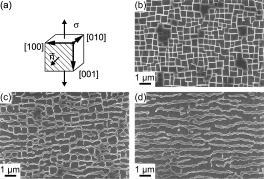
Single crystal Ni-based superalloys are typically used as turbine blades of advanced aircraft engines which operate at high temperatures. When the turbine spins at a constant speed, the centrifugal force exerts a constant stress which is far below the macroscopic yield stress to blades, leading to high temperature and low stress deformation (i.e. creep) of single crystal Ni-based superalloys. Understanding creep mechanisms and predicting creep properties have been a long standing demand for developing high-tech turbines. To achieve goal, macroscopic methods (e.g. macroscopic constitutive modelling) are insufficient at all, as in this case the plastic deformation takes place at external stress far below macroscopic yield stress. The microstructures must be informed. The typical microstructure evolution of single crystal Ni-based superalloys under high temperature and low stress creep is shown in Fig. 1 (Jacome et al., 2013). As can be seen, it mainly consists of cuboid phase and channel-like phase surrounding the phase. The crystalline orientations of the and phases are the same, this is why they are called ”single crystal” despite that there are two phases. Typically orientation is aligned with the centrifugal stress of blades. During creep, precipitates coarsen (or raft) to the direction normal to external loading, as shown in Fig. 1 (c) and (d).
To quantitatively understand the microstructure evolution and its effect on creep properties of single crystal superalloys, modelling and simulation works have been conducted using multi-scale methods such as microstructure informed constitutive modelling (Guo et al., 2021; Le Graverend, 2019; Rodas and Neu, 2018; Barba et al., 2018), discrete dislocation dynamics (Gao et al., 2015a, 2017, b), molecular dynamics (Yin et al., 2021; Wu et al., 2021a, b) and so on. The microstructure informed constitutive models (Guo et al., 2021; Le Graverend, 2019; Rodas and Neu, 2018; Barba et al., 2018) are typically implemented by finite element method with the element is larger than the characteristic length of , indicating that and phases are not explicitly resolved. The main benefit of doing so is that the simulation domain can be as big as the experimental sample and the creep properties can be predicted accurately if the model parameters are well fitted. The main drawback is that the spatial evolution of phases and their interactions with dislocations cannot be investigated. In contrast, dislocation dynamics and molecular dynamics can provide solid information on dislocations and the effect of on dislocations. However, the evolution of cannot be simulated because of the small time scale of discrete dislocation dynamics and molecular dynamics, which restricts the investigation of effect of dislocations on and the prediction of creep properties that are comparable to experiments. Phase-field method (PFM) offers a convenient framework to simulate the evolution of microstructures and predict creep properties as natural outcome of microstructure evolution (if coupling plasticity). Gaubert et al. (2010); Tsukada et al. (2011); Cottura et al. (2012) contributed the first attempts of coupling phenomenological or viscoelasticity to phase-field models to study the influence of plastic activities on the phase microstructures. Following the similar spirit, Wang et al. (2021, 2019); Yang et al. (2018); Tsukada et al. (2017) extended the simulations from 2D to 3D. Despite that the simulated evolution agrees with experimental observations well, the fundamental carries of plasticity—dislocations—are missing in the models. Experimental observations (Jacome et al., 2013, 2014; Wu et al., 2020b, 2016) show that dislocations play a crucial role during the creep of single crystal superalloys. The incorporation of dislocations into phase-field model can be traced back to the work of Rodney and Finel (2000); Wang et al. (2001); Rodney et al. (2003) who developed a phase-field description for discrete dislocations. That is a model at continuum scale with dislocation line still resolved, meaning that the computational cost is high and increases dramatically with the number of dislocation lines. The present authors Wu and Sandfeld (2016); Wu et al. (2017) contributed the first attempts on coupling phase-field and dislocation density based plastic model. Wu and Sandfeld (2017); Wu and Zaiser (2019); Wu et al. (2019) proved that the coupled models are applicable for investigating the effect of initial characteristics and external loading on the evolution of phases and dislocations during creep and fatigue of single crystal superalloys. As the continuum dislocation dynamics (CDD) in those work is double checked by systematic average of discrete dislocation dynamics and functional variation of dislocation energy by Groma et al. (2003, 2015), and numerically insured by Wu et al. (2018); Wu and Zaiser (2021), the physics of continuum dislocation dynamics is very solid. However, that PFM and CDD coupled model has two drawbacks. One is that the it currently does not have dislocation mechanisms other than dislocation glide, indicating that it can only simulate the primary creep but not the whole creep stage. Another is the ”swallow-gap” problem (will be explained in detail in the following section) that most dislocation density and PFM coupled models suffer.
Having the above mentioned in mind, we propose a model coupling PFM, dislocation density based plasticity and damage in present wok. The model is supposed to solve the ”swallow-gap” problem and simulate the whole creep stage with both microscopic and macroscopic features agree with experiments. The manuscript is organized as follows. The PFM, dislocation density based constitutive model and parameter determination will be introduced in Section 2. The stress benchmark, phase microstructure, dislocation, damage and creep property evolutions will be presented and discussed in Section 3. In the end, some conclusions are reached for the present work in Section 4.
2 Modelling and parameter determination
2.1 Phase-field model
We use the KKS phase-field model proposed by Kim et al. (1999); Zhou et al. (2010) to describe the phase evolution of single crystal Ni-based superalloys. As we focus on the effect of mechanics associated mechanisms instead of chemistry associated mechanisms, a binary Ni-Al system would be proper for this purpose. The phase system is described by the composition field of Al (i.e. ) and order parameter field , where as there are four different variant of the phase. In the phase and , while in the phase and , where and are the equilibrium composition of phase and phase, respectively. The interface is regarded as a mix of two phases. In this way, we are informed with the phase microstructure by the and fields. The basic idea of phase-field is to construct the total free energy first, then the system evolves according to minimization of total free energy. The total free energy is formulated as a functional by
| (1) |
where and are the chemical energy density and elastic energy density, respectively. The formula of is given by
| (2) |
where and are the bulk free energy density of phase and phase, respectively. and are two interpolation functions. The first three terms represent the bulk energy and the last term represent the gradient energy on the right hand side of Eq. (2). The formulas of and are given by
| (3) |
| (4) |
The following features can be deduced: 1) and ; 2) and and ; 3) and and ; 4) and and . The four features in turn represent the cases in the phase, phase, interphase and antiphase boundary (APB), respectively. APB is the boundary between th and th () variants of the phase. Note that the main difference between the third and fourth case is that the term with in Eq. (4) is zero for the former while non-zero for the later, meaning that the term with especially counts the addition energy caused by the APB. and in Eq. (2) are the bulk free energy density of phase and phase, respectively, given by
| (5) |
| (6) |
where serve as energy density scale of the bulk free energy. It actually should be different for the and phases (i.e. and ). However, since the difference between and is within 10%, we use for simplicity. By far, we have constructed the chemical energy density of the system, another important energy is the elastic energy density, given by
| (7) |
where elastic strain and stress follow the Hooke’s law
| (8) |
where is the stiffness tensor which is regarded as a interpolation of the stiffness tensors of the and phases. In the small deformation region, the total strain can be regarded as the superposition of elastic and inelastic strains, namely
| (9) |
The inelastic strain consists of the misfit strain and plastic strain, given by
| (10) |
| (11) |
| (12) |
where I is the identity tensor, is the plastic shear and is the projection tensor of slip system which will be introduced soon in the next subsection. Substituting Eq. (8)-(12) into the mechanical equilibrium equation and solve it by the spectral method of micromechanics, the elastic strain, stress and energy can obtained. The evolution of Eq. (1) follows the renowned Cahn-Hilliard and Allen-Cahn equations proposed by Cahn and Hilliard (1958); Allen and Cahn (1979)
| (13) |
| (14) |
where and are the mobility coefficients of diffusion and local order-disorder processes, respectively, which we assume to be isotropic and homogeneous.
2.2 Kinematics of dislocation density based constitutive model
Kinematics describes how dislocations and plastic shear evolve at a given velocity. The evolution rate of dislocation density can generally be described by,
| (15) |
where is the total dislocation density and is the plastic shear of slip system . There are two different ideas to develop dislocation-based constitutive modes in the framework of continuum mechanics. One is to directly derive from energy functional derivative of dislocation system or systematic coarse-graining of discrete dislocation dynamics (Groma et al., 2003, 2015; Hochrainer et al., 2007). Another is to first develop the formulations of and , then the formulation of is fixed consequentially. The former leads to the so called ”continuum dislocation dynamics” describing physical dislocation density motion, which is robust from physics point of view but expensive from numerics point of view. The later leads to dislocation density evolution which is more phenomenological but computationally faster. Taking the later idea and following the spirit of Mecking and Kocks (1981); Kubin and Estrin (1990), together with the consideration of experimental observations of single crystal Ni-based superalloys, we propose the formulas of as
| (16) |
| (17) |
where is the density of mobile dislocations, is the density of immobile dislocations, is the magnitude of Burgers vector and is the average width of channels. , , and are four nondimentional parameters with positive values. The sum of and gives the total dislocation density of slip system by . gives the total dislocations density of the whole domain and gives the averaged or macroscopic total dislocations density of the whole domain, where is the volume of numeric grid and is the volume of the whole domain. is the dislocation velocity. is the Burgers vector. is a indicator which equals one if and zero otherwise. Obviously, Eq. (16) and Eq. (17) contain the Orowan equation which links the plastic shear, mobile dislocation density and velocity by
| (18) |
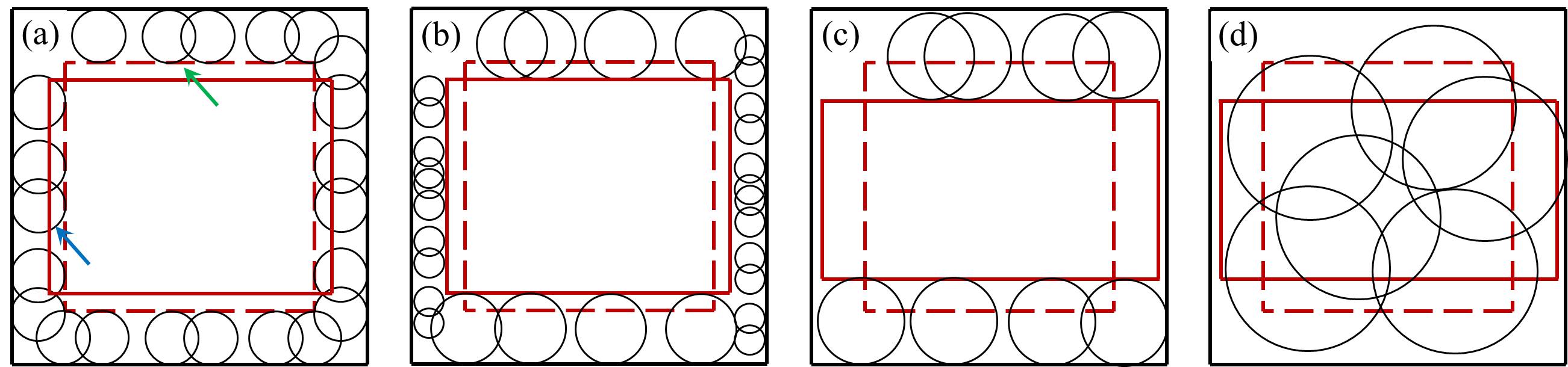
Let us first understand the physics behind Eq. (16) and Eq. (17). The first term on the right hand side of Eq. (16), , represents the reduction of mobile dislocation density due to mechanisms such as trapping or capturing of mobile dislocations by immobile dislocations. These mobile dislocations become immobile dislocations and hence a corresponding production term of immobile dislocations, , appears on the right hand side of Eq. (17). The second term on the right hand side of Eq. (16) and Eq. (17) stands for the transition of mobile dislocations to immobile dislocations due to the block of interfaces. Note that according to the formulation of the second term, the narrower the channel, the sooner the mobile-to-immobile transition take place, which also agrees with experimental observations. The third term on the right hand side of Eq. (16) solve the ”swallow-gap” problem surrounding the rafted precipitate during simulation, as illustrated in Fig. 2 (a) and (b). When the precipitate rafts from the dashed red line morphology to the solid red line morphology, dislocations should move with interfaces according to experiments (see Fig. 2 (b)), not stay stationary and be swallowed by the vertical interfaces (see the blue arrow in Fig. 2 (a)) and leaving a dislocation-free gap near the horizontal interfaces (see the green arrow in Fig. 2 (a)). However, the ”swallow-gap” phenomenon illustrated by Fig. 2 (a), especially the swallowing of dislocations at vertical interfaces which is not allowed by anti-phase boundary energy before tertiary creep stage, has became a common problem in the dislocation density based phase-field simulation of superalloys Wu et al. (2020a, 2017); Wu and Zaiser (2019). The third term on the right hand side of Eq. (16) solves this ”swallow-gap” problem in the following way: 1) in the phase (see (22)) is zero and is one, the third term brings multiplication of dislocations at the horizontal gap, but the third term decreases as the mobile dislocation density increases because of and eventually balances the first two terms; 2) in the phase is not zero, is zero if and transfers mobile dislocations swallowed at the horizontal interfaces to immobile dislocations by the first two terms on the right side of Eq. (16), then the third term on the right side of (17) further reduces the swallowed dislocations. According to experimental observation, the tertiary creep is accomplished by dislocations cutting in the , as illustrated in Fig. 2 (c) and (d). This is also ensured by the third term on the right hand side of Eq. (16): is one if and the big leads to the multiplication of dislocations inside the phase.
2.3 Dynamics of dislocation density based constitutive model
Dynamics describes how different stresses affect the velocity of dislocation evolution. The dynamic equations should recover some key features observed in experiments. In the present work we propose the stress formula as
| (19) |
where is the diving stress, is the friction stress, is the line tension stress. The velocity is proposed as
| (20) |
where the and are introduced for dimensional purpose. In the following, the origin of different stress terms in Eq. (19) will be explained in detail. The formula of is given by
| (21) |
where is the resolved shear stress and is the APB stress. (21) has the feature that in the phase and in the phase . comes from the fact that an th variant converts to th () variant of the phase when dislocations in the phase shear into the phase, and the sheared plane is actually an boundary between the th and th () variants (i.e. APB) with much bigger energy than the interface, which serves a resistance stress preventing dislocations in the phase to cut into the phase. Before is big enough to let dislocations cut through phase, dislocations swallowed by the vertical interface during rafting are driven out by the . This is why is regard as a part of the driving stress for dislocations inside the phase in Eq. (21), as has been explained in detail with the assistance of Fig. 2. The formula of is given by
| (22) |
where is the APB energy and ensures that the APB stress exists in the phase only. The formula of is given by
| (23) |
where represents the increment of resolved stress due to the reduction of contact area by voids and cracks. initially equals before deformation and increases as the deformation goes on, reaching eventually at rapture. is the main reason that the APB resistance Eq. (22) cannot be overcame at the early creep stage but can be overcame at the late creep stage. Since the local elastic energy is often used as criteria for crack and void formation, the evolution of is set to be
| (24) |
where is a coefficient controlling the kinetic of damage evolution. The formula of is proposed as
| (25) |
where is the shear modulus. comes from that fact that curved dislocations need to overcome the maximum line tension stress to multiply in the channels. Since in the phase and in the phase, serves as a spatial indicator which indicates that the maximum line tension stress is considered only in the phase. Because when dislocations cut into the phase, the dislocation line curvature increases dramatically, meaning that the line tension stress decreases to negligible value. comes from the fact as more and more dislocations are blocked and pile up at the interface, the bowing out space decreases and resistance of dislocation bowing out increases. It is worth mentioning that Cottura et al. (2016); Wu et al. (2017) proposed back stress terms in phase-field and dislocation-based plasticity coupled models for single crystal Ni-based superalloys. Forest and Sedláček (2003) has shown that the back stress in continuum models of straight dislocations actually mimics the hardening by line tension stress of curved dislocations in the case that dislocation motion is confined in narrow channels. Hence, the physics behind the line tension stress in the present and the back stress proposed by Cottura et al. (2016); Wu et al. (2017) is the same. The formula of is given by
| (26) |
where is a value typically in the range of . The Taylor friction stress represents the mutual trapping of positive and negative dislocations into dipolar or multipolar configurations.
2.4 Parameter identification and simulation setup
We do creep loading simulations at , so all the parameters have their values at . The equilibrium composition of the and can be obtain from phase diagram. Other parameters in Eq. (2)-(6) are mutually restricted and determined by 1D numeric experiments with rules (Zhou, 2008; Cottura et al., 2016): 1) there are more than 5 grids in the interface to avoid numeric pinning; 2) the interface energy is in the range of with the bulk energy and gradient energy contribute equally; 3) the APB energy is more than two times of the interface energy. The stiffness tensor and misfit of the interface in Eq. (8)-(11) can be found in experimental or lower scale calculation literatures. The main slip systems are for FCC crystals, as four of them have zero resolved shear stress under loading, we only take the eight active slip systems whose projection tensors are listed in Table 1. The mobility coefficient in Ep. (13) is determined such that the Ni-Al inter-diffusion is recovered, because Ep. (13) eventually abides by the Fick’s laws of diffusion. The mobility coefficient in Ep. (14) takes a much larger value than by , where is the grid spacing. Because from physics point of view, local order-disorder is much fast than diffusion. The parameters associated with dislocation density based constitutive modes in Eq. (16)-(26) are mutually constrained. The difference between any of the two terms (i.e. the terms with ) on the right hand side of and cannot always exceed two orders of magnitude, otherwise the term which is constantly two orders of magnitude smaller than the rest can be abandoned from the formulas. The , and in the dislocation velocity formula, which have influence on the shape of and hence , can be adjusted with the experimental data of . The has influence on the shape of which is typically around initially and increases to after primary creep according to experiments.
Having the above mentioned strategies in mind, the parameters are determined as follows: , , , , , , , , , , , , , , , , , , , , , , , , . The governing equations are solved by the spectral method (Hu and Chen, 2001).
| and | ||
|---|---|---|
| 1 | , | |
| 2 | , | |
| 3 | , | |
| 4 | , | |
| 5 | , | |
| 6 | , | |
| 7 | , | |
| 8 | , |
3 Results ans discussions
3.1 Stress benchmark
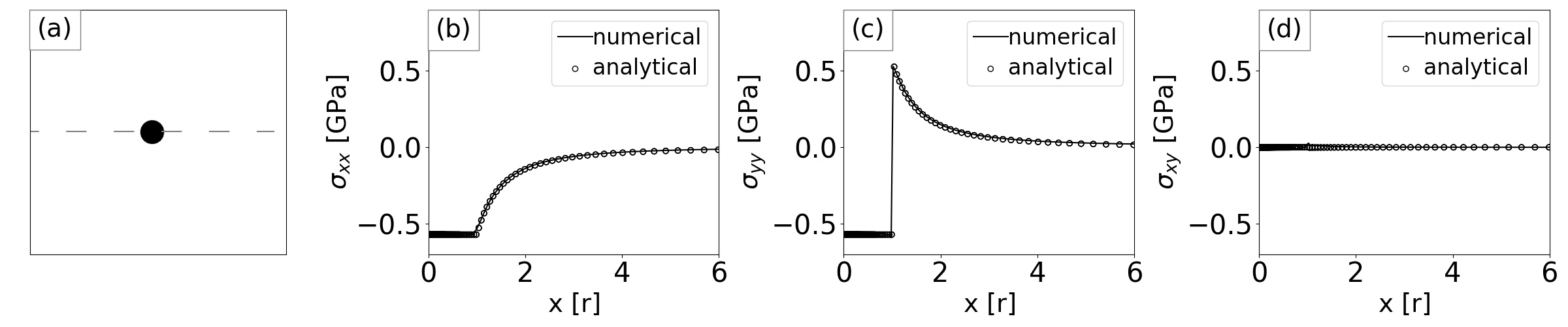
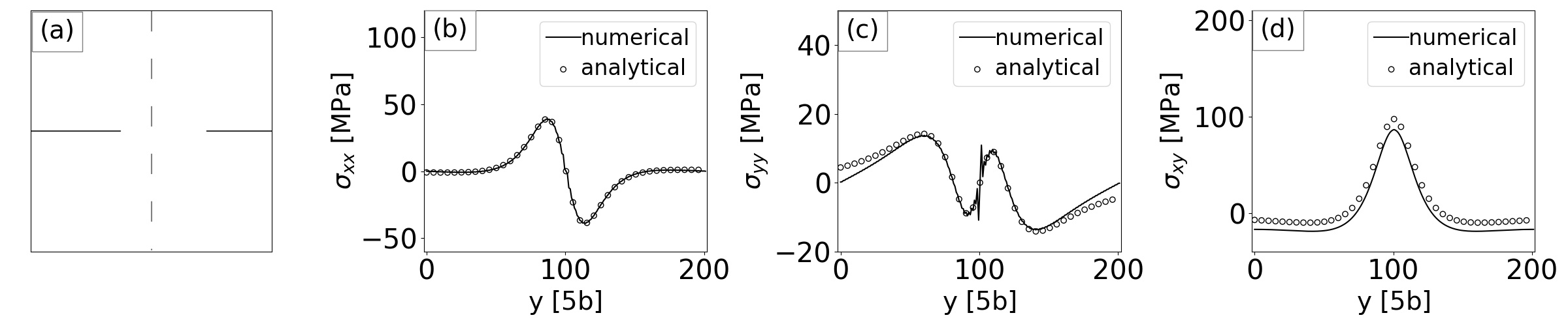
As stress and strain are crucial issues for the present work, we fist validate the numerical stresses by analytical solutions, as shown in Fig. 3 and Fig. 4. Both cases are set to be isotropic and homogenous, because the analytical solutions of them have been widely accepted (Gururajan and Abinandanan, 2007; Meng et al., 2012; Anderson et al., 2017). Fig. 3 presents the case that a small circular inclusion is located at the center of the domain (see Fig. 3(a)). The diagonal components of the misfit strain between inclusion and matrix are set be and the off-diagonal components are set to be zero, such that the inclusion has similar misfit strain feature with the . The elastic constants are set to be , and to make material isotropic. The three stress components are plotted along (i.e. the dashed line) of the domain (see Fig. 3(b)-(d)), where is the vertical length of the domain. Fig. 4 presents the case that plastic shear of one Burger vector is located at the horizontal center of the domain. One can understand the situation by imaging a positive dislocation glides from the left boundary and parks at the edge of plastic shear, while a negative dislocation glides from the right boundary and parks at the edge of plastic shear, therefore generating plastic shear as illustrated in Fig. 4(a). In this case the diagonal components of the inelastic strain are zero and the off-diagonal components are , where is the grid spacing which we set to be . The three stress components are plotted along (i.e. dashed line) of the domain (see Fig. 4(b)-(d)), where is the horizontal length of the domain. As can be seen, the numerical stresses in both cases agree with analytical solutions very well.
3.2 Phase microstructure evolution
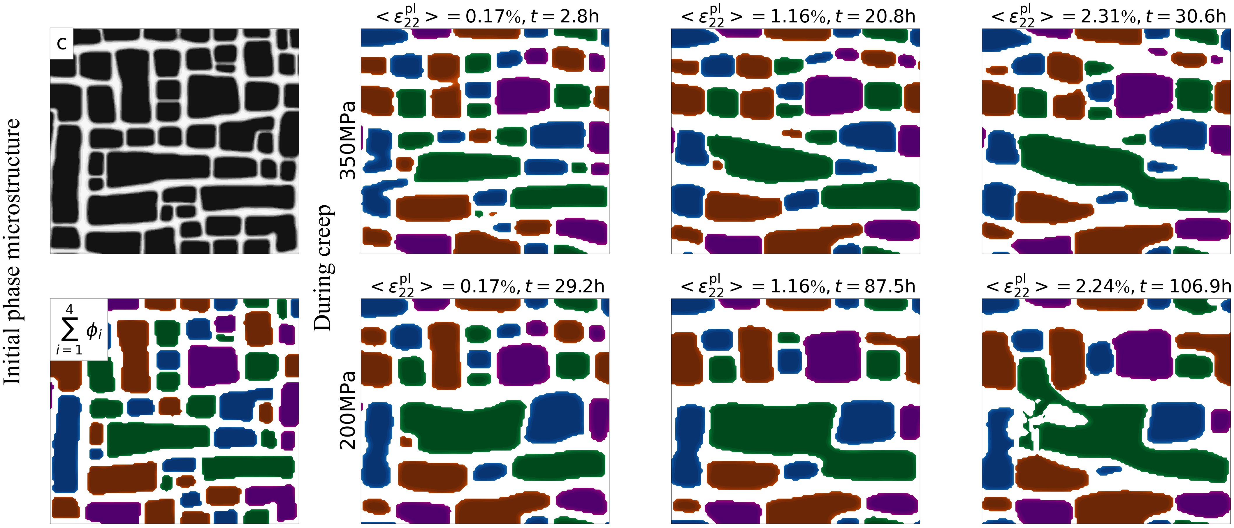
The phase microstructures before and during creep are shown in Fig. 5. The four variants are distinguished by four different colors. The initial phase microstructure for creep is generated by setting composition field around with small fluctuation which leads to spinodal decomposition type of precipitating of the phase from supersaturation phase, according to the chemical free energy of phase microstructure. As the precipitation goes on, the well-formed phase microstructure is obtained as the initial microstructure for creep. The simulated well-formed phase microstructure agrees with the experimental phase microstructure. Specifically, the representative shapes of the precipitates including square, rectangle and L-shape observed in experiments (Fleischmann et al., 2015; Gao et al., 2015b) also present in the simulated phase microstructure. and tensile creep loadings are applied along the vertical direction (i.e. ). Under loading, it is obvious that the precipitates raft to the horizontal direction. A notable feature during early creep (i.e. ) is that the vertically elongated precipitates are splitting. As the creep goes on and reaches the transition between secondary and tertiary creep (), the horizontal interfaces become increasingly wavy, but the precipitates at different layers are not connected yet. However, during the tertiary creep (), it is notable that precipitates at different layers try to connect each other, forming a microstructure that the channels are surrounded by precipitates. Such a phenomenon is the renowned topological inversion during tertiary creep of single crystal superalloys, because initially the phase microstructure is that the precipitates surrounded by channels but now it is the other way round. Under loading, the principal features of phase microstructure evolution are similar with those under loading. The main differences are: 1) it take much longer time to reach the same macroscopic plastic strain in the case of loading; 2) the rafting of precipitates is less severe in the case of loading, due to the lower mechanical energy. The phase microstructure evolution in Fig. 5 agree with massive experimental observations of single crystal superalloys under similar loading conditions (Viguier et al., 2011; Shui et al., 2006; Fedelich et al., 2012; Miura et al., 2000a). The mechanical energy induced phase microstructure evolution can be explained based on the dislocation and damage evolutions as follows.
3.3 Dislocation and damage evolutions
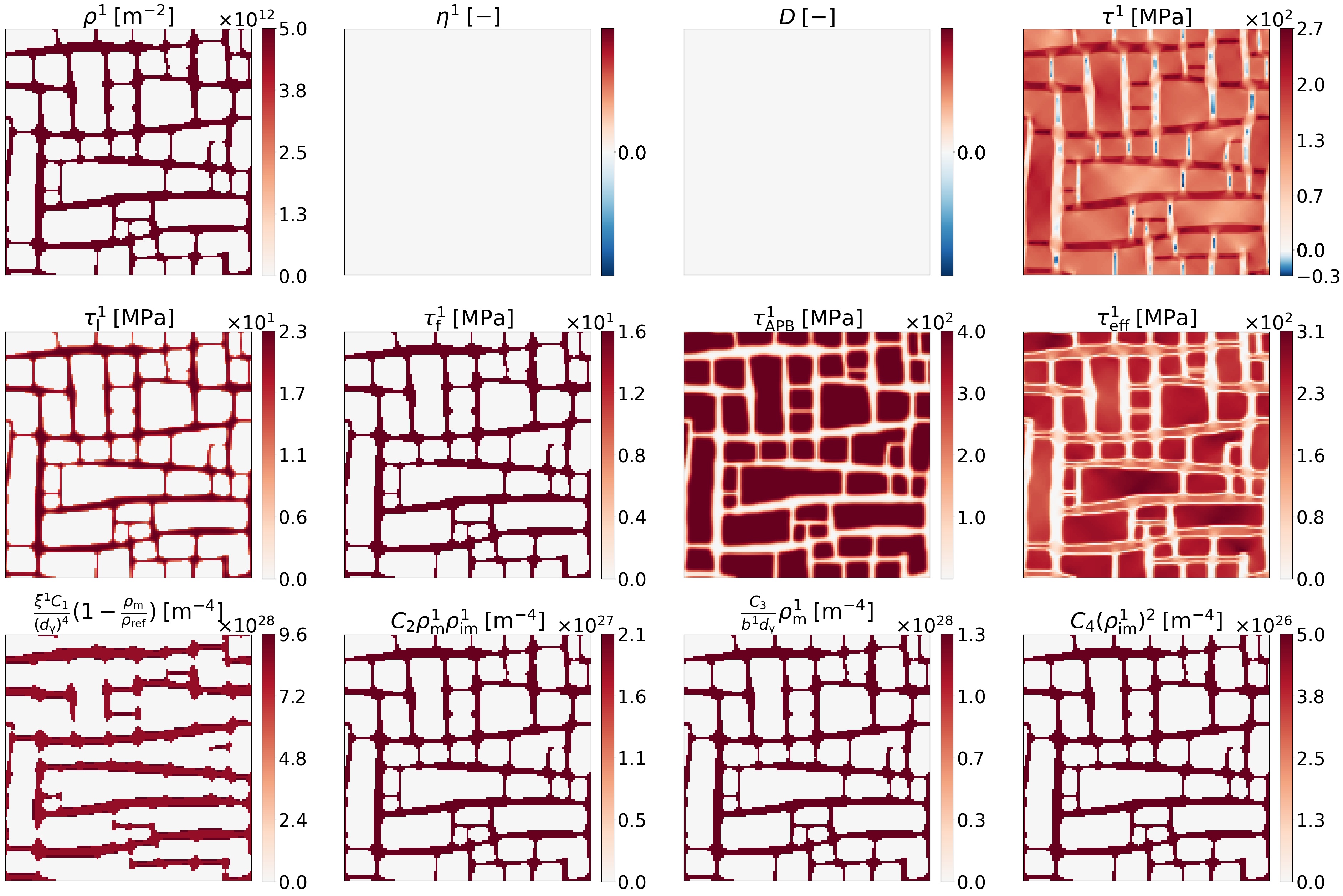
The initial dislocation of slip system one and damage associated fields are shown in Fig. 6. We always use red color and blue color for positive and negative values, respectively, and the white color represents zero. The maximum and minimum values of each color bar are the real maximum and minimum values of the corresponding field. The initial dislocation density of slip system one at the channels is about , leading to average dislocation density about which agrees with the typical experimental observation (Jacome et al., 2013; Miura et al., 2000b). The damage and plastic shear vanish everywhere, as initially there is no damage and plastic activity. The resolved shear stress ranges from about in the vertical channels to in the horizontal channels. Note that such a distribution of resolved shear stress contains the contribution of coherent misfit and external loading. The line tension stress only exists in the channels, as the line tension stress mimics the line tension when dislocations are confined in the channels. The fraction stress only exists in the channels as well and has a uniform value around , because we prescribe uniform initial dislocation density in the channels. In contrast, the APB stress , which inhibits dislocations from cutting into the precipitates, possesses the precipitates and has a value of . Experimental observation shows that dislocation motion mainly takes places in the horizontal channels (Link et al., 2000). This can be expected and explained by the distribution of effective stress which has values over in the horizontal channels while vanishes in the vertical channels. Besides, experiments show two features during the early creep stage: 1) most dislocations are mobile and multiply in the channels, 2) mobile dislocations are blocked by interfaces and turned into immobile. The former feature is captured in the simulation that initially the multiplication term dominates over the rest terms of mobile dislocations. The latter feature is captured in the simulation that initially the transfer of mobile dislocations to immobile dislocations due to interfaces (i.e. ) dominates over that due to mobile-immobile interactions (i.e. ). Note that for the latter feature, experiments show that some of the mobile dislocations may bypass around the precipitates and leave a loop surrounding the precipitates, but the back resistance due to resident loops increases as the resident loops reside more and more, making the dislocation multiplication and bypass increasingly difficult. This process, the resistance in the channels increases as the dislocation density increases, is actually captured by the line tension stress term with a prefactor .
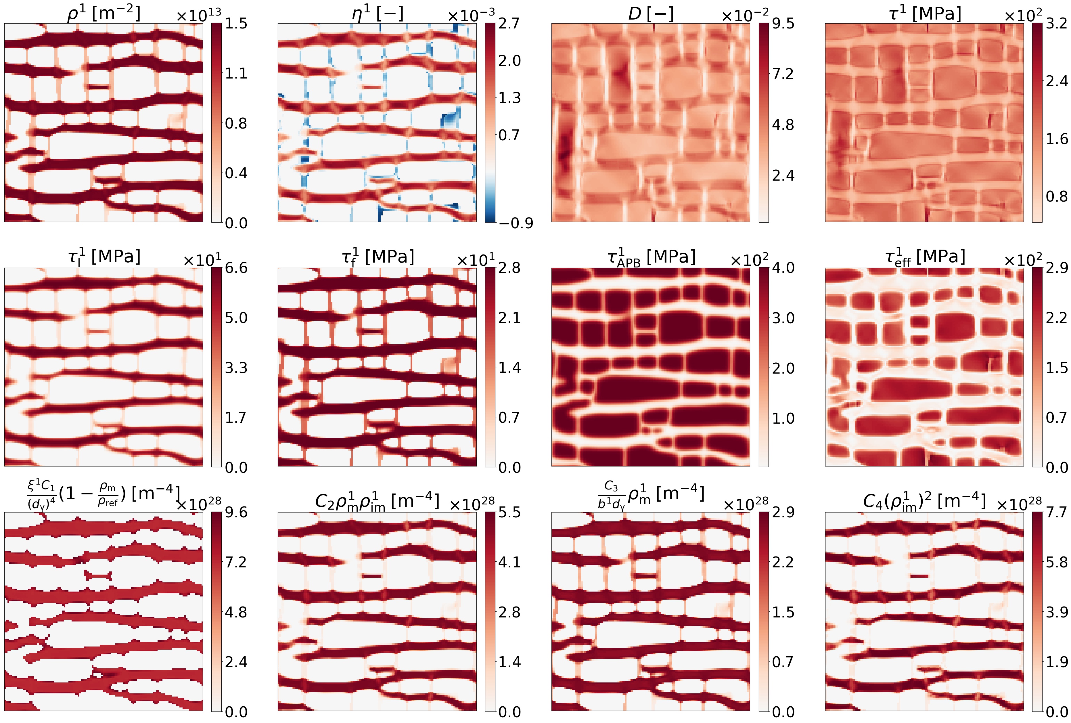
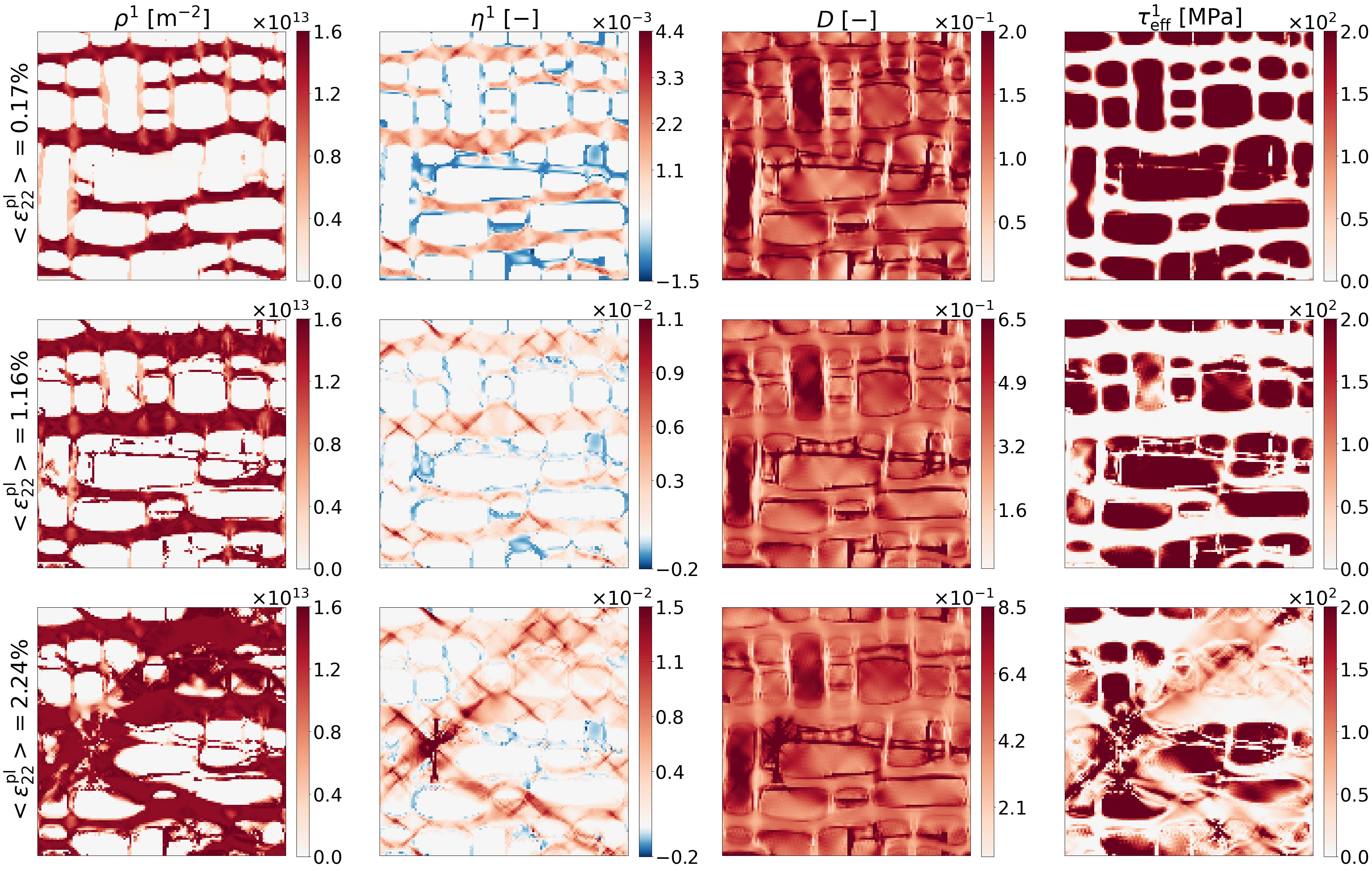
After creep of , dislocation of slip system one and damage associated fields are shown in Fig. 7. It is at early creep stage and the corresponding macroscopic plastic strain along loading direction is . The dislocation density in the horizontal channels increases to , while that in the vertical channels remains the same. Massive plastic shear can be observed in the horizontal channels. Thanks to the treatment explained Fig. 2, the ”swallow-gap” problem is solved and the dislocation density distribution now agree with experimental observation well. This can be evidently seen in the vertical channels where negative plastic shear (i.e. ) is obtained. According to the initial effective stress in Fig. 6, there should be no plastic activity in the vertical channels. However, as the precipitates raft to the horizontal direction, some dislocations initially in the vertical channels are swallowed by the vertical interfaces. Then, the APB stress pushes the swallowed dislocation out of the precipitates, leaving negative plastic shear near the vertical interfaces. Such a strong inhomogeneous distribution of plastic activity dramatically alter the elastic energy distribution, which bring a significant to the rafting of phase microstructures. This can be evidently seen from the damage (i.e. ) field. According to the formula of damage, it has strong correlation with the elastic energy distribution. As a consequence of the inhomogeneous dislocation motion, the elastic energy in the horizontal channels prevails over that in the vertical channels. The microstructures tend to widen the horizontal channels to release the intensive elastic energy and hence cause rafting of precipitates in the horizontal direction. The stress terms (i.e. , , , and ) are obviously changed in comparison with their initial fields, due to the evolution of phases and dislocations. A notable feature is that the effective stress in the horizontal channels is reduced compare with the initial state, because dislocation multiplication increases the line tension stress and friction stress. The transfer of mobile to immobile dislocations is also enhanced as the dislocation density increases. Now the transfer terms (i.e. and ) of mobile to immobile dislocations increases to the same order of magnitude as the multiplication term (i.e. ), but still smaller than the multiplication term, indicating that dislocation multiplication still goes on with a decreasing multiplication rate. The annihilation of forest immobile dislocations (i.e. ) is also enhanced as a result of increment of immobile dislocation density.
After creep of , dislocation of slip system one and damage associated fields are shown in Fig. 8. It is at the transition between secondary and tertiary creep stages (or the transition between linear and exponential creep) according to the creep curve (see Fig. 13). The corresponding macroscopic plastic strain along loading direction is . A notable feature is that a few dislocations start cutting into the precipitates. The reason is that now the damage has the maximum value around inside precipitates, leading to the maximum resolved shear stress around which is big enough to overcome the APB stress. The summations of the terms with and almost reach balance in the channels. This is why the increase rates of dislocation density and plastic shear are low and reach a minimum during the secondary creep.

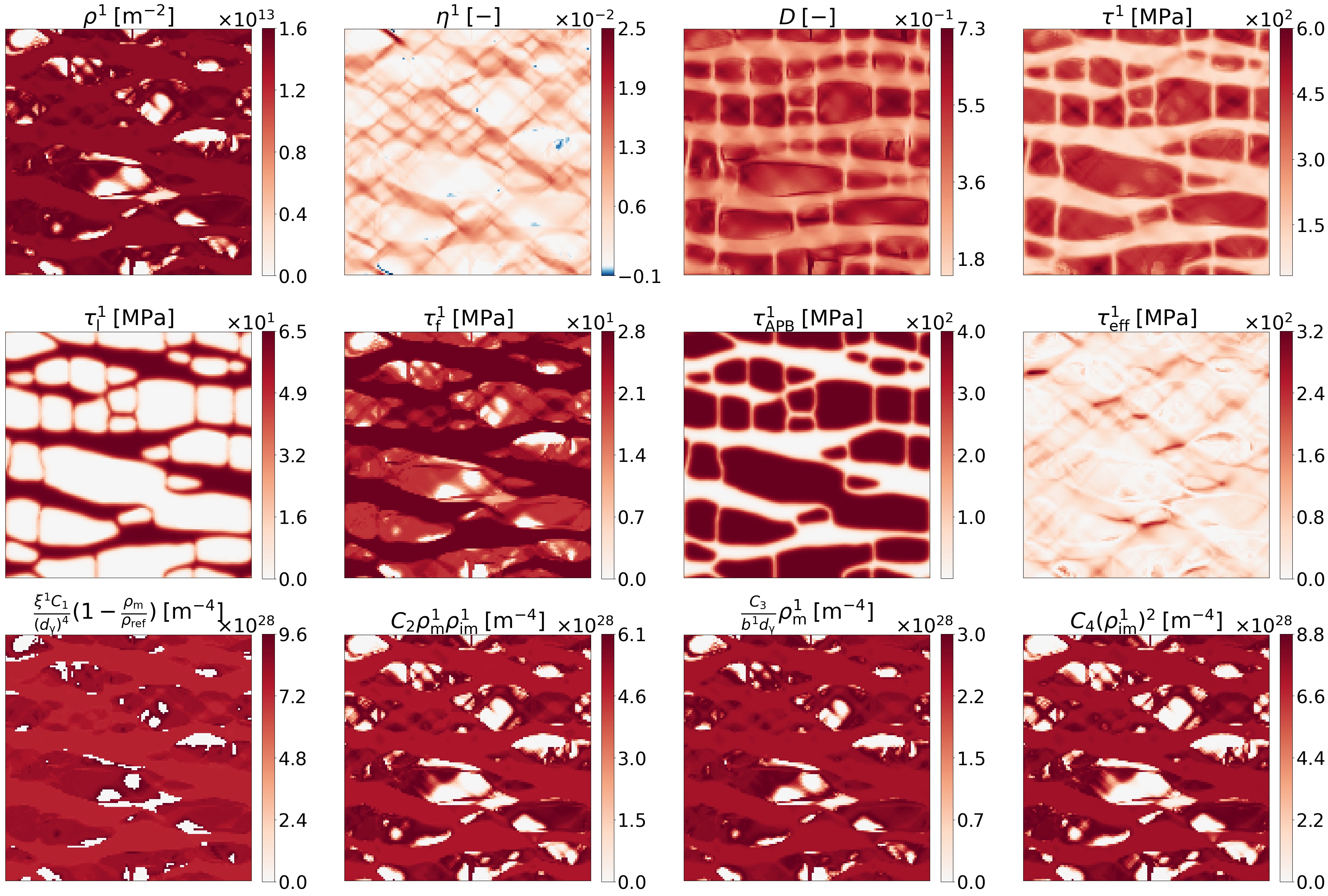
After the creep of , dislocation of slip system one and damage associated fields are shown in Fig. 9. It is obviously at the tertiary creep stage. The corresponding macroscopic plastic strain along loading direction is . Now the resolved shear stress is big enough to over come the APB stress inside most of the precipitates. Because of that, massive dislocations cut into the precipitates can be observed from the dislocation density field. Another interesting feature along with the massive dislocation motion is the formation of slip bands of or (see the field). Such slip bands are typically observed in tensile loading of FCC single crystals when the resolved shear stress is big enough to let dislocation moves in the whole sample area (Westbrooke et al., 2005). As for the topological inversion, it is not observed at the transition between secondary and tertiary creep stages but obvious during the tertiary creep stage, it seems to suggest the dislocation shearing precipitates is the key factor triggering the topological inversion. When dislocations cut into the precipitates, the elastic energy distribution is changed and such a change affects the evolution the . Anyway, at this point the material has suffered severe degradation and is not qualified for service any more.
The dislocation of slip system one and damage associated fields under loading are shown in Fig. 10. To compare with those under , we plot the fields at the similar macroscopic plastic strain (i.e. and ). As can be seen, the evolutions of dislocation in slip system one and damage associated fields under loading are similar with those under loading. It means that as long as it is at the high temperature and low stress loading regime, the microstructural mechanisms are the same under different external stresses. The microstructural images are always similar at the similar macroscopic plastic strain, despite the time reaching the macroscopic plastic strain dramatically increases as the external stress decreases. It can be reasonably deduced from the present results that at high stress loading regime (the external loading is bigger than about ), the microstructural mechanisms are different from those at low stress loading regimes. Because dislocations can cut into the precipitates and the beginning of deformation. Such a distinction of low stress regime and high stress regime also agree with experiments (MIURA et al., 2003; Rae and Reed, 2007; Matan et al., 1999).
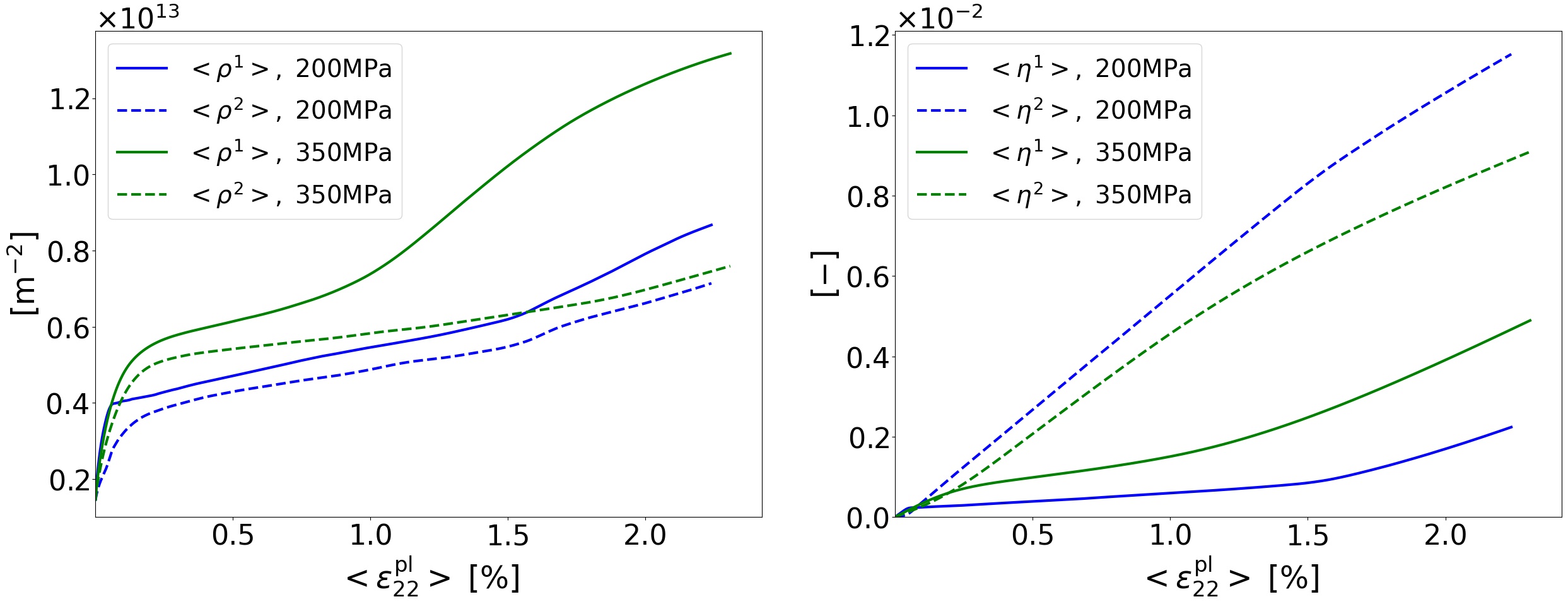
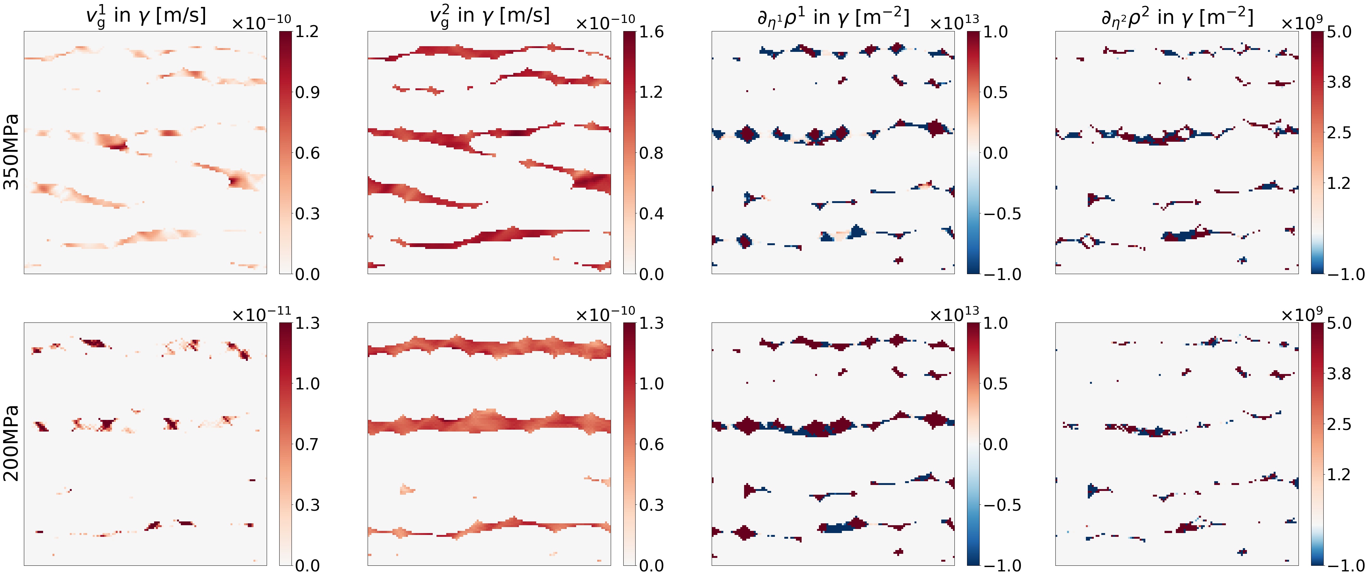
The dislocation evolutions of odd slip systems are quantitatively very similar with each other, so do those of the even slip systems. The evolution mechanisms of odd and even slip systems are qualitatively the same, but have some distinctions quantitatively, as shown in Fig. 11. The macroscopic value of a quantity can be obtained by doing spatial average of that quantity by . It is not a surprise that there are more dislocations under than under . However, it is interesting that there are less dislocations but more plastic shear in the even slip systems than in the odd slip slip systems, regardless of the external stress. This can be explained from the fields plotted in Fig. 12. The rafted phase microstructures result in bigger resolved shear stress in the slip system two than in the slip slip one, which consequentially leads to bigger dislocation evolution velocity and plastic shear (see (18)) in the slip system two. At first glance, it seems that bigger dislocation evolution velocity leads to bigger dislocation density in the slip system two as well according to (16) and (17). Nevertheless, the evolution of dislocation density also depends on the . It can be seen that is much bigger than regardless of the external stress ( and for , and for ), leading to bigger dislocation density in the slip system one than in the even slip system two.
3.4 Macroscopic properties
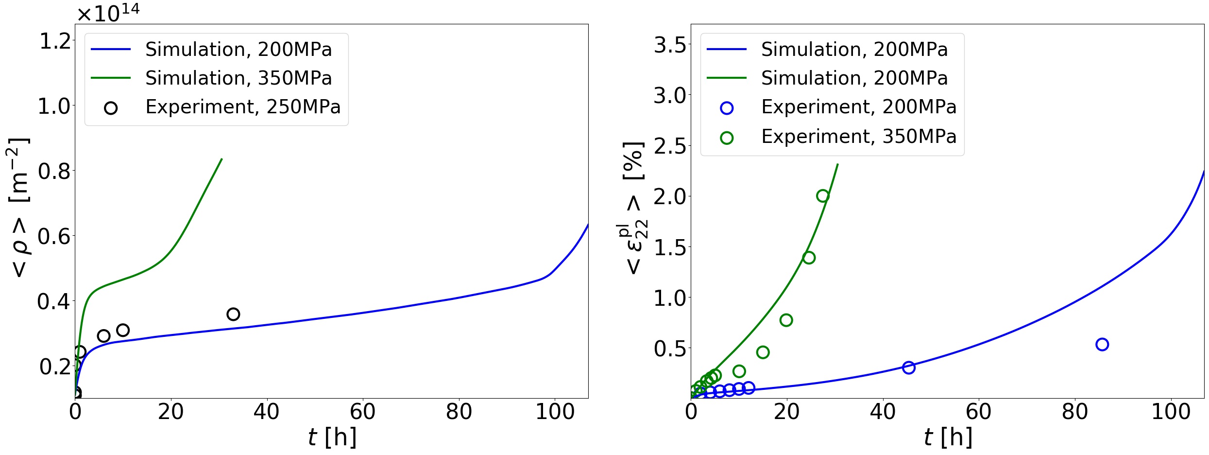
The simulated temporal evolutions of macroscopic creep properties are shown in Fig. 13 and compared with experimental data. As can be seen, the simulated shape and value of the curves principally agree with the experimental results (Kondo et al., 2014; Link et al., 2000). The increments of dislocations and creep strain during early creep stage are due to the multiplication of dislocation in the channels. The increments of dislocations and creep strain during tertiary creep stage are due to the dislocation cutting into precipitates. The minimum creep rates under and are and , respectively, which are very close to experimental data under similar loading conditions (Miura et al., 2000b).
Although we present the creep simulation of single crystal superalloys here, the coupled framework can be applied to polycrystals with some modifications. Firstly, a set of additional order parameters, for instance where indicates different grains, should be added to the phase-field model. Then, the might be replaced by the grain size to recover the Hall-Petch hardening due to grain boundaries. The APB stress might be replaced by the stress needed to nucleate dislocations from grain boundary. Since we use a relatively simple description for the damage, it can be improved by a more physical way (see (Ambati et al., 2015) for example). We may improve the current model and extend its application following these ideas in the future.
4 Conclusions
A phase-field, dislocation density based plasticity and damage coupled model is developed and applied to the high temperature creep of single crystal superalloys under and . The following conclusions can be drawn from the present work:
-
1.
The simulated spatial-temporal evolutions of phase microstructures during the whole creep stage agree with experiments well. Some key features like rafting and topological inversion of phase microstructures can be captured. The strong inhomogeneous plastic activity (a lot in the horizontal but a little in the vertical channels) is the main reason causing rafting, apart from the inhomogeneous elasticity. The dislocation cutting into precipitates is likely to be the main reason triggering topological inversion of phase microstructures.
-
2.
The simulated spatial-temporal evolutions of dislocations during the whole creep stage principally agree with experiments. Some representative features like dislocation multiplication in the channels, mobile-immobile transition due to block of interfaces and cutting into precipitates are observed in the simulations. Especially, the ”swallow-gap” problem is solved in the present model. The even slip systems produce less dislocations but more plastic slip than the odd slip systems, if the slip systems are defined as the present work.
-
3.
The simulated macroscopic properties including the minimum creep rate, dislocation density and creep curves agree with experiments. The increments of dislocations and creep strain during early creep stage are due to the multiplication of dislocation in the channels. The increments of dislocations and creep strain during tertiary creep stage are due to the dislocation cutting into precipitates.
-
4.
Since the simulated microscopic and macroscopic evolutions all principally agree with experiments, it is fair to state that the kinematics and dynamics of present model are principally reasonable. The present model is applicable for understanding and predicting the creep microstructures and properties of single crystal superalloys.
Acknowledgment
The research is financially supported by National Natural Science Foundation of China (12002275) and Natural Science Foundation of Shaanxi Province (2020JQ-125).
References
- Allen and Cahn (1979) Allen, S.M., Cahn, J.W., 1979. A microscopic theory for antiphase boundary motion and its application to antiphase domain coarsening. Acta metallurgica 27, 1085–1095.
- Ambati et al. (2015) Ambati, M., Gerasimov, T., De Lorenzis, L., 2015. A review on phase-field models of brittle fracture and a new fast hybrid formulation. Computational Mechanics 55, 383–405.
- Anderson et al. (2017) Anderson, P.M., Hirth, J.P., Lothe, J., 2017. Theory of dislocations. Cambridge University Press.
- Barba et al. (2018) Barba, D., Alabort, E., Garcia-Gonzalez, D., Moverare, J., Reed, R., Jérusalem, A., 2018. A thermodynamically consistent constitutive model for diffusion-assisted plasticity in ni-based superalloys. International Journal of Plasticity 105, 74–98.
- Cahn and Hilliard (1958) Cahn, J.W., Hilliard, J.E., 1958. Free energy of a nonuniform system. i. interfacial free energy. The Journal of chemical physics 28, 258–267.
- Cottura et al. (2016) Cottura, M., Appolaire, B., Finel, A., Le Bouar, Y., 2016. Coupling the phase field method for diffusive transformations with dislocation density-based crystal plasticity: Application to ni-based superalloys. Journal of the Mechanics and Physics of Solids 94, 473–489.
- Cottura et al. (2012) Cottura, M., Le Bouar, Y., Finel, A., Appolaire, B., Ammar, K., Forest, S., 2012. A phase field model incorporating strain gradient viscoplasticity: application to rafting in ni-base superalloys. Journal of the Mechanics and Physics of Solids 60, 1243–1256.
- Fedelich et al. (2012) Fedelich, B., Epishin, A., Link, T., Klingelhöffer, H., Künecke, G., Portella, P.D., 2012. Rafting during high temperature deformation in a single crystal superalloy: experiments and modeling. Superalloys 2012 6, 491.
- Fleischmann et al. (2015) Fleischmann, E., Konrad, C., Preußner, J., Völkl, R., Affeldt, E., Glatzel, U., 2015. Influence of solid solution hardening on creep properties of single-crystal nickel-based superalloys. Metallurgical and Materials Transactions A 46, 1125–1130.
- Forest and Sedláček (2003) Forest, S., Sedláček, R., 2003. Plastic slip distribution in two-phase laminate microstructures: dislocation-based versus generalized-continuum approaches. Philosophical Magazine 83, 245–276.
- Gao et al. (2015a) Gao, S., Fivel, M., Ma, A., Hartmaier, A., 2015a. Influence of misfit stresses on dislocation glide in single crystal superalloys: A three-dimensional discrete dislocation dynamics study. Journal of the Mechanics and Physics of Solids 76, 276–290.
- Gao et al. (2017) Gao, S., Fivel, M., Ma, A., Hartmaier, A., 2017. 3d discrete dislocation dynamics study of creep behavior in ni-base single crystal superalloys by a combined dislocation climb and vacancy diffusion model. Journal of the Mechanics and Physics of Solids 102, 209–223.
- Gao et al. (2015b) Gao, S., Rajendran, M.K., Fivel, M., Ma, A., Shchyglo, O., Hartmaier, A., Steinbach, I., 2015b. Primary combination of phase-field and discrete dislocation dynamics methods for investigating athermal plastic deformation in various realistic ni-base single crystal superalloy microstructures. Modelling and Simulation in Materials Science and Engineering 23, 075003.
- Gaubert et al. (2010) Gaubert, A., Le Bouar, Y., Finel, A., 2010. Coupling phase field and viscoplasticity to study rafting in ni-based superalloys. Philosophical Magazine 90, 375–404.
- Groma et al. (2003) Groma, I., Csikor, F., Zaiser, M., 2003. Spatial correlations and higher-order gradient terms in a continuum description of dislocation dynamics. Acta Materialia 51, 1271–1281.
- Groma et al. (2015) Groma, I., Vandrus, Z., Ispánovity, P.D., 2015. Scale-free phase field theory of dislocations. Physical Review Letters 114, 15503.
- Guo et al. (2021) Guo, Z., Huang, D., Yan, X., 2021. Physics-based modeling of / microstructure evolution and creep constitutive relation for single crystal superalloy. International Journal of Plasticity 137, 102916.
- Gururajan and Abinandanan (2007) Gururajan, M., Abinandanan, T., 2007. Phase field study of precipitate rafting under a uniaxial stress. Acta Materialia 55, 5015–5026.
- Hochrainer et al. (2007) Hochrainer, T., Zaiser, M., Gumbsch, P., 2007. A three-dimensional continuum theory of dislocation systems: kinematics and mean-field formulation. Philosophical Magazine 87, 1261–1282.
- Hu and Chen (2001) Hu, S., Chen, L., 2001. A phase-field model for evolving microstructures with strong elastic inhomogeneity. Acta materialia 49, 1879–1890.
- Jacome et al. (2013) Jacome, L.A., Nörtershäuser, P., Heyer, J.K., Lahni, A., Frenzel, J., Dlouhy, A., Somsen, C., Eggeler, G., 2013. High-temperature and low-stress creep anisotropy of single-crystal superalloys. Acta Materialia 61, 2926–2943.
- Jacome et al. (2014) Jacome, L.A., Nörtershäuser, P., Somsen, C., Dlouhỳ, A., Eggeler, G., 2014. On the nature of phase cutting and its effect on high temperature and low stress creep anisotropy of ni-base single crystal superalloys. Acta Materialia 69, 246–264.
- Kim et al. (1999) Kim, S.G., Kim, W.T., Suzuki, T., 1999. Phase-field model for binary alloys. Physical review e 60, 7186.
- Kondo et al. (2014) Kondo, Y., Kubo, Y., Miura, N., Murata, Y., Yoshinari, A., 2014. Creep properties of a new re free single crystal ni-based superalloy, nkh71, in: MATEC Web of Conferences, EDP Sciences. p. 20003.
- Kubin and Estrin (1990) Kubin, L., Estrin, Y., 1990. Evolution of dislocation densities and the critical conditions for the portevin-le châtelier effect. Acta Metallurgica Et Materialia 38, 697–708.
- Le Graverend (2019) Le Graverend, J.B., 2019. A hardening-based damage model for fast-evolving microstructures: Application to ni-based single crystal superalloys. International Journal of Plasticity 123, 1–21.
- Link et al. (2000) Link, T., Epishin, A., Brückner, U., Portella, P., 2000. Increase of misfit during creep of superalloys and its correlation with deformation. Acta materialia 48, 1981–1994.
- Matan et al. (1999) Matan, N., Cox, D., Carter, P., Rist, M., Rae, C., Reed, R., 1999. Creep of cmsx-4 superalloy single crystals: effects of misorientation and temperature. Acta materialia 47, 1549–1563.
- Mecking and Kocks (1981) Mecking, H., Kocks, U., 1981. Kinetics of flow and strain-hardening. Acta Metallurgica 29, 1865–1875.
- Meng et al. (2012) Meng, C., Heltsley, W., Pollard, D.D., 2012. Evaluation of the eshelby solution for the ellipsoidal inclusion and heterogeneity. Computers & Geosciences 40, 40–48.
- MIURA et al. (2003) MIURA, N., KONDO, Y., MATSUO, T., 2003. Relation between creep rate during accelerating creep stage and channel thickness in single crystal nickel-based superalloy, cmsx-4. Tetsu-to-hagané 89, 1240–1247.
- Miura et al. (2000a) Miura, N., Kondo, Y., Ohi, N., 2000a. The influence of dislocation substructure on creep rate during accelerating creep stage of single crystal nickel-based superalloy cmsx-4. Superalloys 2000, 377–385.
- Miura et al. (2000b) Miura, N., Kondo, Y., Ohi, N., 2000b. The influence of dislocation substructure on creep rate during accelerating creep stage of single crystal nickel-based superalloy cmsx-4. Superalloys 2000, 377–385.
- Rae and Reed (2007) Rae, C., Reed, R., 2007. Primary creep in single crystal superalloys: Origins, mechanisms and effects. Acta Materialia 55, 1067–1081.
- Rodas and Neu (2018) Rodas, E.A.E., Neu, R.W., 2018. Crystal viscoplasticity model for the creep-fatigue interactions in single-crystal ni-base superalloy cmsx-8. International Journal of Plasticity 100, 14–33.
- Rodney and Finel (2000) Rodney, D., Finel, A., 2000. Phase field methods and dislocationss. MRS Online Proceedings Library 652, 1–6.
- Rodney et al. (2003) Rodney, D., Le Bouar, Y., Finel, A., 2003. Phase field methods and dislocations. Acta materialia 51, 17–30.
- Shui et al. (2006) Shui, L., Tian, S., Jin, T., Hu, Z., 2006. Influence of pre-compression on microstructure and creep characteristic of a single crystal nickel-base superalloy. Materials Science and Engineering: A 418, 229–235.
- Tsukada et al. (2017) Tsukada, Y., Koyama, T., Kubota, F., Murata, Y., Kondo, Y., 2017. Phase-field simulation of rafting kinetics in a nickel-based single crystal superalloy. Intermetallics 85, 187–196.
- Tsukada et al. (2011) Tsukada, Y., Murata, Y., Koyama, T., Miura, N., Kondo, Y., 2011. Creep deformation and rafting in nickel-based superalloys simulated by the phase-field method using classical flow and creep theories. Acta materialia 59, 6378–6386.
- Viguier et al. (2011) Viguier, B., Touratier, F., Andrieu, E., 2011. High-temperature creep of single-crystal nickel-based superalloy: microstructural changes and effects of thermal cycling. Philosophical Magazine 91, 4427–4446.
- Wang et al. (2019) Wang, C., Ali, M.A., Gao, S., Goerler, J.V., Steinbach, I., 2019. Combined phase-field crystal plasticity simulation of p-and n-type rafting in co-based superalloys. Acta Materialia 175, 21–34.
- Wang et al. (2021) Wang, D., Li, Y., Shi, S., Zhang, X., Yan, Z., 2021. Crystal plasticity phase-field simulation of creep property of co-base single crystal superalloy with pre-rafting. Computational Materials Science 199, 110763.
- Wang et al. (2001) Wang, Y., Jin, Y., Cuitino, A., Khachaturyan, A., 2001. Phase field microelasticity theory and modeling of multiple dislocation dynamics. Applied Physics Letters 78, 2324–2326.
- Westbrooke et al. (2005) Westbrooke, E.F., Forero, L.E., Ebrahimi, F., 2005. Slip analysis in a ni-base superalloy. Acta Materialia 53, 2137–2147.
- Wu and Sandfeld (2016) Wu, R., Sandfeld, S., 2016. Insights from a minimal model of dislocation-assisted rafting in single crystal nickel-based superalloys. Scripta Materialia 123, 42–45.
- Wu and Sandfeld (2017) Wu, R., Sandfeld, S., 2017. A dislocation dynamics-assisted phase field model for nickel-based superalloys: The role of initial dislocation density and external stress during creep. Journal of Alloys and Compounds 703, 389–395.
- Wu et al. (2018) Wu, R., Tüzes, D., Ispánovity, P.D., Groma, I., Hochrainer, T., Zaiser, M., 2018. Instability of dislocation fluxes in a single slip: Deterministic and stochastic models of dislocation patterning. Physical Review B 98, 54110.
- Wu et al. (2021a) Wu, R., Yin, Q., Wang, J., Mao, Q., Zhang, X., Wen, Z., 2021a. Effect of re on mechanical properties of single crystal ni-based superalloys: Insights from first-principle and molecular dynamics. Journal of Alloys and Compounds 862, 158643.
- Wu et al. (2019) Wu, R., Yue, Z., Wang, M., 2019. Effect of initial / microstructure on creep of single crystal nickel-based superalloys: A phase-field simulation incorporating dislocation dynamics. Journal of Alloys and Compounds 779, 326–334.
- Wu and Zaiser (2019) Wu, R., Zaiser, M., 2019. Cyclic-loading microstructure-property relations from a mesoscale perspective: An example of single crystal nickel-based superalloys. Journal of Alloys and Compounds 770, 964–971.
- Wu and Zaiser (2021) Wu, R., Zaiser, M., 2021. Cell structure formation in a two-dimensional density-based dislocation dynamics model. Materials Theory 5, 1–22.
- Wu et al. (2017) Wu, R., Zaiser, M., Sandfeld, S., 2017. A continuum approach to combined / evolution and dislocation plasticity in nickel-based superalloys. International Journal of Plasticity 95, 142–162.
- Wu et al. (2020a) Wu, R., Zhao, Y., Liu, Y., Ai, X., 2020a. High temperature creep mechanisms of a single crystal superalloy: A phase-field simulation and microstructure characterization. Progress in Natural Science: Materials International 30, 366–370.
- Wu et al. (2021b) Wu, R., Zhao, Y., Yin, Q., Wang, J., Ai, X., Wen, Z., 2021b. Atomistic simulation studies of ni-based superalloys. Journal of Alloys and Compounds 855, 157355.
- Wu et al. (2020b) Wu, X., Makineni, S.K., Liebscher, C.H., Dehm, G., Mianroodi, J.R., Shanthraj, P., Svendsen, B., Bürger, D., Eggeler, G., Raabe, D., et al., 2020b. Unveiling the re effect in ni-based single crystal superalloys. Nature communications 11, 1–13.
- Wu et al. (2016) Wu, X., Wollgramm, P., Somsen, C., Dlouhy, A., Kostka, A., Eggeler, G., 2016. Double minimum creep of single crystal ni-base superalloys. Acta Materialia 112, 242–260.
- Yang et al. (2018) Yang, M., Zhang, J., Wei, H., Gui, W., Su, H., Jin, T., Liu, L., 2018. A phase-field model for creep behavior in nickel-base single-crystal superalloy: Coupled with creep damage. Scripta Materialia 147, 16–20.
- Yin et al. (2021) Yin, Q., Wu, R., Wang, J., Chen, S., Lian, Y., Wen, Z., 2021. Elastoplastic behavior of the -phase in ni-based single crystal superalloys: A molecular dynamics study considering re and temperature effect. Mechanics of Materials 160, 103989.
- Zhou (2008) Zhou, N., 2008. Simulation study of directional coarsening (rafting) of ’in single crystal Ni-Al. Ph.D. thesis. The Ohio State University.
- Zhou et al. (2010) Zhou, N., Shen, C., Mills, M., Wang, Y., 2010. Large-scale three-dimensional phase field simulation of -rafting and creep deformation. Philosophical Magazine 90, 405–436.