Safety assurance of an industrial robotic control system using hardware/software co-verification
Abstract
As a general trend in industrial robotics, an increasing number of safety functions are being developed or re-engineered to be handled in software rather than by physical hardware such as safety relays or interlock circuits. This trend reinforces the importance of supplementing traditional, input-based testing and quality procedures which are widely used in industry today, with formal verification and model-checking methods. To this end, this paper focuses on a representative safety-critical system in an ABB industrial paint robot, namely the High-Voltage electrostatic Control system (HVC). The practical convergence of the high-voltage produced by the HVC, essential for safe operation, is formally verified using a novel and general co-verification framework where hardware and software models are related via platform mappings. This approach enables the pragmatic combination of highly diverse and specialised tools. The paper’s main contribution includes details on how hardware abstraction and verification results can be transferred between tools in order to verify system-level safety properties. It is noteworthy that the HVC application considered in this paper has a rather generic form of a feedback controller. Hence, the co-verification framework and experiences reported here are also highly relevant for any cyber-physical system tracking a setpoint reference.
keywords:
Formal Verification , Co-Verification , Model Checking , High-Voltage Controller (HVC) , Robots , Cyber-Physical Systems (CPS)[title=Index of Changes, name=changes] \newlistofchangessList of Changes
1 Introduction
The liberation of industrial robots from traditional metal cages and steadily increasing number of co-bots working side by side with humans are illustrative examples of a general trend in industrial robotics. In the wake of this, more and more safety-critical functions are now being developed to be handled by software and/or firmware components instead of hardware safety relays or interlock circuits. Modern industrial robots are heavily dependent on software-implemented safety signals to monitor and control various critical subsystems such as current/voltage supervision and emergency stop or short circuit interrupts. This trend brings several distinctive advantages such as cost-reduction and increased flexibility. Nevertheless, it also introduces or reinforces negative side-effects, most notably in the form of higher system complexity, vulnerability and dependability [1].
To set the stage for and address this ongoing industrial trend, this paper advocates use of formal verification techniques, which can provide an extra level of assurance by verifying the logic of a system. The application of formal methods in the robotics industry will ideally help to identify potential pitfalls at a much earlier phase of the development cycle [2] and serve as an important supplement to the traditional testing and safety risk identification and mitigation actions which are already employed [3]. Obtaining sufficiently high testing coverage in complex industrial systems can be time-consuming and expensive. In practice, it is most often not viable to account for every scenario, which means that testing can fail to reveal potential safety-critical issues.
The HVC system considered in this paper provides a perfect example of this. As described in [4], a previous version of the HVC software (SW) has been shown to contain some errors, e.g., failure to properly follow the given setpoint. These errors are described in more detail in [4] and went undetected despite passing rigorous and certified quality assurance and testing procedures. These included a priori and systematic identification of risk mitigation plans (e.g., using HAZID/HAZOP), as well as thorough testing procedures consisting of static code analysis, unit testing, component testing and system test I and II. Here, system test I encompasses hardware tests with the Integrated Painting System (IPS) and HVC active, while system test II entails testing of the entire robotic system using actual paint.
The robotic spray booth in, e.g., a car factory, may contain flammable solvent and paint particles in the air. Hence, paint robots are certified for operation in potentially explosive atmospheres in accordance with regional ATEX/NFPA/IECEx standards (ATEX Directive – 2014/34/EU, IEC 60079). The paint version of the ABB Industrial Robot Controller unit, denoted IRCP, is certified with respect to the ISO 10218 standard for safety requirements for industrial robots. Paint robots using HVC are also certified according to the EN50176 standard for using high-voltage in explosive environments, while the paint atomizer is certified in accordance to ISO 9001 and ISO 14001.
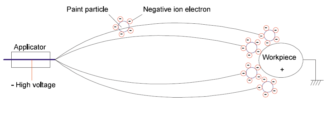
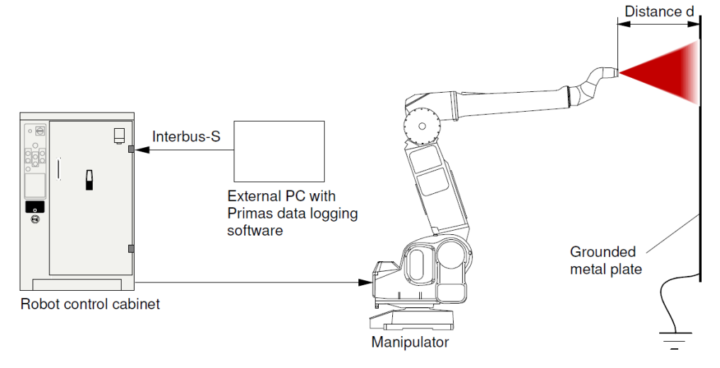
Industrial paint robots use high-voltage to perform electrostatic painting, where particles are electrically charged and attracted to the grounded paint object, as seen in Fig. 1 [5, 6]. In this way, painting quality is ensured while paint consumption and costs are minimized. However, the use of high-voltage also poses certain risks of electric shock and ignition. Fire in the painting cell may result in costly production delays, as well as damage to the equipment. Therefore, it is of great importance that the HVC works as intended.
The HVC example illustrates the fact that the complete elimination of all errors is most often not practical (due to cost and/or time constraints) or even possible. Formal verification provides us not only with a mathematically sound formalism for the specification and verification of robotic systems which ensures correctness, but also provides evidence for safety certification purposes. In fact, a survey on safety-critical robot systems [1] recognises formal verification and correct-by-construction control synthesis as two main areas needed to develop safe robot systems.
Robot control systems, like the HVC, have rather natural and generic properties that are expected to be fulfilled by any feedback controller tracking a setpoint reference. Formally verifying that overall the setpoint is followed, a system property, however, requires reasoning over the combined, time-dependent behaviour of software and hardware. For pragmatic reasons these are often modelled using diverse languages and formalisms, making holistic reasoning challenging.
Inspired by co-simulation approaches [7], in this paper we propose a novel and generic co-verification approach for pragmatic verification of system properties. Models of the software and hardware are coupled through platform mappings that define how the inputs and outputs of the software are connected to those of the hardware, in terms of its sensors and actuators. With our approach, behavioural properties of individual models – that may be established using separate domain-specific tools – can be combined to support the verification of system properties, using practical techniques, such as model checking [8].
To illustrate the use of co-verification in a representative industrial case study, the HVC software is modelled in RoboChart [9, 10, 11], while the hardware is modelled in Simulink [12]. RoboChart is a domain-specific language for model-based software engineering of robotics, with a formal semantics encompassing timed and functional aspects, that is tailored for formal verification. Simulink, on the other hand, is a de facto standard for control engineering, as typically used in industry for dynamic simulation. For co-verification we use the MathWorks Simulink Design Verifier (SDV) toolbox [12], and the CSP model-checker FDR [13], as integrated into RoboTool [9, 10, 11].
Importantly, we demonstrate the value of our approach in identifying errors that existed in an early-phase HVC software version as described in [4]. In the next phase, once the identified software shortcomings had been rectified, we were able to show that it satisfies all safety properties of concern. Namely, that overall the system tracks the high-voltage setpoint as set by an operator, and that the software resets the setpoint and disables the high-voltage if it senses that the power supply is unstable. This serves as a testimony of the strength and suitability of using formal verification methods for industrial safety-critical systems.
Some initial and preliminary results of our work regarding formal verification of HVC of industrial paint robot have been previously published in [4]. This paper extends that work by addressing some fundamental and important aspects, most notably by:
-
1.
taking into account the timed aspects of the HVC controller using the timed semantics of RoboChart.
-
2.
replacing the simplified, binary representation of the output voltage following the setpoint, with a real representation and considering timed and dynamic convergence towards the setpoint signal.
- 3.
- 4.
-
5.
using a novel approach to co-verification to combine the results from hardware simulations in Simulink with the model-checking capabilities of RoboTool [16] to verify that the high-voltage produced by the HVC follows the setpoint, a system-level safety property.
The remainder of this paper is structured as follows. Section 2 discusses related work. Section 3 provides an overview of the HVC system, contains formulations of the properties to be formally verified (Section 3.1) and presents a simplified finite state machine of the HVC (Section 3.2). Section 4 constitutes the main body of the current paper. It details the co-verification framework and explains how the state machine was modelled in RoboChart and combined with Mathworks SDV simulation and verification results in order to verify the system-level safety property concerning the high-voltage. Section 5 reports on the verification of software properties. Finally, Section 6 provides some discussion and conclusions, as well as suggestions for further research.
2 Related Work
The survey on safety-critical robot systems in [1] identifies seven areas that need further focus and research in order to develop safe, dependable robotic systems. It is notable that at least five of these areas are relevant in the context of this paper, namely: adaptive safety monitoring, modeling and simulation for safety analysis, formal methods for verification, correct-by-construction control, and certification.
A recent survey [17] maps and lists the current challenges, used formalisms, tools, approaches, as well as limitations when considering formal specification and verification of autonomous robotic systems. The main results reveal that temporal logic, state-transition and model checking are the main formalisms and approaches used during the last decade. At the same time, the lack of appropriate tools and sheer resistance to adopting formal verification methods in robotic systems development are recognised as the main limiting factors for wider impact. Likewise, the lack of interoperability and need to capture the essence of complex, industrial robotic systems using several formalisms and tools is recognised.
Simulation plays an important role in the development of robotic systems, and more widely in the domain of cyber-physical systems (CPS). However, current practice makes it difficult to soundly reason across models of the software, simulation, and hardware, which can exacerbate the reality gap. Co-simulation approaches [7, 18] bridge the heterogeneity of tools via orchestration, for example, using a common API as advocated in the FMI standard [19]. Besides the issue of code portability between tools, robotics simulators [20] tend to use different physics engines. A related approach [15] to our work on co-verification, extends the diagrammatic simulation language RoboSim [21] with facilities to cover physical modelling of robotics and establish formal links between sensors, actuators, and the software, via platform mappings.
Kawahara et al. [22] address the co-simulation of Simulink and a subset of SysML [23], where data is exchanged between models via input/output ports modelled as S-Functions in Simulink. Their focus is on testing of simulations against timed constraints expressed via sequence diagrams using the UML-MARTE [24] profile. Cavalcanti et al. [18] give semantics to a version of INTO-SysML [25], a SysML profile suitable for co-simulation using FMI, where RoboChart is used with Simulink in the co-simulation of a chemical detector robot. Bernardeschi et al. [26] use timed automata, encoded for reasoning in the PVS theorem prover [27], in co-simulation with a Simulink model of a cardiac pacemaker. Our focus, however, is on (co-)verification.
Recognising the broad range of aspects in the engineering of robots, the use of specialised, and complementary, verification techniques is widely reported in the literature. Webster et al. [28] propose a “corroborative” approach where agreement is sought between different verification techniques with respect to functional requirements, including model checking with PRISM [29], simulation-based testing and user validation.
Cardoso et al. [30] use different methods to verify components of a simulation of NASA’s Curiosity rover, where high-level control is driven by a Beliefs-Desires-Intentions (BDI) agent. The agent is verified using the Agent Java Path Finder (AJPF) model checker [31], while its interface with the environment is verified using Dafny [32]. FDR is used to verify a CSP model of the action library nodes that implement control methods following the publish-subscribe paradigm of the Robot Operating System (ROS) [33]. The emphasis is on verification of components with formal models guiding the generation of runtime monitors.
Related, Bourbouh et al. [34] report on the combined use of several methods and tools in the development of an assurance case for an inspection rover, which is modelled in AADL [35], Simulink and Event-B [36]. Functional requirements are stated using the structured natural language accepted by FRET [37], with semantics given in Linear Temporal Logic (LTL) suitable for analysis with Lustre [38] models generated from Simulink via CoCoSim [39], a framework for design, code generation and analysis of discrete dataflow models. Simulink blocks modelling the rover architecture are annotated with assume-guarantee contracts based on component requirements formalised in FRET. System-level properties are then verified via model checking with Kind2 [40], while some components are verified using Event-B instead.
The literature is rich in approaches for formal verification of Simulink models. Reicherdt and Glesner [41] propose translating discrete-time Simulink models into Boogie [42] for verifying the absence of common error classes, such as overflows, underflows, division-by-zero and range violations. CoCoSim follows on from previous work [43] targeting Lustre and SCADE [44]. Boström and Wiik [45] propose a compositional approach for verifying Simulink blocks annotated with assume-guarantee contracts.
Applications of formal verification methodologies within the control and CPS community have mainly adopted the hybrid system and automata framework of Alur et al. [46, 47]. In this setting, finite- and infinite-time reachability constitute the main verification tools, but unfortunately turn out to be an undecidable problem in general, leaving conservative set approximation as the only viable approach [48, 49]. Hybrid automata also assumes having infinite accuracy and instantaneous reaction which serves as a noticeable discrepancy to the real system and implementation; potentially invalidating the verification results [50].
Focusing on formal verification of industrial robot applications, in [3], industrial robot- and PLC-programs are compiled into PROMELA models as input for the SPIN model checker [51]. The work is however restricted to LTL formulas. It further differs from our work by solely considering deadlocks, collisions and kill-switch violations. Narrowing down to industrial paint robots, [52] considers formal verification of paint spraying using the ARIADNE tool for reachability analysis. The focus here is solely on parametric design verification.
3 High-Voltage Control (HVC)
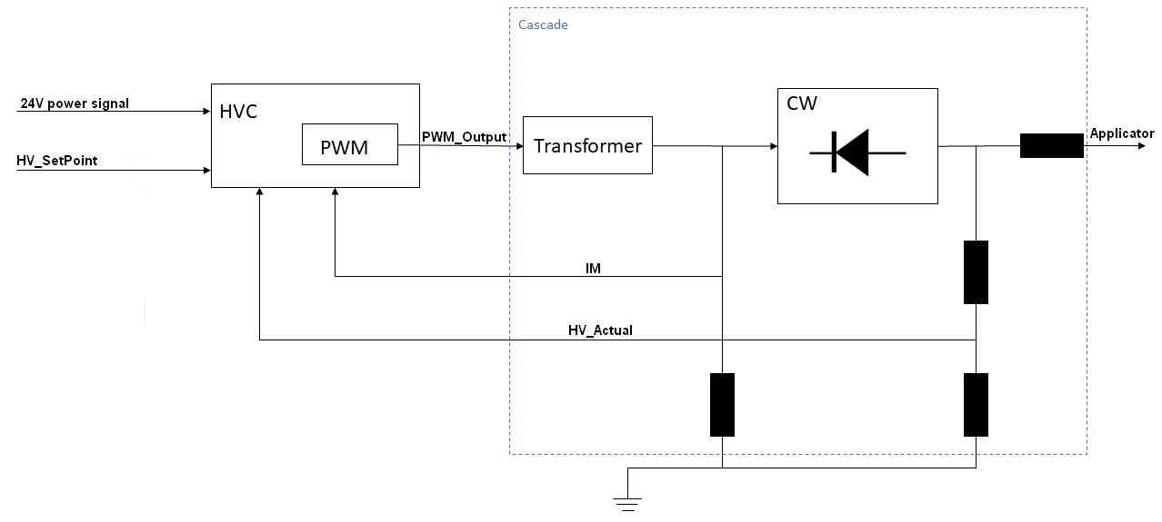
A simplified block diagram of the HVC part of the paint robot can be seen in Fig. 2. The HVC module runs the control software loops and associated control logic. Here, the signal is a function of time, t, and used as a priori given reference for the desired voltage level on the HVC, while the 24V power signal provides the HVC with electrical power. The signal serves as input signal to the Pulse Width Modulation (PWM) hardware. It is a percentage, from 0 to 100%, mapped to an analog 0 to 10 voltage signal, which is then increased in the transformer. In the Cockcroft–Walton (CW) cascade generator, there are several voltage doubling circuits, and the voltage is rectified and further increased, before arriving to the applicator, see Fig. 3. Finally, denote current and voltage measurements, respectively, which are fed back into the HVC. It is further noticeable that from a paint robot application point of view, it is given that , that is, once the high-voltage is activated and turned on, it requires values larger than , and that the reference value does not change very often, and never faster than within 10 seconds from the previous change. These facts will be used subsequently in order to formally capture and verify some basic properties for HVC.
Following the line of thought in [14, 15], in order to distinguish and describe both the control software and physical hardware components of the HVC system, a faithful model of the PWM hardware is needed. The PWM hardware comprises the components inside the dashed blue box in Fig. 2, that is, the transformer, CW cascade block and resistors.
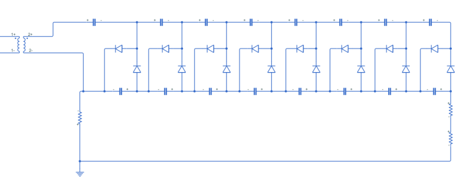
Fig. 3 depicts the diodes, capacitors and resistors defining a CW cascade block as modelled in Simulink Simscape, which allows modelling of physical components and systems. It is noteworthy that by design, each section of the CW block will double the input voltage so that the output voltage of a CW cascade with sections will equal . The Simulink models used in this work are based on and extracted from experimental laboratory tests performed in [5, 6] on real ABB paint robots as depicted in Figs. 4 and 5. This serves as a back-drop and starting point for our work.
The paint robot HVC application has some further distinguishable structure and dynamics that will need to be considered and incorporated into our formal verification scheme. As detailed in [5, 6], the PWM hardware model and cascade controller are based on three distinct modes as graphically illustrated in Fig. 6:
-
•
Charge: when a new external setpoint, HV_SetPoint(t), with higher value than the current one arrives and the PWM hardware is ramping up the control signal, , in order to increase the value of .
-
•
Running (steady-state): when has converged to and reached a steady state.
-
•
Discharge: when the external is set to a lower value and PWM hardware is discharging so that converges to .
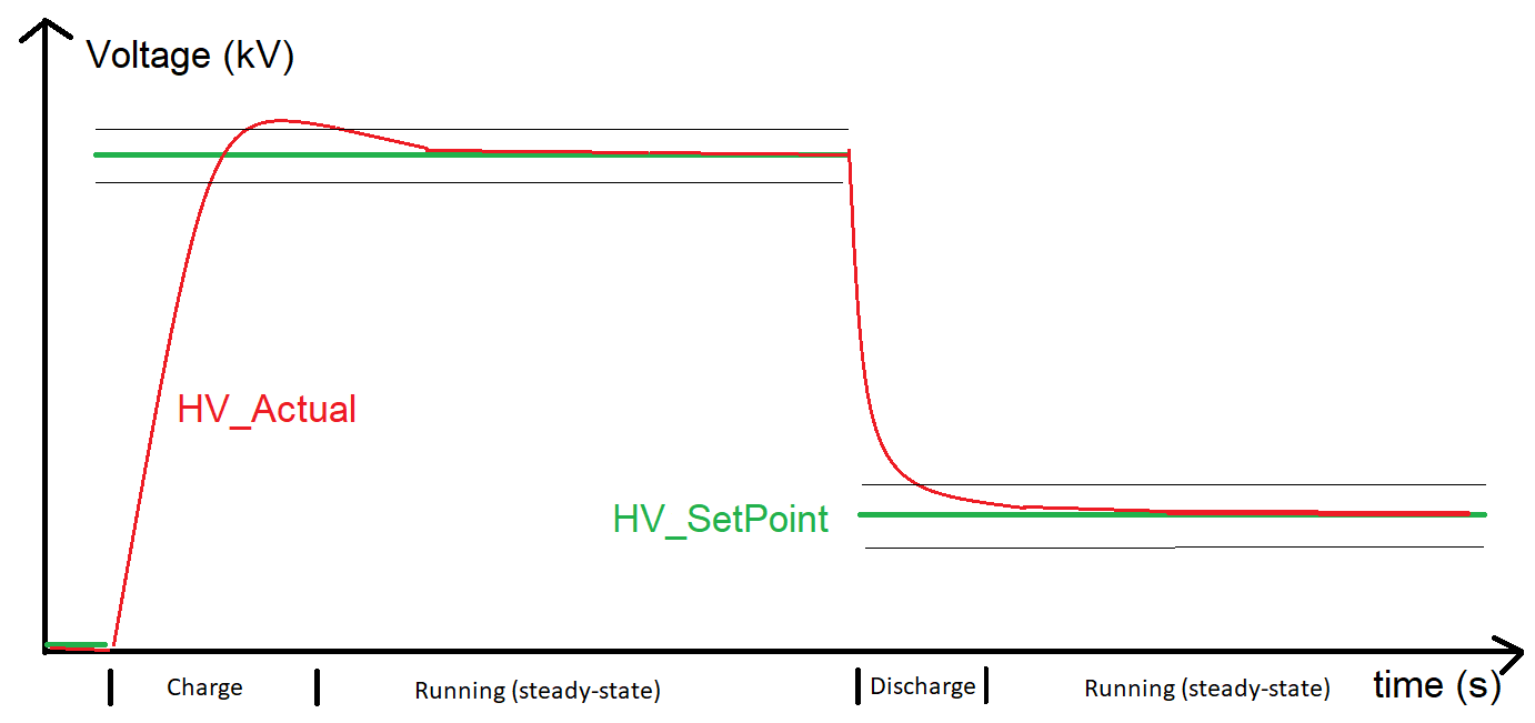
It is further noticeable that by design [53], there are additional limits on peak deviation between and as well as the time duration of the Charge and Discharge modes. Namely, a parameter RampLimit determines the maximum time in seconds that it will take to ramp up the high-voltage from minimum to maximum level, i.e., from to (kV). The default value of RampLimit is seconds. Likewise, it is known that it will take TauPeriod seconds for to reach a level of above a new lower value. The default value of TauPeriod is seconds. Additionally, there are maximum allowed over and under voltage limits. As mentioned earlier, the HVC application, once activated and turned on, requires high-voltage values larger than , so that . Consequently, the aforementioned limits are only specified at and and over/under limits at other voltage levels can be calculated using simple linear interpolation between these values. All of these parameters are used for safety supervision purposes and are hence set in a conservative manner. In the next section, these parameters will be used to formulate and later formally verify the practical convergence property of the HVC controller to a new high-voltage setpoint.
3.1 Properties for Formal Verification
In this section, the set of four properties that are to be formally verified is presented. Recognising that the HVC has a rather generic form of a feedback controller, it is notable that most of the properties in this section are rather natural and generic properties to be fulfilled by any feedback controller tracking a setpoint reference.
Property P1
To start with, it is natural to require that the measured process value, which in the case of the HVC is dependent on time, t, and denoted y(t) = HV_Actual(t), should converge to the reference- or setpoint value, . To formalize this, it is noted that both voltage signals are non-negative time-series and that convergence may be defined by setting
| (1) |
and equivalently considering (asymptotic) Lyapunov stability of the error term, , to origin.
Taking the particular structure and dynamics of the HVC application as discussed previously into account, this setpoint convergence property can in practice be decomposed into considering a 10 second time-interval directly after a new setpoint arrives, within which practical convergence of HV_Actual to a narrow interval centered around the new external setpoint (HV_SetPoint) can be shown. To ease the notation and provide symmetry between the Charge/Discharge modes, let
| (2) |
where denotes the time instance when a new setpoint arrives. Also conservatively, set the peak deviation from new HV_SetPoint as of the setpoint value. The width of this narrow interval, as well as schematic time changes and evolution of HV_SetPoint and HV_Actual are depicted in Fig. 6.
This system-level property involves both hardware and software components and can be formally specified as follows:
-
P1:
Practical convergence of the actual system voltage, HV_Actual, to the external setpoint, HV_SetPoint:
Property P2-P3
To avoid residual effects and windup behaviours in the HVC, it is also reasonable to verify that both PWM_Output and the software internal representation of HV_SetPoint, denoted mSetPoint, are set to whenever the 24V power signal, and thereby the HVC-module, is switched off. Here, mSetPoint is distinguished from HV_SetPoint which is a software extrinsic signal set a priori by a human operator or application engineer.
These two properties can be formulated as follows:
-
P2:
That PWM_Output is set to whenever the 24V power signal is off:
-
P3:
That mSetPoint is set to 0 when the 24V power signal is switched off:
Property P4
Finally, in order to increase the confidence in the correctness of the model, it is customary to verify that the HVC state machine is not able to go into deadlock.
-
P4:
That the HVC software is not able to go into deadlock.
These are the four properties that collectively need to be formally verified for the HVC application. System-level property P1 is verified using our co-verification approach, which is the subject of Section 4, while the verification of properties P2-P4, that only concern the software, is discussed in Section 5. Next we present an overview of the overall behaviour of the HVC software.
3.2 Finite State Machine Overview
In order to perform model checking on the HVC, its functionalities were modelled as a finite state machine. This section presents the general finite state machine as depicted in Fig. 7. This high-level state machine was given by ABB and then further detailed and modelled in RoboTool. This is the topic of Section 4.2.2.
In the state GateDriverRamping, which is the state that the HVC first enters when it is switched on, the PWM duty-cycle is ramped up gradually to ensure stability and gradual increasing of current and voltage. Then, in the Initialization state, initial parameters are set, as well as upper and lower limits for the high-voltage.
After the GateDriverRamping and Initialization steps are successfully finished, the state machine enters the Wait24VPower state. When the HVC has 24V power switched on and is stable, the system enters the ClosedLoop state. This is the ideal state for operation, and is where the controller is regulating the voltage in relation to the setpoint. If the voltage breaches the upper or lower limits, the state machine moves from ClosedLoop to ErrorMode.
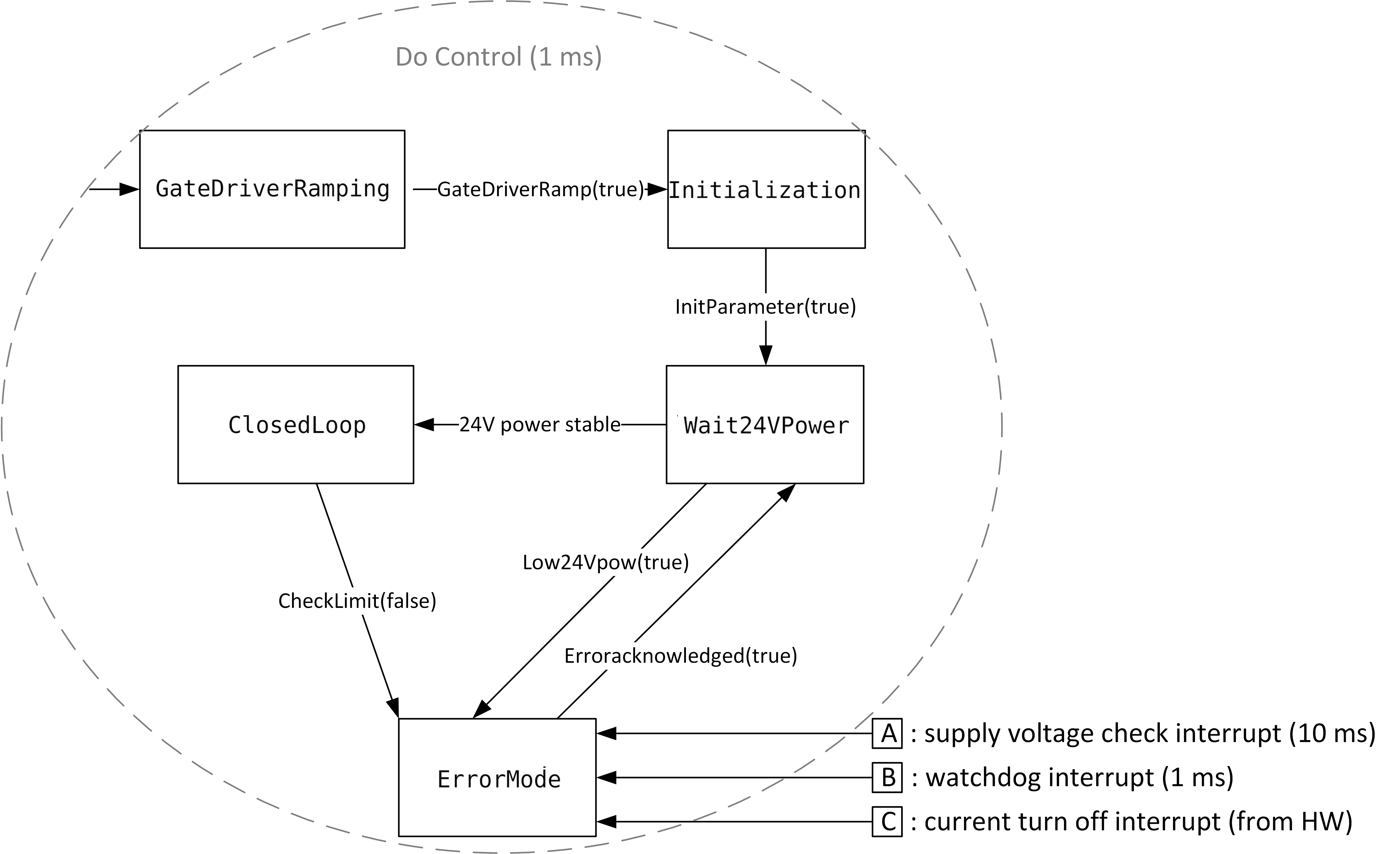
There is also a possibility to enter ErrorMode from the ClosedLoop and Wait24VPower states, if certain variables are set or any watchdogs or interrupts are triggered. For instance, an interrupt is triggered if the supply voltage is below a certain threshold, and another is triggered if HV_Actual is above or below the upper and lower limits, respectively. Getting out of ErrorMode requires manual acknowledgement of the occurred errors.
4 Hardware/Software Co-Verification
To reason about system properties, such as Property P1, it is necessary to consider the behaviour of both software and hardware. We propose a novel approach, where properties are established by co-verification of models connected via platform mappings that relate the inputs and outputs of software and hardware, via sensors and actuators. Providing a crisp and systematic separation between hardware and software has some distinct advantages. To start with, with this approach, behavioural properties of individual models – that may be established using domain-specific tools – can be combined to support the verification of system properties. Also, our approach enables explicit recording and capturing of all dependencies and relations between hardware and software, which, when neglected, are implicitly assumed to be the identity mapping. Further, and as previously mentioned, the ongoing industrial trend is moving an increasing number of safety functions from physical hardware to software implementation. Still, the reliability, dependability and trust levels are very different between hardware and software components in an industrial robotic system. This framework hence sets the stage for more realistic and refined safety and risk handling procedures. Finally, the framework invites for combined approaches to modelling both discrete and continuous aspects in an integrated way while allowing the time-scale separation that typically exists between hardware and software components.
As an illustrative example, in our case study, the software is modelled in RoboChart, while the hardware is modelled in Simulink. RoboChart [10] is a domain-specific language for the model-based engineering of control software for robotics, that caters for timed and functional aspects. Its formal semantics is tailored for reasoning, namely using the CSP [54] model checker FDR [13]. However, it currently lacks facilities to specify the behaviour of the hardware. Simulink [12], on the other hand, is a de facto standard for control engineering, typically used for dynamic simulation in the industrial setting of the HVC [5, 6] system.
For modelling, we use Simulink and RoboTool [11, 9], that allows the graphical creation of RoboChart models, and for verification we use Simulink Design Verifier (SDV) [12] and FDR. System Property P1 is co-verified by model-checking, using the formal semantics of the control software, as calculated by RoboTool, and an abstract specification of the hardware behaviour, as established using SDV. These are formalised in -CSP [54, 55], the discrete-timed process algebraic semantics of RoboChart, for checking with FDR.
The complete system behaviour is considered at a suitable level of abstraction for verification by: (1) defining a platform mapping; (2) using a specification of the hardware that captures at an abstract level the relation between its inputs and outputs, as verified using SDV; (3) formalising these in -CSP. We depict the approach in Fig. 8 and explain it in detail in the next Section 4.1. In Section 4.2 we discuss the co-verification of system properties, modelling of the hardware and software, and the mechanisation in CSP of the overall framework. In Section 5 verification of properties of the software is also discussed.
4.1 Framework overview
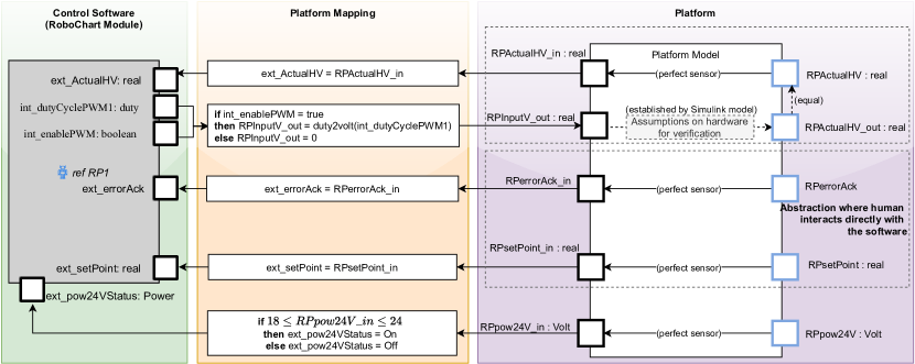
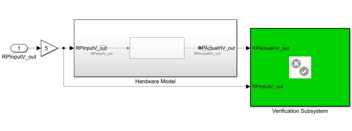
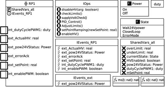
In our framework, the software and hardware models are coupled via interfaces that capture their inputs and outputs, with connections between models specified via platform mappings. On the left-hand side of Fig. 8 we consider the interface of the HVC control software, defined as a robotic platform (RP1) in RoboChart, that specifies the inputs and outputs as (possibly typed) events, indicated by solid boxes.
On the right-hand side we have a high-level description of the hardware platform, that captures its sensors and actuators. In our abstraction of the HVC platform, that comprises the cascade in Fig. 2, the hardware receives an input voltage, via RPInputV_out, and produces a high-voltage via RPActualHV_out.
We also annotate important assumptions about the hardware that are of relevance for analysis: sensors are perfect, and, in particular, the voltage produced via RPActualHV_out is assumed to be the same as that sensed via RPActualHV. The relation between RPInputV_out and RPActualHV_out is established by the Simulink model as detailed in Section 4.2.2, but abstracted for verification, as explained later in Section 4.2.4. The input signals RPerrorAck and RPsetPoint are an abstraction over the inputs available to a human operator, whose interaction with the software is realised via the platform.
The relation between the software and hardware model is specified by the platform mapping, as illustrated in the middle of Fig. 8. It records how the inputs and outputs of the software are connected to sensors and actuators of the hardware platform, as realised by low-level code and physical interfaces. The mappings for the software inputs ext_ActualHV, ext_errorAck and ext_newSetPoint are trivial, as the software reads directly from these idealised sensors. The input ext_pow24VStatus, of type Power, has the value On if the reading from the hardware, via RPpow24V_in is between 18 and 24 Volts, and otherwise has the value Off.
The software outputs int_dutyCyclePWM1 and int_enablePWM are used to determine whether a voltage is produced via RPInputV_out. If the value set via int_enablePWM is true, then the value of RPInputV_out is determined by the value of int_dutyCyclePWM1, otherwise it is 0. This captures the fact that the PWM needs to be enabled in order to produce a voltage. Here, the function duty2volt maps a percentage, from 0 to 100% to the range of the analog 0 to 10 voltage signal as previously mentioned in Section 3.
More generally, when the connection between software and hardware is realised directly via reading and writing to registers of sensors and actuators, a platform mapping can be specified by a relation. As in the case of the input RPpow24V_in, a voltage is related to a discrete set of values On and Off. On the other hand, if inputs of the software are interpreted as event-driven interrupts, a more appealing approach is to define when an event is available [15] using a predicate over the output of one or more sensors. Similarly, an input to an actuator may be constrained, for example, by a predicate over one or more software outputs.
4.2 System verification
Using the co-verification framework as illustrated in Fig. 8, in this section we address the formal verification of system Property P1. As described in Section 3.1, it requires practical convergence of the high-voltage (RPActualHV_out) to the value of the setpoint as set by the user (RPsetPoint). Since the software is modelled in RoboChart, and the hardware in Simulink, our pragmatic verification strategy consists of: (1) capturing P1 as a specification in -CSP; (2) showing practical convergence of the hardware output RPActualHV_out in relation to its input RPInputV_out using SDV; (3) casting the result obtained from SDV as a -CSP specification; (4) checking with FDR that, when combined with the semantics of the RoboChart model, via a mechanisation of the framework depicted in Fig. 8, P1 is satisfied. That overall property P1 holds is justified by the timed process algebraic semantics of RoboChart and the abstract specification (2-3) as established using SDV, and captured in CSP. A full account of the CSP specifications for all of the properties considered in this paper can be found online111https://github.com/UoY-RoboStar/hvc-case-study.
Formal Semantics
The formalism that we use, -CSP, is a dialect of the process algebra CSP, where the event marks the passage of discrete time. As CSP adopts a reactive paradigm, interactions with the environment are specified using events, and that includes the passage of time in the case of -CSP. Importantly, it allows the specification of timed budgets and deadlines, and has a denotational semantics for refinement [55]. Relevant for our work, the model checker FDR has tailored support for -CSP.
| Process | Description |
|---|---|
| SKIP | Terminating process |
| WAIT(d) | Delay: terminates exactly after d units of time have elapsed |
| STOP | Deadlock: no events are offered, but time can pass |
| USTOP | Timelock: no events are offered and time cannot pass |
| a -> P | Prefix operator: initially offers to engage in the event a while permitting any amount of time to pass, and then behaves as P |
| if g then P else Q | Conditional: behaves as P if the predicate g is true, and otherwise as Q |
| P [] Q | External choice of P or Q made by the environment |
| P ; Q | Sequence: behaves as P until it terminates successfully, and, then it behaves as Q |
| P \ X | Hiding: behaves like P but with all communications in the set X hidden |
| P |\ X | Project: behaves like P but with all communications not in the set X hidden |
| P ||| Q | Interleaving: P and Q run in parallel and do not interact with each other |
| P [| X |] Q | Generalised parallel: P and Q must synchronise on events that belong to the set X |
| P[[ c <- d]] | Renaming: replaces uses of channel c with channel d in P |
| P /\ Q | Interrupt: behaves as P until an event offered by Q occurs, and then behaves as Q |
| P [| X |> Q | Exception: behaves as P until P performs an event in X, and, then behaves as Q |
| TRUN(X) | Continuously offers the events in the set X to the environment, while time can pass |
| timed_priority(P) | Maximal progress: behaves as P with internal behaviour given priority over , so that internal behaviour takes no time |
In Table 1 we summarise the -CSP operators that we use in our work. To illustrate the notation we present a simple CSP specification of a one-place timed buffer in Listing 1 written in CSP, the machine-readable version of CSP accepted by FDR. The declaration on line 1 introduces a named type data whose values are defined by the set of integers between 0 and 2. Line 2 declares two typed channels named in and out, that can be used as event constructors using the dot notation, for example, in.0 and out.1. Related, the set of events generated by one or more event constructors can be specified as an enumerated set, so that, for example, {|in|} is equal to {|in.0,in.1,in.2|}, the set of all in events.
Processes defined within a Timed section222https://cocotec.io/fdr/manual/cspm/definitions.html#csp-timed-section (lines 6 to 9) are interpreted to be timed: events are automatically added to allow time to pass when waiting for interactions with the environment, and the passage of time is uniform across interacting processes. The function OneStep, defined on line 4 to be 0 for every event in its domain (indicated by the underscore in its signature), is passed as a parameter (line 6) to the Timed section to ensure that no time is added implicitly after every synchronisation with the environment.
The behaviour of the timed buffer is that defined by the process Example (line 7) that behaves as TimedBuffer with timed_priority applied, a function over processes, provided by FDR to calculate the correct timed semantics [55]. TimedBuffer (line 8) initially offers to receive a data value via a prefixing on the channel in, and then offers an external choice ([]) to the environment between accepting a new value, via the recursion on TimedBuffer, or delaying the output of the current value, via prefixing on out after the sequential composition (;) with a delay of one time unit (WAIT(1)). We observe that an external choice is not resolved by the passage of time, but rather by synchronisation on events. Here, in?x is syntactic sugar for accepting events in.x where x ranges over the type data. The prefixing on out!x takes the value of x as introduced into context by the prefixing on in?x.
Specification
Following the description of P1 in Section 3.1, here we construct a discrete version in -CSP, as shown in the RoboChart timed csp block named SpecP1 in Listing 2. It declares two channels (line 2), e and RPsetPoint, of type core_real. The event e is used to model the absolute difference between ActualHV_out and RPsetPoint, so that the specification can capture the relation between changes in RPsetPoint and the absolute difference.
The behaviour of SpecP1 is that of Follow, a process with a single parameter d, defined on lines 6 to 12 as an external choice ([]) over accepting events e or RPsetPoint, via prefixing (?x ->). Synchronisation on RPsetPoint, with any value, or e, with value 0, is followed by a recursion on Follow. Whenever the event e carries a value that is not 0 (lines 8 to 9), then Follow behaves as the process ADeadline({|e|},{|e.0|},d), that ensures an event e with a value of 0 can only be observed within d time units (instantiated as 3s for SpecP1), and afterwards behaves as TRUN({|e.0|}). This behaviour can be interrupted (/\ on line 9) at any time by a new RPsetPoint. We observe that for the purpose of model-checking the reals, modelled by the type core_real, are instantiated in the discrete domain 0 to 2, so here we consider the difference , encoded via the event e, to be 0, without loss of generality.
The auxiliary process ADeadline(S,E,d), defined on line 16, takes three parameters, two sets of events, S and E, where S is expected to be a subset of E, and a natural number d. It continuously offers events in the set S, but time can only advance by up to d units, unless an event from the set E happens, in which case the process terminates. It is defined using the exception operator of CSP ([|E|>), where initially the behaviour is that of EndBy(TRUN(S),d), that continuously offers events in set S, and allows time to advance by up to d time units. Thus, within the exception, if TRUN(S) performs an event that is in E, then the process behaves as SKIP, that terminates immediately.
We observe that the auxiliary processes TRUN and EndBy are included with the RoboTool distribution for convenience. EndBy(P,d), reproduced on line 19, is a deadline over process P to terminate within d time units. It behaves as P, but because time is uniform in -CSP it requires the right-hand side process WAIT(d);USTOP to agree on the passage of time. That process, however, is only prepared to let d time units to pass before it timelocks, effectively imposing a deadline. Next, we focus on the hardware model.
4.2.1 Hardware Modelling and Verification in Simulink Design Verifier (SDV)
Both the co-verification regime detailed in Section 4.1, as well as verification of the system-level properties, require a distinct and systematic separation between hardware and software components of the HVC system. Fig. 8 provides an overview of this separation and the steps toward implementing this have been set forward in the ingress of Section 4. To this end, the focus of this section is centered around hardware modeling, specification, abstraction and verification of hardware properties in SDV. All of these components are naturally combined in order to co-verify system-level properties.
Simulink is widely adopted as a tool for traditional, input-driven simulation, and the modelling in SDV is similar to regular modelling used for simulation [12]. SDV uses Prover Plug-In® products from Prover® Technology to do model-checking and prove the model properties [56]. It is built upon Gunnar Stålmarck’s proof procedure, which uses tautology checks to prove that an assertion holds true in every possible interpretation [57]. In Property Proving mode, SDV offers three different proof strategies, Prove, FindViolation and ProveWithViolationDetection where the latter is merely a serial combination of the two first mentioned. In this work, both Prove and FindViolation have been used. Prove performs an unbounded property proof, while FindViolation searches for property violations within the number of steps specified by the Maximum violation steps option, which specifies the maximum number of steps that SDV searches for property violations. Thus, verification with increasingly large Maximum violation steps will help to increase confidence in the property.
The Simulink Model
The hardware model in Simulink was created based on previous models found in [5, 6]. These models have been validated both theoretically and empirically by several lab experiments, and correspond well to the real-world system. In order to do formal verification with SDV however, the model had to be converted from continuous to discrete time, since SDV does not support continuous time. In this process, in addition to converting transfer functions specified in continuous time using Laplace transform (S-domain) to discrete time Z-domain, some of the Simulink blocks specific to continuous time were replaced with their discrete counterparts. Fig. 9 shows the overview of the hardware verification model in SDV where the input/output signals, i.e., RPInputV_out and RPActualHV_out denote the same signals as previously introduced in Section 4.1 and Fig. 8. The mapping and transfer function between these two signals, and formal verification of certain hardware properties treated in this section, then correspond naturally to the extension and scope of the dashed grey box on the upper right side of Fig. 8.
It is noteworthy that, the input, RPInputV_out, ranges over the discrete domain, , and is multiplied by a constant factor 5 in Simulink, effectively corresponding to having the set of possible values of volt being fed into the PWM hardware model. This means that duty2volt maps a percentage, from 0 to 100% to the entire range of the analogue voltage signal as previously mentioned in Section 3. It also implies that the convergence results obtained in this section using volt as input, will also be valid for the real PWM hardware system. This is because its input set, , is a superset of .
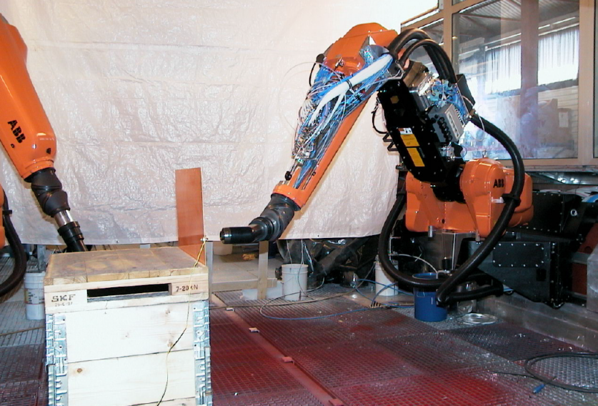
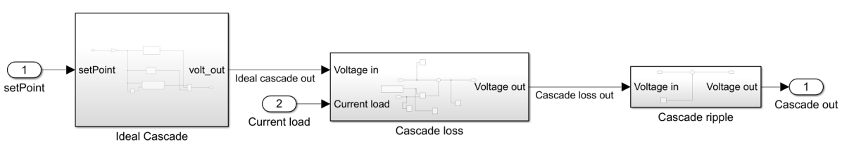
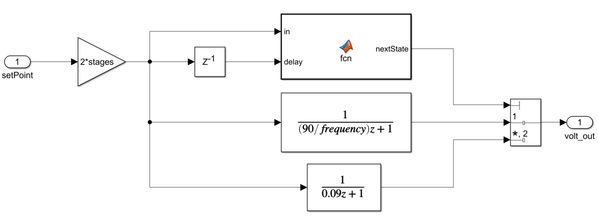
The test data used to create the model was collected from structured experiments running at many different HV setpoints, frequencies, distances and number of stages in the CW-cascade, providing a rich data-set to represent how the actual hardware will behave in the real environment. As detailed in [5, 6] and depicted in Fig. 10, the Simulink model will, in addition to the ideal transfer function, have two additional terms describing the cascade loss and ripple effects. Using the Matlab System Identification Toolbox, state-space models and transfer-functions are fitted to the lab test data to provide the best description of the PWM hardware dynamics; both during the charge and discharge modes of operation. The resulting transfer functions and model components in continuous time can be seen in Fig. 10. Additionally, a Simulink model describing the bell-cup inside the applicator that will effect the electrical field at a plane at a given distance, , from the paint robot, has been derived in [5] and used here.
In order to be able to formally verify the system-level property, P1, the mapping and relational properties between RPInputV_out and RPActualHV_out, effectively describing the hardware, is needed. This allows us to obtain a well-defined “closed circuit” mapping between all of the components in the co-verification framework of Fig. 8. To this end, the System Identification Toolbox was used to model the transfer function describing the relation between these two signals. This resulted in a standard, second order transfer function model:
| (3) |
having the following specific parameters
This model was then analysed in Simulink with particular attention to time dynamics, stability and convergence properties as defined by, e.g., rise and settling-time. Of particular interest in the following, is the settling time, , which was found to be .
Formal Verification of Hardware Properties
Based on the developed Simulink model, next, we will be verifying a low-level property that will then be used in the co-verification scheme in order to verify Property P1.
Referring back to the definition of Property P1, the error term Eq. 1 as well as the notion of practical convergence in Section 3.1, the following hardware property will be considered and verified in this section:
Practical convergence of actual hardware output voltage, RPActualHV_out, to the hardware input signal, RPInputV_out, within settling time, :
| (4) |
Here, denotes the time instance where an update to the input, RPInputV_out, is received in PWM hardware. It is notable that while Property P1 is a system-level property, involving both software and hardware components, Property as defined by Eq. 4 serves as a low-level hardware property. Another important distinction, stems from the difference in value between the settling time, , in Eq. 4 and in Eq. 1 which implies that incrementally contributes towards fulfilment of corresponding equations to verify the overall convergence Property P1. This fact also underlies and explains the difference in peak deviation limit (0.15 and 0.3 respectively) between the two properties.
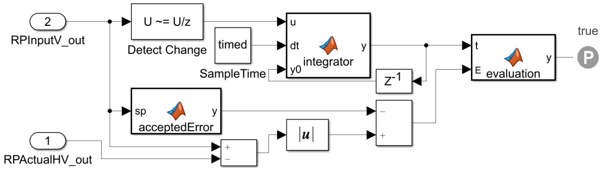
The Simulink implementation to verify this property lies within the green Verification Subsystem in Fig. 9 and has been depicted in Fig. 12. The upper part containing the Detect Change block and an integrator function, works as a timer that is reset every time there is a change in RPInputV_out. This in order to capture the constraint in Eq. 4. The lower part takes the absolute value of the error between RPInputV_out and RPActualHV_out and subtracts the accepted error, which is set to . Finally, the last function on the right, denoted evaluation, gives out false if Eq. 4 is not fulfilled at any time instance, . Otherwise it gives out true. This is verified with the proof assumption block, which shows if the property is fulfilled or violated.
After creating the model and the specification, the Prove strategy was used in order to verify the property. It was run both using MATLAB online and on a Windows laptop with Intel® Core© i5 CPU @ 2.71GHz. The online version and the desktop version were both used in order to run two verifications in parallel, to see if one would produce a result faster than the other. However, after running both continuously for 10 days without producing a result, the verification was manually terminated, with the assumption that the complexity had resulted in a state-space explosion that made Simulink unable to verify the specification. It was instead decided to gain increased confidence in the verification by using FindViolation with increasing Maximum violation steps. The results of the verification by using FindViolation can be seen in Table 2. The Maximum violation steps option was gradually increased, until reaching the maximum value of 2,147,483,647, which is the maximum value for data type int32. As seen in the table, SDV was able to prove that the property was valid within bound in all cases.
| Maximum violation steps |
|
Result | Elapsed time | ||
|---|---|---|---|---|---|
| 1,000 | Valid within bound | 0:47:49 | |||
| 1,000,000 | Valid within bound | 0:46:44 | |||
| 1,000,000,000 | Valid within bound | 0:47:15 | |||
| 2,147,483,647 | Valid within bound | 0:47:15 |
4.2.2 Software Modelling in RoboChart
In this section, we present the RoboChart model of the software, that is a formalisation of the sketch previously shown in Fig. 7. The robotic platform (RP1) – a specification of the services available to the software in terms of variables, events and operations – is fully specified in Fig. 13. Its events are defined in the interface IEvents_RP1. RP1 also provides the interface SharedVars_all, that declares all of the shared variables that are used in the model. The interface IOps specifies the signature of the software operations that are used, and defined, in the RoboChart model. In addition to employing built-in data types, such as reals, naturals, and booleans, three data types are declared: the enumerated types Power and State, and the given type duty. Two functions ms and s are used to construct time units corresponding to milliseconds and seconds, respectively. RoboChart adopts the type system of Z [58, 59]. For a full account of the language and its formal semantics we refer the reader to [11, 16, 9]. Here, we describe the RoboChart constructs as we use them to model our example.
 \cprotect
 RP1), interfaces (named IOps, IEvents_RP1, IEvents_ext, and SharedVars_all), enumerated (Power and State) and given (duty) data types.
  is an event,
  is a variable, and
  is associated with an operation.
  is used to record that an interface is provided, while
  is a used interface.
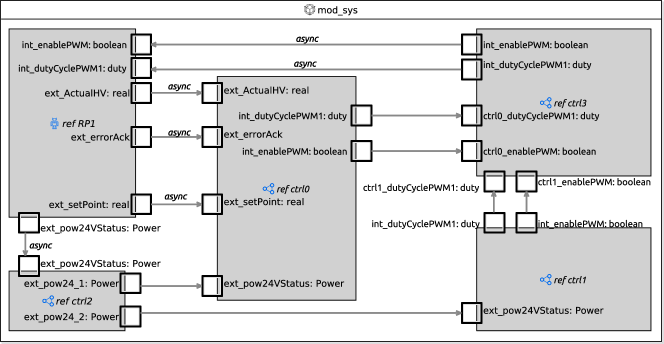
Module and Controllers
The top-level component of the software model is defined by the RoboChart module mod_sys, shown in Fig. 14. It associates the robotic platform with four controllers (ctrl0-3), that capture specific behaviours. Controller ctrl0, shown in Fig. 15, contains the main State_machine, that is a recast of that presented in Fig. 7, ctrl1 captures the behaviour of the watchdogs, and controllers ctrl2-3 are used to relay events. Controller ctrl2 relays the input event ext_pow24VStatus from RP1 to controllers ctrl0-1, and ctrl3 relays the output events int_dutyCyclePWM1 and int_enablePWM from ctrl0 and ctrl1 to RP1, as RoboChart event connections are point-to-point. Due to their simple nature, the full definition of all controllers is deferred to an on-line report333https://robostar.cs.york.ac.uk/case_studies/hvc/. In RoboChart, connections with the platform are always asynchronous, indicated by the keyword async, as interactions with the platform cannot be refused, only ignored [10, p.3110]. The connections between all controllers ctrl0-3, however, are set as synchronous.
State Machine
The core behaviour of the HVC controller is captured by the State_machine in Fig. 16. In RoboChart, state machines are self-contained by explicitly stating the required (![]() ) variables and operations, and the used (
) variables and operations, and the used (![]() ) events. In this case, State_machine requires the software operations declared in IOps, and the shared variables in IVars_seqSM_shared. It also declares: local variables via the interface IVars_seqSM, a constant cycleTime with a default value of 10 milliseconds, and a clock (
) events. In this case, State_machine requires the software operations declared in IOps, and the shared variables in IVars_seqSM_shared. It also declares: local variables via the interface IVars_seqSM, a constant cycleTime with a default value of 10 milliseconds, and a clock (![]() ) Cl1. It uses the events of interface IEvents_ctrl0, that are also explicitly listed on the left-hand side of Fig. 16.
) Cl1. It uses the events of interface IEvents_ctrl0, that are also explicitly listed on the left-hand side of Fig. 16.
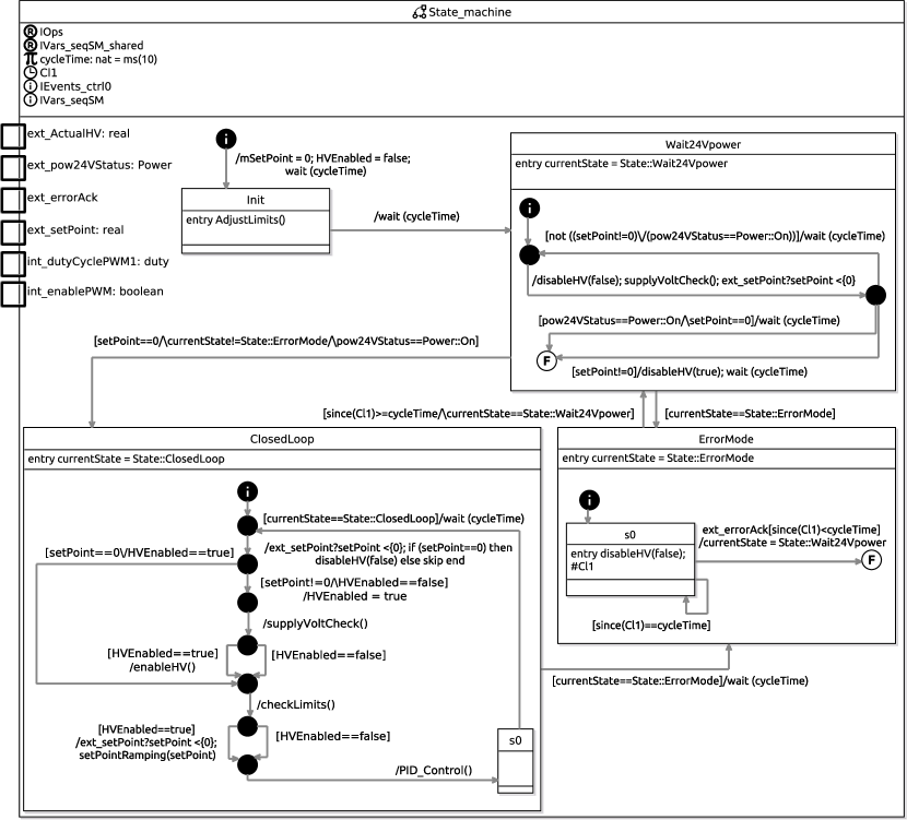
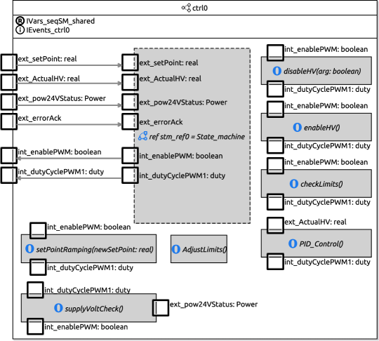
The execution flow of State_machine starts at the initial junction, followed by a transition whose action, specified after the dash (/), initializes the value of the variables mSetPoint and HVEnabled, by assigning 0 and false in sequence (;), respectively. It then waits for cycleTime units before entering state Init. This initial delay is a simplification of the GateDriverRamping behaviour depicted in Fig. 7, which does not concern the properties of interest for verification. In state Init there is an entry action that calls the software operation AdjustLimits which calculates the value of variables overLimit and underLimit and is defined by a state machine as shown in Fig. 17. The required variables of AdjustLimits, as listed in interface IVars_adjustLimits, are provided by State_machine in the context of the call to AdjustLimits, effectively sharing the state.
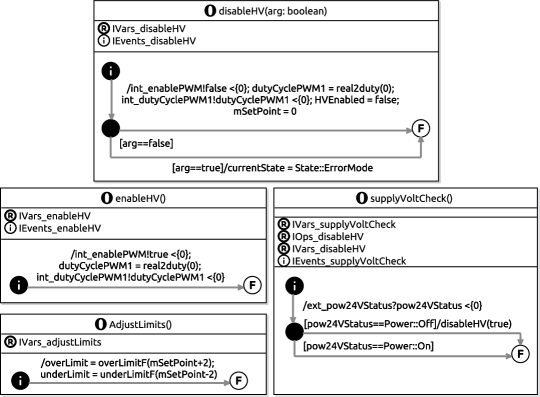
After the initialization is complete, the execution proceeds to the composite state Wait24Vpower on the next cycle. Its entry action explicitly records that the state has been entered by setting the variable currentState. The transition to ClosedLoop is only enabled when the current value of setPoint is 0, the 24V power is stable (pow24VStatus==Power::On), and the ErrorMode is not activated, as indicated by the transition’s guard. The body of Wait24Vpower monitors the relevant inputs periodically as part of the cycle of transitions between the junctions. Firstly, the operations disableHV and supplyVoltCheck, as defined in Fig. 17, are called. disableHV disables the high-voltage, while supplyVoltCheck checks the input ext_pow24VStatus and updates the value of the variable pow24VStatus. Secondly, the value of the variable setPoint is also updated via a reading (ext_setPoint?setPoint) through event ext_setPoint, with a deadline (<{0}) of zero time units. In RoboChart budgets and deadlines must be specified explicitly, and so here the deadline indicates that the reading takes a negligible amount of time.
The critical phase of HVC operation is captured in state ClosedLoop, that controls the PWM. Initially the user-defined setpoint, ext_SetPoint, is read into the variable setPoint. If the value is zero, then disableHV is called to ensure that the high-voltage is disabled. Afterwards, if the value is non-zero and the high-voltage has not been enabled yet (HVEnabled==false), HVEnabled is set to true, the supply voltage is checked by calling supplyVoltCheck(), and the high-voltage is enabled by calling enableHV. While the high-voltage is enabled, the internal setpoint (recorded in variable mSetPoint) is adjusted by calling setPointRamping(setPoint). The PWM duty-cycle is adjusted by PID_Control that outputs a percentage via int_dutyCyclePWM1, according to the difference between mSetPoint and ActualHV, the measured high-voltage via the input ext_ActualHV. In state s0 of ClosedLoop, the flow of execution may be interrupted by transitioning to ErrorMode when currentState is set to State::ErrorMode. The error can be acknowledged via the event ext_errorAck within the current cycleTime, after which there is a transition to Wait24Vpower.
The variable currentState may be set to State::ErrorMode by calling disableHV(true), either while in Wait24Vpower, or from within operations checkLimits or supplyVoltCheck, that checks whether the input 24V power is stable. The latter is called regularly in states ClosedLoop and Wait24Vpower of State_machine, and also by the watchdog, which, as will be explained next, is modelled in another state machine.
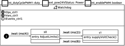
Watchdog
The watchdog, shown in Fig. 18, executes, over time, in alternation with the main State_machine, that executes on a 10 millisecond cycle, as specified by the constant cycleTime. Therefore, the watchdog’s behaviour is initially delayed by 4 milliseconds. In state s0 there is a call to AdjustLimits(), and 2 milliseconds later, the operation supplyVoltCheck() is called. We observe that the transition between s1 and s0 takes 8 milliseconds, and it is during this time that State_machine actually executes its cyclic behaviour.
4.2.3 Framework Mechanisation
Having developed models of the software and hardware, in this section we mechanise the co-verification framework outlined in Fig. 8 with the aim of verifying system Property P1. We start by defining a CSP process that captures Property . This is followed by the complete mechanisation of the platform and its mapping, and the composition with the semantics of the RoboChart model, as calculated by RoboTool.
Platform
The hardware platform is specified within the csp block named HVC_Platform, shown in Listing 3. It defines, first of all, the CSP events of the sensors and actuators (lines 4 to 9), following the naming conventions of Fig. 8. The process HVC_Platform is a discrete, and reactive, model of the hardware, constructed from the Property established in Section 4.2.1. It is defined as a parallel composition ([| |] on lines 14 to 16), synchronising on event set_HV, of HV(0), that models the current value of the high-voltage, and HVC_Hardware, that captures how the value of RPActualHV_out may change over time in response to changes in RPInputV_out. The process HV(x), defined on line 19, offers the event set_HV to change the value, and the event get_HV to query the current value x. It is specialised on line 14 as HV(x)[[ get_HV <- RPActualHV_out ]] by renaming the event get_HV to RPActualHV_out. The event set_HV is hidden (\), as it is an artefact of the CSP model.
The evolution of the value available via RPActualHV_out is modelled by the process HVC_Hardware. It is defined on line 21 as the parallel composition of the process Detector, synchronising on the events change and get_HV, and the process StatefulEvolution. The latter models how changes to the voltage evolve over time, while Detector, named analogously to the SDV block in Fig. 12, models how an input via RPInputV_out may affect the behaviour. First it offers to receive a new value nv via RPInputV_out, and then synchronises with StatefulEvolution on get_HV to query the current value x being targeted. If the value is different, it synchronises on change with value nv, otherwise it behaves as Detector.
The core of the hardware property is abstractly captured by the process StatefulEvolution. It is defined on line 27 as the parallel composition of Evolution, synchronising on event change, with HV(0) where the channel set_HV is renamed to change. Evolution accepts a change event at anytime, and afterwards waits 370 milliseconds, a conservative natural approximation of the settling time of the Simulink model of the hardware, before synchronising on set_HV, which is used to update the high-voltage, whose value is available via RPActualHV_out, as modelled by the process HV(0) in HVC_Platform. Thus, a change via RPInpuV_out leads to a change in the value available via RPActualHV_out over time, mirroring property as established in Section 4.2.1. Next, we describe the mechanisation of the platform mapping.
Platform Mapping
The process PlatformMapping, defined on line 7 of the csp block in Listing 4, captures the non-trivial mapping between int_dutyCyclePWM1, int_enablePWM, and RPInputV_out, and between RPpow24V_in and ext_pow24VStatus. It is an interleaving (|||) of two processes, Pow24V_Map, that models the mapping between RPpow24V_in and the software input ext_extPow24VStatus, and the prefixing on RPInputV_out with value 0 followed by the behaviour of PWM_Map. Here the prefixing initializes the hardware with value zero. PWM_Map, defined on lines 10 to 15, models the mapping between the outputs int_dutyCyclePWM1 and int_enablePWM, and the input to the platform RPInputV_out.
PWM_Map is parametrised to keep track of whether the PWM has been turned on or off. The first process in the external choice (lines 11 to 12) allows this value to be toggled depending on whether int_enablePWM.out is received with value false, in which case the value zero is passed to the platform via RPInputV_out, and otherwise there is a recursion on PWM_Map(x) with the updated value of x. In the second process (lines 14 to 15), values received via int_dutyCyclePWM1.out are passed to the platform via RPInputV_out, mapped via the function duty2volt, if the value of pwm is currently true. This function, defined on lines 3 to 5, maps a percentage to a voltage, which, as previously discussed in Section 4.1, encodes three possible values.
The CSP process Pow24_Map is defined analogously on lines 18 to 25 to model the mapping between the sensor of the 24V voltage, and the input ext_pow24VStatus of the software, whereby a value between 18 and 24 is considered as On and otherwise as Off. The value that x can take on the prefixings on the channel RPpow24V_in, on lines 19 and 21, is constrained using set comprehensions. This concludes the non-trivial mappings, which are used in the definition of the overall system next.
Mapped System
The complete system, as envisioned in Fig. 8 is modelled by the process MappedSystem within the csp block of Listing 5. It is defined on lines 20 to 24 as the parallel composition of MappedSoftware and HVC_Platform, defined in Listing 3, synchronising on the events RPInputV_out and RPActualHV. Here HVC_Platform is relationally renamed [54, p. 105], so that the event RPActualHV_out is both an output of the platform and also a sensor input, with the same value, via RPActualHV, as depicted in Fig. 8. The hiding on RPInputV_out and RPActualHV completes the abstraction.
The process MappedSoftware, defined on lines 15 to 18, captures the connections between the composition of the platform mapping and the software, as established by Software_PMap, and the platform, by renaming the events of the former to the latter. The sensors of the platform, in particular, are assumed to be perfect, and so in this abstraction the functional renaming is a record of their ideal functional behaviour.
Sofware_PMap, defined on lines 7 to 13, captures the composition of the RoboChart CSP semantics, and the PlatformMapping, as defined earlier in Listing 4. It is a parallel composition of the processes Software and PlatformMapping, synchronising on int_enablePWM.out, int_dutyCyclePWM1, and ext_pow24VStatus, corresponding to events of the RoboChart model. The process Software, which explicitly instantiates the RoboChart model semantics, is defined analogously to MappedSoftware, whereby the trivial mappings are captured via renaming. The hiding on line 13 completes the abstraction.
The process mod_sys::O__(0,ms(10),1), used on line 4, is an explicit instantiation of the CSP semantics of mod_sys, automatically calculated by RoboTool, where 0 is a default identifier, ms(10) is the value of constant cycleTime of State_machine, and 1 the value of constant rampStep of operation setPointRamping. Events in the CSP semantics of RoboChart are named according to the model hierarchy, where :: is a delimiter, and have a parameter in or out to indicate whether an event is an input or output.
4.2.4 Formal Verification of System-level Property P1
With the framework outlined in Fig. 8 mechanised in CSP, in this section we address the verification of Property P1. Its specification in CSP, described in Section 4.1, is reproduced in Listing 6 for convenience. Verification of Property P1 is stated as a refinement assertion P1 in the traces model of CSP (line 15), that ensures safety [54, p.36]. That is, an implementation P refines Spec, if, and only if, every behaviour of the implementation is a behaviour permitted by the specification. While RoboChart assertions are translated by RoboTool into CSP refinement assertions, they can also directly reference elements of the RoboChart model to facilitate the checking of basic properties, such as deadlock freedom and termination [10, p. 3129]. For assertion P1, SpecP1 is the specification and ImplP1 is the implementation. As previously discussed in Section 4.1, SpecP1 is stated in terms of a new event e, that is not part of Fig. 8 but useful to specify Property P1 in terms of the absolute difference between the value of output RPActualHV_out and input RPsetPoint. To facilitate verification, process ImplP1, is defined next to relate events e and RPActualHV_out, and RPsetPoint, based on the process MappedSystem, previously defined in Listing 5.
System Interface for Verification of P1
We observe that in SpecP1, the event RPsetPoint is used as an interrupt, which emerges naturally in the reactive CSP setting. However, the event RPsetPoint as used so far in the definition of MappedSystem models readings of a sensor, that can be performed periodically despite no change in the actual value. Therefore, to relate SpecP1 and ImplP1, in Listing 7 we define a suitable mapping for the RPsetPoint event. We also capture the relationship between the event e and the current value of both the setpoint and the actual high-voltage, as required for the comparison with SpecP1.
Moreover, we also explicitly capture three assumptions, that are implicitly required for the verification of P1: (1) the 24V power is stable, as reported via the input RPpow24V (2) no error is to be acknowledged via RPerrorAck (3) the HVC control software is correctly initialised, that is, RPsetPoint has a value of zero during the first two cycles of State_Machine, so as not to trigger an error, and that the value of RPsetPoint changes no more often than once per second. It should be noted that this third assumption regarding the frequency of change of RPsetPoint, is more conservative than necessary, as RPsetPoint is known to never change faster than within 10 seconds from the previous change, as mentioned in Section 3. These assumptions together define the normal working behaviour of the HVC, where the State_machine operates within the ClosedLoop state, during which P1 is required to hold.
Process ImplP1 is defined on line 49 of Listing 7 as the parallel composition of ESystemP1, synchronising on event RPsetPoint with Assumption_SetPoint (line 9). The latter captures the first assumption by requiring that initially the setpoint is set to zero, with immediate effect, via the use of the EndBy construct of -CSP, and where, after 22 milliseconds, its value can change arbitrarily, at most once per second, as defined by the process RPChange on line 10. Here 22 ms corresponds to at least two cycles of the execution of State_machine, given that for verification we consider each time unit as encoding 2ms, and that cycleTime is instantiated as 10ms. The process ESystemP1 introduces the event e in the context of the system behaviour, as defined by RPSystemP1 on line 19, that captures the other two assumptions and relates the RPsetPoint of Fig. 8, a sampled input, with the RPsetPoint of SpecP1, which is used as an interrupt for the purpose of specification.
ESystemP1 is defined on lines 43 to 46 as the parallel composition of RPSystemP1 and two processes Error and Sampler, that are also composed in parallel, synchronising on RPsetPoint and RPActualHV_out. The process Error synchronises on these events so that it offers to synchronise on event e with a value given by the absolute difference, specified by the application of abs_diff on line 35. This follows the definition of Property P1 as presented in Section 3.1. The process Sampler ensures that the actual high-voltage, read via RPActualHV_out, and the difference, via e, are updated exactly every time unit. This is specified by imposing a deadline of zero time units on the prefixing of RPActualHV_out and e, using a deadline, followed by a delay of exactly one time unit. This is a modelling mechanism to ensure that the events corresponding to sampled inputs or outputs, namely RPActualHV_out, are updated regularly without introducing erroneous Zeno behaviours, that is, to prevent the CSP model from making an infinite number of updates within a finite amount of time.
The process RPSystemP1 is defined as a parallel composition (line 19) of the process SystemP1, where the event RPsetPoint is renamed to a new event int_RPsetPoint, used in the synchronisation set, with RPEventMapping(0). The latter process takes in new values via RPsetPoint, and then offers to synchronise on int_RPsetPoint with the same value. The hiding of event int_RPsetPoint makes it possible for SystemP1 to query the setpoint value periodically via int_RPsetPoint, rather than directly via RPsetPoint, as required for the comparison with SpecP1. This is a modelling mechanism to ensure the event RPsetPoint can be treated in the interrupt style of SpecP1.
Finally, SystemP1, defined on lines 13 to 15, is the composition of the behaviour established by the co-verification framework, that accounts for the software and hardware modelling, as defined by MappedSystem and processes Assumption_RPerrorAck and Assumption_RPpow24V that capture the second and third assumption for the purpose of verifying Property P1. Here Assumption_RPpow24V (line 8) initially sets the input RPpow24V to the value 24, while Assumption_RPerrorAck (line 7) refuses to acknowledge any error via RPerrorAck by behaving as STOP, the process that deadlocks. As before, the use of hiding, on lines 13 and 15, completes the abstraction as the events RPerrorAck and RPpow24V are not relevant for refinement checking of SpecP1. Next, we report on the use of FDR for checking the timed assertion P1.
Verification Parameters and Results
For model-checking with FDR, not only constants of the RoboChart model have to be instantiated, but the domain of the data-types must also be defined as discrete finite sets. These are defined in a special csp block named Instantiations, reproduced in Listing 8.
Besides, in this block we also give a CSP definition for all of the functions declared in the RoboChart model. overLimitF and underLimitF, used by the software operation AdjustLimits, ensure that the result is closed under the type. Since in the software model all time units are divisible by 2, the smallest time unit is chosen as encoding 2 milliseconds, thus the function ms, halves the argument, and s, encoding seconds, is defined analogously.
The reals are instantiated as the set as this is a realistic representation of the different inputs and outputs, namely RPsetPoint, where values from 0, 1 and 2 naturally map to high-voltage values 0, 40 and 80 kV. Recall that, from a paint robot application point of view, it is given that once the high-voltage is activated and turned on, it requires values larger than , i.e., . Hence by switching between the values 0, 40 and 80 kV, we are able to capture all possible qualitative combinations for HV setpoint changes (i.e., charge/discharge as well as increase/decrease in setpoint). Based on this, it is observed that the set provides a rich enough representation of the system inputs.
The timed assertion P1 is successfully verified by FDR. On a dual AMD EPYC 7501 32-core machine with 1TiB of RAM, it took FDR 2850s overall to verify that the property holds (1456s to compile the Labelled Transition System (LTS), and 1394s to verify the refinement), having visited 126,481,225 states and 517,333,656 transitions. For comparison, in Table 3, we include this result together with those concerning only the verification of software properties, which we address next.
5 Formal Verification of Software Properties
In what follows we discuss the verification of properties P2-P4 of Section 3.1, which concern only the software. Property P4 concerning deadlock freedom can be specified directly using the assertion language provided by RoboTool. Properties P2 and P3, on the other hand, are specified directly in CSP.
Property P2
Taking into account the RoboChart model, P2 can be restated as requiring that the observation of the input ext_pow24VStatus with value Power::Off is followed by the output int_dutyCyclePWM1 with value 0. As CSP adopts a reactive paradigm, the process SpecP2, specified in Listing 9, is defined in terms of events. It considers the case when the output int_dutyCyclePWM1 has been set to a value other than zero and subsequently ext_pow24VStatus is observed with value Power::Off.
The behaviour of SpecP2 is that of PWM_off, defined on line 11 as an external choice over behaving as PWM_Behaviour or accepting the event mod_sys::ext_pow24VStatus.in.Power_Off, followed by the recursion on PWM_off. PWM_Behaviour tracks the changes of the output int_dutyCyclePWM1 by offering a value greater than 0 and then behaving as PWM_on, or, a value of 0, and then behaving as PWM_off. In PWM_on (lines 15 to 20) we capture the core of Property P2, where, following the event mod_sys::ext_pow24VStatus.in.Power_Off we require mod_sys::int_dutyCyclePWM1.out.0 to be observed within 10 milliseconds (matching the cycleTime used by State_machine) using the process ADeadline, after which the process behaves as PWM_off again as specified by the sequential composition on line 20.
The assertion for verifying Property P2 is written as the timed assertion P2, on line 33 of Listing 9. It is stated as a refinement assertion in the traces model. The process mod_sys_pwm is defined on lines 26 to 29 by constraining the timed semantics of mod_sys and hiding every CSP event other than those mentioned by SpecP2 (including the implicit ) using the projection operator (|\) so that the comparison is meaningful.
Property P3
The next property, P3, is specified in CSP by the process SpecP3, defined in Listing 10. The structure is similar to SpecP2, and it also uses the event ext_pow24VStatus. Unlike SpecP2, however, the process SpecP3 tracks changes in the assignment of values to the shared variable mSetPoint, encoded in the RoboChart semantics via events set_mSetPoint. We observe that since mSetPoint is a variable of the software, rather than an output of mod_sys, such an assignment is not visible in the semantics of a RoboChart module. Instead, we use a tailored version of the semantics, calculated by RoboTool, that supports this type of analysis, in a similar way to how state reachability checks are implemented. The actual check for Property P3 is specified by assertion P3, a refinement that considers the process mod_sys_setpoint, a constrained form of mod_sys, defined similarly to process mod_sys_pwm in assertion P2.
Property P4
The fourth property requires that the software is deadlock free. This is directly specified using the RoboChart assertion is deadlock-free on line 2 of Listing 11.
A timed deadlock manifests when the system refuses to perform any event, but time may pass indefinitely. Its absence is checked in FDR in the failures-divergences semantic model of CSP, using a technique inspired by Roscoe [60], that effectively checks that no state configuration is reached whereby an infinite amount of time can pass while refusing to perform every regular event.
Moreover, as a sanity check, we also verify that all of the states of State_Machine and Watchdog are reachable, using the assertions on lines 5 to 10 of Listing 11.
Similarly to the verification of Property P3, for checking reachability, RoboTool uses a tailored version of the semantics whereby the entrance of states is visible, as detailed in [10].
| Assertion | Result | Elapsed Time | Complexity | |||
|---|---|---|---|---|---|---|
| Compilation | Verification | Total | States | Transitions | ||
| P1 | 1456s | 1394s | 2850s | 126,481,225 | 517,333,656 | |
| P2 | 1456s | 247s | 1703s | 1,460,749 | 3,855,659 | |
| P3 | 1539s | 248s | 1787s | 1,452,829 | 3,831,246 | |
| P4 | 1253s | 334s | 1587s | 1,920,070 | 5,795,521 | |
| Reach_Init | 789s | 1.07s | 790.07s | 3,292 | 12,455 | |
| Reach_Wait24VPower | 789s | 5.51s | 794.51s | 2,229,843 | 9,672,801 | |
| Reach_ClosedLoop | 789s | 11.62s | 800.62s | 8,148,391 | 35,349,260 | |
| Reach_ErrorMode | 789s | 10.38s | 799.38s | 6,756,722 | 29,260,634 | |
| Reach_Watchdog_s0 | 789s | 0.60s | 789.06s | 352 | 976 | |
| Reach_Watchdog_s1 | 789s | 0.80s | 789.08s | 1,420 | 4,667 | |
Verification Results
The results of model-checking are summarised in Table 3. The time elapsed is the sum of the time taken to compile and verify the Labelled Transition System (LTS), as calculated by FDR, on a dual AMD EPYC 7501 32-core machine with 1TiB of RAM. Complexity is broken down into number of states and transitions visited when verifying the assertions. Compilation takes longer than verification as the CSP automatically generated by RoboTool employs compression functions to minimize the LTS. The compression algorithms used by FDR are largely sequential, whereas verification can exploit multiple cores efficiently. Verification of P1 is more complex than the verification of software-only properties, due to the mechanisation of both the framework and the hardware abstraction.
6 Concluding Remarks and Future Work
Co-simulation, e.g., effectively combining various types of models and simulation tools in order to reach system-level results, is a rather well-known and established industrial practice that has received recent attention [61]. This paper advocates extension of the same school of thought and practice into the formal verification domain. Centering the focus around the paint robot HVC application, this paper guides the reader through an industrial use-case of co-verification where modelling and verification results from different tools are lifted into a unifying framework, thereby allowing the verification of system-level properties.
In our case study, we have used RoboChart for modelling the software, and Simulink for hardware modelling. RoboChart models are typically of a higher abstraction level than those used for dynamic simulation. Therefore, abstractly capturing the behaviour of low-level software, like that of the HVC, can be challenging, especially for practitioners who are more familiar with dynamic simulation. Another aspect of practical concern is finding the right level of abstraction to achieve computationally tractable results for model-checking. Simulink, on the other hand, is convenient for modelling and simulation of dynamics, but is limited in the ability to perform verification. Continuous blocks need to be discretized for use with SDV, and, on a more practical level, it is not always clear whether counter-example generation is feasible.
Because of the general form of our approach, we envision that the principle of connecting various hardware and software components, coupled via platform mappings, also advocated in [15], could constitute a useful, and pragmatic, basis for use with other formal verification tools and techniques. An avenue for future work could include the complete formalisation and mechanisation of decomposition patterns using a unifying semantic framework like the UTP [62], that caters for multiple paradigms, with support for interactive theorem proving available via Isabelle/UTP [63].
Another possibility for generalization is based on the observation that the HVC application considered in this paper has a rather generic form of a feedback control system and as such, has rather natural and generic properties that are expected to be fulfilled. Hence, the co-verification framework and experiences reported on here are also highly relevant for any cyber-physical system tracking a setpoint reference.
On a more practical level, we anticipate that the automatic generation of proof models from a declarative notation capturing the framework outlined in Fig. 8, namely for model-checking as we do in our case study, could be useful for practitioners. Such work could also address the dichotomy between the use of events to represent sampling of inputs, and their use as interrupts in the style of CSP, that facilitates the specification of properties like P1. Not surprisingly, this is a paradigm shift also seen in the conformance relation between RoboChart and the closely-related simulation language RoboSim [21].
The results presented in this paper, extend those provided in [4] by performing verification against an older version of the HVC software, which was known to be faulty, e.g., had been observed in practice to generate solutions contradicting some of the properties listed in Section 3.1. Our new results revealed that neither Property P2 nor P3 were satisfied. This gives credence to our ability to successfully capture the critical behavioural aspects of the HVC. Moreover, as these errors went undetected by traditional testing methods in an earlier version of the software, the results in this paper also serve as a testimony of the strength and suitability of using formal verification methods for industrial safety critical systems. The interested reader is referred to consult [4] for more detailed information about these previous errors.
Related to our motivation in addressing the ongoing industrial trends in robotics, where an increasing number of safety features and functions are handled by software, we also acknowledge the emergence of adaptive or learning-based software components. The use of machine learning methods, and their inherent opaqueness, presents significant challenges in fulfilling certification requirements and obtaining wide-scale market acceptance. To push forward the socio-technical research frontier drastically and improve current practices of robotic system design, analysis and verification is scope of future research.
Related work is ongoing, for example, to provide facilities in RoboChart to capture properties of neural networks at a suitable level of abstraction, which could be a useful basis in the future to extend our co-verification approach. In addition, for RoboChart models featuring probabilistic junctions [64, 65], RoboTool also supports the generation of reactive modules for analysis with PRISM [29], which features both probabilistic and statistical model-checking. In the future, we plan to explore this avenue for verification, namely for reasoning in the presence of faults and uncertainty.
Acknowledgements
The authors would like to gratefully acknowledge all the support, guidance and inspiration provided by Prof. Ana Cavalcanti during this work. The research presented in this paper has received funding from the Norwegian Research Council, SFI Offshore Mechatronics, project number 237896. Pedro Ribeiro is funded by the UK EPSRC (grant EP/M025756/1), and by the Royal Academy of Engineering (grant CiET1718/45). The icons used in RoboChart have been made by Sarfraz Shoukat, Freepik, Google, Icomoon and Madebyoliver from www.flaticon.com, and are licensed under CC 3.0 BY.
References
- [1] J. Guiochet, M. Machin, H. Waeselynck, Safety-critical advanced robots: A survey, Robotics and Autonomous Systems 94 (2017) 43–52. doi:10.1016/j.robot.2017.04.004.
- [2] E. Seligman, T. Schubert, M. Kumar, Formal Verification: An Essential Toolkit for Modern VLSI Design, Morgan Kaufmann Publishers Inc., 2015.
- [3] M. Weißmann, S. Bedenk, C. Buckl, A. Knoll, Model checking industrial robot systems, in: A. Groce, M. Musuvathi (Eds.), Model Checking Software, Springer, 2011, pp. 161–176. doi:10.1007/978-3-642-22306-8_11.
- [4] Y. Murray, D. A. Anisi, M. Sirevåg, P. Ribeiro, R. S. Hagag, Safety assurance of a high voltage controller for an industrial robotic system, in: G. Carvalho, V. Stolz (Eds.), Formal Methods: Foundations and Applications., Vol. 12475 of Lecture Notes in Computer Science, Springer, 2020, pp. 45–63. doi:10.1007/978-3-030-63882-5_4.
- [5] M. Mossige, “Automated Electrostatic Painting; principles and models”, Master’s thesis, University of Stavanger, Norway (2005).
- [6] N. R. Svensen, “Automated Electrostatic Painting; Safety and Control”, Master’s thesis, University of Stavanger, Norway (2005).
- [7] C. Gomes, C. Thule, D. Broman, P. G. Larsen, H. Vangheluwe, Co-simulation: A survey, ACM Computing Surveys 51 (3) (2018) 49:1–49:33. doi:10.1145/3179993.
- [8] C. Baier, Principles of model checking, MIT Press, Cambridge, MA, USA, 2008.
- [9] A. L. C. Cavalcanti, W. Barnett, J. Baxter, G. Carvalho, M. C. Filho, A. Miyazawa, P. Ribeiro, A. C. A. Sampaio, Software Engineering for Robotics, Springer, 2021, Ch. RoboStar Technology: A Roboticist’s Toolbox for Combined Proof, Simulation, and Testing, pp. 249–293. doi:10.1007/978-3-030-66494-7_9.
- [10] A. Miyazawa, P. Ribeiro, L. Wei, A. L. C. Cavalcanti, J. Timmis, J. C. P. Woodcock, RoboChart: modelling and verification of the functional behaviour of robotic applications, Software & Systems Modeling 18 (2019) 3097–314. doi:10.1007/s10270-018-00710-z.
-
[11]
A. Miyazawa, A. Cavalcanti, P. Ribeiro, W. Li, J. Woodcock, J. Timmis,
RoboChart
Reference Manual, Technical report, University of York (Feb. 2016).
URL https://www.cs.york.ac.uk/circus/publications/techreports/reports/robochart-reference.pdf -
[12]
MathWorks,
Simulink
Design Verifier (visited April 15, 2021).
URL https://www.mathworks.com/products/simulink-design-verifier.html - [13] T. Gibson-Robinson, P. Armstrong, A. Boulgakov, A. Roscoe, FDR3 — A Modern Refinement Checker for CSP, in: E. Ábrahám, K. Havelund (Eds.), Tools and Algorithms for the Construction and Analysis of Systems, Vol. 8413 of Lecture Notes in Computer Science, Springer, 2014, pp. 187–201. doi:10.1007/978-3-642-54862-8_13.
-
[14]
A. Miyazawa, A. L. C. Cavalcanti, S. Ahmadi, M. Post, J. Timmis,
Robosim
physical modelling diagrammatic physical robot models, Tech. rep.,
University of York, Department of Computer Science, RoboStar (2021).
URL https://robostar.cs.york.ac.uk/publications/techreports/reports/physmod-reference.pdf - [15] A. Miyazawa, A. L. C. Cavalcanti, S. Ahmadi, M. Post, J. Timmis, Diagrammatic physical robot models(Submitted) (2021).
-
[16]
J. Baxter, A. Miyazawa, P. Ribeiro, K. Ye,
RoboTool
RoboChart Tool Manual, University of York (December 2021).
URL https://www.cs.york.ac.uk/circus/publications/techreports/reports/robotool-manual.pdf - [17] M. Luckcuck, M. Farrell, L. A. Dennis, C. Dixon, M. Fisher, Formal specification and verification of autonomous robotic systems: A survey, ACM Computing Surveys 52 (5) (2019) 1–41. doi:10.1145/3342355.
- [18] A. Cavalcanti, A. Miyazawa, R. J. Payne, J. Woodcock, Sound simulation and co-simulation for robotics, in: M. Mazzara, B. Meyer (Eds.), Present and Ulterior Software Engineering, Springer, 2017, pp. 173–194. doi:10.1007/978-3-319-67425-4_11.
- [19] T. Blockwitz, M. Otter, J. Akesson, M. Arnold, C. Clauß, H. Elmqvist, M. Friedrich, A. Junghanns, J. Mauss, D. Neumerkel, H. Olsson, A. Viel, Functional mockup interface 2.0: The standard for tool independent exchange of simulation models, in: 9th International Modelica Conference, Linköping Electronic Conference Proceedings, 2012, pp. 173–184. doi:10.3384/ecp12076173.
- [20] A. Afzal, D. S. Katz, C. L. Goues, C. S. Timperley, A study on the challenges of using robotics simulators for testing, CoRR abs/2004.07368 (2020). arXiv:2004.07368.
- [21] A. Cavalcanti, A. Sampaio, A. Miyazawa, P. Ribeiro, M. C. Filho, A. Didier, W. Li, J. Timmis, Verified simulation for robotics, Science of Computer Programming 174 (2019) 1–37. doi:10.1016/j.scico.2019.01.004.
- [22] R. Kawahara, D. Dotan, T. Sakairi, K. Ono, H. Nakamura, A. Kirshin, S. Hirose, H. Ishikawa, Verification of embedded system’s specification using collaborative simulation of SysML and Simulink models, in: Second International Conference on Model-Based Systems Engineering, IEEE, 2009, pp. 21–28. doi:10.1109/MBSE.2009.5031716.
-
[23]
OMG, OMG Systems Modeling Language (OMG SysML),
Version 1.3 (2012).
URL www.omg.org/spec/SysML/ - [24] B. Selic, S. Grard, Modeling and Analysis of Real-Time and Embedded Systems with UML and MARTE: Developing Cyber-Physical Systems, Morgan Kaufmann Publishers Inc., 2013.
- [25] N. Amálio, R. Payne, A. Cavalcanti, J. Woodcock, Checking SysML models for co-simulation, in: K. Ogata, M. Lawford, S. Liu (Eds.), Formal Methods and Software Engineering, Vol. 10009 of Lecture Notes in Computer Science, Springer, 2016, pp. 450–465. doi:10.1007/978-3-319-47846-3_28.
- [26] C. Bernardeschi, A. Domenici, P. Masci, A PVS-Simulink integrated environment for model-based analysis of cyber-physical systems, IEEE Transactions on Software Engineering 44 (6) (2018) 512–533. doi:10.1109/TSE.2017.2694423.
- [27] S. Owre, S. Rajan, J. M. Rushby, N. Shankar, M. K. Srivas, PVS: combining specification, proof checking, and model checking, in: Computer Aided Verification, 8th International Conference, Vol. 1102 of Lecture Notes in Computer Science, Springer, 1996, pp. 411–414. doi:10.1007/3-540-61474-5_91.
- [28] M. Webster, D. G. Western, D. Araiza-Illan, C. Dixon, K. Eder, M. Fisher, A. G. Pipe, A corroborative approach to verification and validation of human-robot teams, Int. J. Robotics Res. 39 (1) (2020). doi:10.1177/0278364919883338.
- [29] M. Z. Kwiatkowska, G. Norman, D. Parker, PRISM: probabilistic symbolic model checker, in: T. Field, P. G. Harrison, J. T. Bradley, U. Harder (Eds.), Computer Performance Evaluation, Modelling Techniques and Tools 12th International Conference, Proceedings, Vol. 2324 of Lecture Notes in Computer Science, Springer, 2002, pp. 200–204. doi:10.1007/3-540-46029-2_13.
- [30] R. C. Cardoso, M. Farrell, M. Luckcuck, A. Ferrando, M. Fisher, Heterogeneous verification of an autonomous curiosity rover, in: NASA Formal Methods - 12th International Symposium, Lecture Notes in Computer Science, Springer, 2020, pp. 353–360. doi:10.1007/978-3-030-55754-6_20.
- [31] R. H. Bordini, L. A. Dennis, B. Farwer, M. Fisher, Automated verification of multi-agent programs, in: 23rd IEEE/ACM International Conference on Automated Software Engineering, IEEE, 2008, pp. 69–78. doi:10.1109/ASE.2008.17.
- [32] K. R. M. Leino, Dafny: An automatic program verifier for functional correctness, in: Logic for Programming, Artificial Intelligence, and Reasoning - 16th International Conference, Vol. 6355 of Lecture Notes in Computer Science, Springer, 2010, pp. 348–370. doi:10.1007/978-3-642-17511-4_20.
- [33] M. Quigley, K. Conley, B. Gerkey, J. Faust, T. Foote, J. Leibs, R. Wheeler, A. Y. Ng, et al., ROS: an open-source Robot Operating System, in: ICRA workshop on open source software, Vol. 3, 2009, pp. 1–6.
- [34] H. Bourbouh, M. Farrell, A. Mavridou, I. Sljivo, G. Brat, L. A. Dennis, M. Fisher, Integrating formal verification and assurance: An inspection rover case study, in: NASA Formal Methods - 13th International Symposium, Vol. 12673 of Lecture Notes in Computer Science, Springer, 2021, pp. 53–71. doi:10.1007/978-3-030-76384-8_4.
- [35] P. H. Feiler, D. P. Gluch, Model-Based Engineering with AADL: An Introduction to the SAE Architecture Analysis & Design Language, Addison-Wesley Professional, 2012.
- [36] J. Abrial, Modeling in Event-B - System and Software Engineering, Cambridge University Press, 2010. doi:10.1017/CBO9781139195881.
-
[37]
D. Giannakopoulou, T. Pressburger, A. Mavridou, J. Rhein, J. Schumann, N. Shi,
Formal requirements
elicitation with FRET, in: M. Sabetzadeh, A. Vogelsang, S. Abualhaija,
M. Borg, F. Dalpiaz, M. Daneva, N. Fernández, X. Franch, D. Fucci,
V. Gervasi, E. Groen, R. Guizzardi, A. Herrmann, J. Horkoff, L. Mich,
A. Perini, A. Susi (Eds.), 26th International Conference on Requirements
Engineering: Foundation for Software Quality, no. 2584 in CEUR Workshop
Proceedings, 2020.
URL http://ceur-ws.org/Vol-2584/PT-paper4.pdf - [38] P. Caspi, D. Pilaud, N. Halbwachs, J. Plaice, Lustre: A declarative language for programming synchronous systems, in: J. White, R. Lipton, P. C. Goldberg (Eds.), Conference Record of the Fourteenth Annual ACM Symposium on Principles of Programming Languages, Association for Computing Machinery, 1987, pp. 178–188. doi:10.1145/41625.41641.
-
[39]
H. Bourbouh, P.-L. Garoche, T. Loquen, É. Noulard, C. Pagetti,
CoCoSim, a code
generation framework for control/command applications: An overview of CoCoSim
for multi-periodic discrete Simulink models, in: 10th European Congress on
Embedded Real Time Software and Systems, 2020.
URL https://hal.archives-ouvertes.fr/hal-02441334 - [40] A. Champion, A. Mebsout, C. Sticksel, C. Tinelli, The Kind 2 model checker, in: S. Chaudhuri, A. Farzan (Eds.), Computer Aided Verification - 28th International Conference, Vol. 9780 of Lecture Notes in Computer Science, Springer, 2016, pp. 510–517. doi:10.1007/978-3-319-41540-6_29.
- [41] R. Reicherdt, S. Glesner, Formal verification of discrete-time MATLAB/Simulink models using Boogie, in: D. Giannakopoulou, G. Salaün (Eds.), Software Engineering and Formal Methods - 12th International Conference, Vol. 8702 of Lecture Notes in Computer Science, Springer, 2014, pp. 190–204. doi:10.1007/978-3-319-10431-7_14.
- [42] M. Barnett, B. E. Chang, R. DeLine, B. Jacobs, K. R. M. Leino, Boogie: A modular reusable verifier for object-oriented programs, in: F. S. de Boer, M. M. Bonsangue, S. Graf, W. P. de Roever (Eds.), Formal Methods for Components and Objects, 4th International Symposium, Vol. 4111 of Lecture Notes in Computer Science, Springer, 2005, pp. 364–387. doi:10.1007/11804192_17.
- [43] S. Tripakis, C. Sofronis, P. Caspi, A. Curic, Translating discrete-time Simulink to Lustre, ACM Transactions on Embedded Computing Systems 4 (4) (2005) 779–818. doi:10.1145/1113830.1113834.
- [44] J. Colaço, B. Pagano, M. Pouzet, SCADE 6: A formal language for embedded critical software development (invited paper), in: F. Mallet, M. Zhang, E. Madelaine (Eds.), 11th International Symposium on Theoretical Aspects of Software Engineering, IEEE Computer Society, 2017, pp. 1–11. doi:10.1109/TASE.2017.8285623.
- [45] P. Boström, J. Wiik, Contract-based verification of discrete-time multi-rate Simulink models, Software & Systems Modeling 15 (4) (2016) 1141–1161. doi:10.1007/s10270-015-0477-x.
- [46] R. Alur, C. Courcoubetis, T. A. Henzinger, P. H. Ho, Hybrid automata: An algorithmic approach to the specification and verification of hybrid systems, in: R. L. Grossman, A. Nerode, A. P. Ravn, H. Rischel (Eds.), Hybrid Systems, Vol. 736 of Lecture Notes in Computer Science, Springer, 1993, pp. 209–229. doi:10.1007/3-540-57318-6_30.
- [47] R. Alur, Formal verification of hybrid systems, in: Proceedings of the Ninth ACM International Conference on Embedded Software, Association for Computing Machinery, New York, NY, USA, 2011, p. 273–278. doi:10.1145/2038642.2038685.
- [48] T. A. Henzinger, V. Rusu, Reachability verification for hybrid automata, in: T. A. Henzinger, S. Sastry (Eds.), Hybrid Systems: Computation and Control, Vol. 1386 of Lecture Notes in Computer Science, Springer, 1998, pp. 190–204. doi:10.1007/3-540-64358-3_40.
- [49] T. A. Henzinger, P. W. Kopke, A. Puri, P. Varaiya, What’s decidable about hybrid automata?, Journal of Computer and System Sciences 57 (1) (1998) 94 – 124. doi:10.1006/jcss.1998.1581.
- [50] D. Bresolin, L. Di Guglielmo, L. Geretti, R. Muradore, P. Fiorini, T. Villa, Open problems in verification and refinement of autonomous robotic systems, in: 15th Euromicro Conference on Digital System Design, IEEE, 2012, pp. 469–476. doi:10.1109/DSD.2012.96.
- [51] G. J. Holzmann, The model checker SPIN, IEEE Transactions on Software Engineering 23 (5) (1997) 279–295. doi:10.1109/32.588521.
- [52] L. Geretti, R. Muradore, D. Bresolin, P. Fiorini, T. Villa, Parametric formal verification: the robotic paint spraying case study, IFAC-PapersOnLine 50 (1) (2017) 9248 – 9253, 20th IFAC World Congress. doi:10.1016/j.ifacol.2017.08.1287.
- [53] ABB Robotics, Bryne, IPS Structure Reference Manual (3HNA025397-001, v4.60).
- [54] A. W. Roscoe, Understanding Concurrent Systems, Springer, 2010.
- [55] J. Baxter, P. Ribeiro, A. Cavalcanti, Sound reasoning in tock-CSP, Acta Informatica (online) (Apr 2021). doi:10.1007/s00236-020-00394-3.
- [56] MathWorks, Acknowledgments, https://se.mathworks.com/help/sldv/ug/acknowledgments.html, visited April 15, 2021.
- [57] M. Sheeran, G. Stålmarck, A Tutorial on Stålmarck‘s Proof Procedure for Propositional Logic, Formal Methods in System Design 16 (1) (2000) 23–58. doi:10.1023/A:1008725524946.
- [58] J. C. P. Woodcock, J. Davies, Using Z – Specification, Refinement, and Proof, Prentice-Hall, 1996.
- [59] I. Toyn (Ed.), Information Technology - Z Formal Specification Notation - Syntax, Type System and Semantics, ISO, 2002, ISO/IEC 13568:2002(E).
- [60] A. W. Roscoe, The automated verification of timewise refinement, in: First Open EIT ICT Labs Workshop on Cyber-Physical Systems Engineering, 2013.
- [61] P. G. Larsen, J. S. Fitzgerald, J. Woodcock, P. Fritzson, J. Brauer, C. Kleijn, T. Lecomte, M. Pfeil, O. Green, S. Basagiannis, A. Sadovykh, Integrated tool chain for model-based design of cyber-physical systems: The INTO-CPS project, in: 2nd International Workshop on Modelling, Analysis, and Control of Complex CPS, IEEE Computer Society, 2016, pp. 1–6. doi:10.1109/CPSData.2016.7496424.
- [62] C. A. R. Hoare, J. He, Unifying Theories of Programming, Prentice-Hall, 1998.
- [63] S. Foster, J. Baxter, A. Cavalcanti, J. Woodcock, F. Zeyda, Unifying semantic foundations for automated verification tools in Isabelle/UTP, Science of Computer Programming 197 (2020) 102510. doi:10.1016/j.scico.2020.102510.
- [64] J. Woodcock, A. Cavalcanti, S. Foster, A. Mota, K. Ye, Probabilistic semantics for RoboChart - A weakest completion approach, in: P. Ribeiro, A. Sampaio (Eds.), Unifying Theories of Programming - 7th International Symposium, UTP 2019, Dedicated to Tony Hoare on the Occasion of His 85th Birthday, Vol. 11885 of Lecture Notes in Computer Science, Springer, 2019, pp. 80–105. doi:10.1007/978-3-030-31038-7_5.
- [65] K. Ye, A. Cavalcanti, S. Foster, A. Miyazawa, J. Woodcock, Probabilistic modelling and verification using RoboChart and PRISM, Software and Systems Modeling (online) (October 2021). doi:10.1007/s10270-021-00916-8.