Spin Hall Effect in a Thin Pt Film
Abstract
A density-functional-theory based relativistic scattering formalism is used to study charge transport through thin Pt films with room temperature lattice disorder. A Fuchs-Sondheimer specularity coefficient is needed to describe the suppression of the charge current at the surface even in the absence of surface roughness. The charge current drives a spin Hall current perpendicular to the surface. Analysing the latter with a model that is universally used to interpret the spin Hall effect in thin films and layered materials, we are unable to recover values of the spin-flip diffusion length and spin Hall angle that we obtain for bulk Pt using the same approximations. We trace this to the boundary conditions used and develop a generalized model that takes surface effects into account. A reduced value of at the surface is then found to describe the first-principles transport results extremely well. The in-plane spin Hall effect is substantially enhanced at the surface.
Introduction.—The passage of a charge current through a heavy metal excites orthogonal spin currents because of the asymmetric spin scattering mediated by spin-orbit coupling, the well-known spin Hall effect (SHE) [1, *Dyakonov:pla71, 3, 4, 5]. At an interface or surface which breaks the translational symmetry, spin accumulates on a length scale of the spin-flip diffusion length (SDL) [6]. For a thin film of finite thickness in the direction, see Fig. 1, the diffusive spin Hall current towards the surface at that is generated in response to a charge current applied in the direction and the resulting spin accumulation are described by [7, 6]
| (1a) | ||||
| (1b) | ||||
Here, the spin current in the direction is polarized in the direction and the spin Hall angle (SHA) characterizes the efficiency of charge-to-spin conversion. This model is expected to hold for and is used to extract values of and from experiments on NMFM bilayers comprising nonmagnetic (NM) and ferromagnetic (FM) metals using spin-pumping and the inverse spin Hall effect (ISHE) [8, 9, 10] or the SHE and spin transfer torque [11], or using the nonlocal spin injection method [12, 13]. The NM metal that is most frequently studied is Pt whose thickness is typically chosen in the range 10-20 nm. The values of and reported for Pt span an order of magnitude [14, 5]. All three experimental methods rely on interfaces to inject or detect the spin current and a failure to take account of interface spin-flipping was suggested [15] as the reason for the wide spread. However, taking it into account has not brought consensus any closer about the values of the SDL and SHA [16].
Recently the magneto-optical Kerr effect (MOKE) was used to probe the spin accumulation in a thin film and thereby estimate and without introducing an interface between Pt and another metal [17]. However, the values of and extracted from these experiments for Pt are twice those of the best available theoretical estimates using ab-initio calculations [16, 18] motivating us to examine the SHE in thin films in more detail.
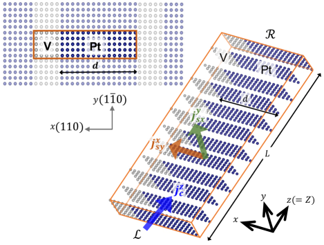
Method.—A fully relativistic quantum mechanical scattering scheme was used to study transport in the thermally disordered, [110]-oriented, thin Pt film sketched in Fig. 1. The disordered Pt film is sandwiched between left () and right () Pt leads in the and directions. In the first step of a two-stage procedure, Bloch eigenstates at the Fermi energy of the crystalline Pt leads are determined and classified according to whether they propagate in the or direction. In the second step, these scattering states are used as boundary conditions to find quantum mechanical solutions throughout the scattering region using Ando’s wave-function matching scheme [19] implemented [20, *Starikov:prb18] using a very efficient basis of tight-binding muffin tin orbitals [22, *Andersen:85, *Andersen:prb86]. Periodic boundary conditions are used in the and directions whereby use can be made of Bloch’s theorem to efficiently determine and keep track of the lead states [25]. The resulting periodic images of the thin film are separated by vacuum that is represented in the atomic spheres approximation (ASA) using “empty spheres” [26, *Skriver:prb92b, 28]. For the density functional theory calculations, we used the local spin density approximation as parameterised by von Barth and Hedin (vBH) [29], the experimental lattice constant, an basis and omit three-centre terms in the SOC matrix. The potential calculation was iterated to self consistency with SOC included [30, 31].
A charge current is passed through the thin diffusive Pt film in the direction by applying an infinitesimal voltage difference between the Pt leads so that at the Fermi energy only Bloch states propagating in the direction are occupied in the lead and Bloch states propagating in the direction are unoccupied in the lead. From the results of the scattering calculations, spin currents in the and directions are calculated as in Ref. [16]; their interpolation onto a three dimensional grid is described in Ref. [32].
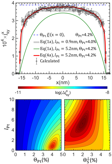
Calculations.—The results we find for the spin Hall current flowing towards the surface of the thin film sketched in Fig. 1 are presented in Fig. 2 for a free standing Pt slab of thickness nm corresponding to 115 atomic layers in the direction that are separated from their periodic images by five layers of empty spheres. 90 layers of this 360=(115+5) supercell were stacked in the direction and the atoms in the scattering region were displaced at random with a Gaussian distribution of atomic displacements chosen to reproduce the experimental bulk resistivity of cm [33, *LiuY:prb15, 35] at room temperature (RT=). The thickness of the slab is for a value of nm estimated from the decay of a fully polarized spin current injected into Pt [16, 18] making it essentially bulk-like. Consistent with this is that at the center of the slab, the spin Hall angle (the ratio of the transverse spin current measured in units of to the longitudinal charge current measured in units of the electron charge ) is the bulk value, [16]. Small oscillations that are discernible in the calculated profiles are attributable to standing waves that are not described by semi-classical (Boltzmann) descriptions of transport. Using the bulk values of and in (1a) yields the green curve in Fig. 2 that is clearly a poor representation of the ab-initio results. If instead we perform a least squares fit in the parameter space (bottom left panel), we find a best fit with nm and yielding the grey curve in Fig. 2 (top panel). Although we know what and should be from our bulk calculations [16, 18], we are unable to recover these values from the present calculations for a bulk-like thin film carried out with the same approximations. We identify the boundary condition of (1a) and (1b) used to extract and from the spin current as the culprit.
Improved Valet-Fert model.—To understand the discrepancy, we generalize the Valet-Fert (VF) model of Zhang [6] to include surface spin-flipping and a surface SHE. To include surface effects, the thin film geometry is modelled as an SNMS trilayer with surface (S) regions of finite thickness sandwiching the non-magnetic “bulk” metal (NM) of thickness in the direction as shown schematically in Fig. 3(a). For each layer S, NM), the transverse spin current density and spin accumulation excited by a longitudinal charge current density in the direction are
| (2a) | ||||
| (2b) | ||||
where describes the decay of a spin current in the layer , is its resistivity and its spin Hall angle. The metallic layer has inversion symmetry and the spin current and spin accumulation are continuous across the interface. The surface layer is anisotropic and all three transport properties are considered to be tensors with the independent elements . Since we are interested in spin diffusion perpendicular to the surface, and do not enter (2) while is implicit in . We are left with three parameters and governing transport perpendicular to the surface in the finite surface layer that cannot be determined by fitting equations (2) for and . Instead, taking the limit leads to the surface areal resistance and spin-memory loss (SML) parameter defined as
| (3) |
where describes the spin current discontinuity that arises when and the prefactor of the first term on the right-hand side of (2a) becomes . Since there is no transport across the surface into the vacuum, we set so the first term in (2a) vanishes giving rise to the boundary condition compared to in (1a). We use this condition and inversion symmetry in the direction to eliminate the coefficients and for the slab.
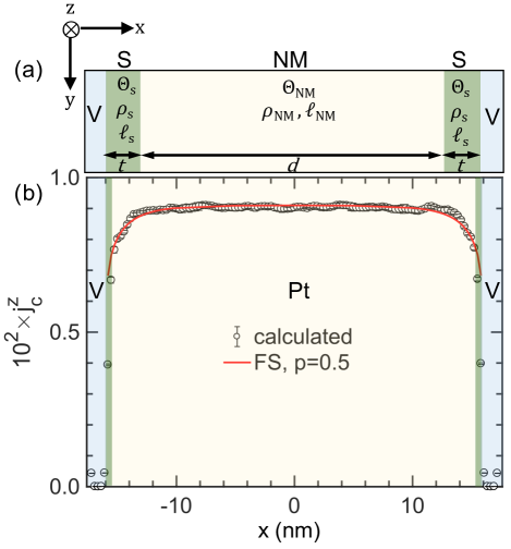
Introducing a surface region whose transport properties differ from those of the bulk poses the question as to how the longitudinal charge transport is affected by the surface. In Fig. 3(b), is seen to deviate in the topmost 10 atomic layers from a constant bulk value and can be fit essentially perfectly using the Fuchs-Sondheimer (FS) theory [36, 37] with the RT bulk resistivity , the mean-free-path nm estimated in the relaxation time approximation with the Fermi velocity averaged over the Fermi surface [18], and a specularity coefficient , without needing to explicitly invoke the surface transport parameter . Using this as the longitudinal charge current driving the spin-Hall current in (2a), we arrive at the following expressions describing spin diffusion in the presence of the spin Hall effect in a thin film
| (4a) | ||||
| (4b) | ||||
where the coefficient
| (5) |
is clearly a surface dependent quantity and
| (6) |
For the [110] surface we find a value of , substantially lower than the bulk value. This result as well as those for [001] and [111] oriented films are given in Table 1. For the very smooth [111] surface we also considered a “rough” variant prepared by randomly removing half of the atoms from the topmost layer. The results obtained from (6) are seen to exhibit a very strong dependence on the surface orientation. This comes about not because of a strong dependence of on the surface but because of (i) the FS suppression of close to the surface and (ii) the connectivity of the atoms making up the surface layer that affects greatly. For example, has a large value for the smooth [111] surface where every surface atom has six neighbouring surface atoms. It is this which leads to a relatively large value of and low value of .
| Clean | Rough | ||||
|---|---|---|---|---|---|
| [110] | [100] | [111] | [111] | ||
| 0.5 | 0.5 | 0.4 | 0.2 | ||
| (%) | Eq.(6) | 2.0 | 1.7 | 0.1 | 3.1 |
| Eqs.(4a)&(5) | 2.1 | 3.8 | 3.5 | 2.0 | |
| (%) | 8.8 | 7.0 | 7.7 | 6.3 | |
Just as the resistivity is not a local property on the length scale of the mean free path, there is no reason to describe the SHE as a local property as is done by the semiclassical VF description. At the centre of the thin film furthest from the surfaces, the absolute value of the leading, diffusive term in (4a) has its minimum value and as indicated by the dashed blue reference line in Fig. 2 corresponding to the bulk value of [16]. Fixing at this bulk value, we scan the parameter space with (4a) and find a minimum occurs for values of in the range 4–6 nm and of in the range 1.8–2.2%, Fig. 2 (bottom right). Alternatively, we can fix and at their bulk values nm} and optimize the fit of (4a) and (5) to the ab-initio values of using the remaining free parameter . The result of doing so for the [110] surface is the red curve in Fig. 2 for a value of . The fit is seen to be excellent. Values of obtained for the other surfaces in this way are given in Table 1 where a suppression of the surface SHA is seen for all orientations.
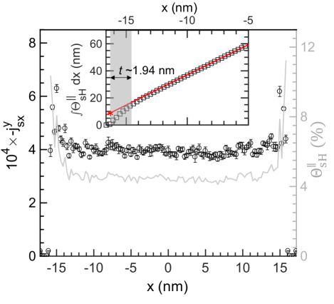
Surface enhancement of .—We have seen that and depend strongly on the distance to a surface in a thin film. In Fig. 4 we plot the spin current that flows parallel to the surface, , and see that it also depends quite strongly on . Unlike that changes on a length scale of , is essentially constant up to a mean-free-path of the surface where it increases to reach of its mean value at the centre of the slab in spite of the FS suppression of the driving charge current shown in Fig. 3. Thus in a sample that is finite in the and directions, see Fig. 1, a spin Hall current diffusing towards a surface or an interface will have an additional contribution from the surfaces parallel to the direction of diffusion.
To extract a surface SHA, we integrate from a position in the vacuum where all currents vanish, through the surface at , in to and plot the result as a function of in the inset to Fig. 4. Using a linear fit we identify a surface region of thickness nm between where the integrated curve deviates from the linear bulk contribution and where it vanishes. We define the ratio of the corresponding intercept on the axis (red asterisk in Fig. 4) to as the surface contribution . For the [110] thin film, this ratio yields . Results for the other orientations given in Table 1 are all enhanced compared to the bulk value of .
Discussion.—To understand the lateral spin current profile in a thin film, allowance must be made for a variation of the SHA at the surface [39] as well as the Fuchs-Sondheimer suppression of the driving charge current density. When this is done, the spin-current profile that we calculate from first-principles scattering theory is consistent with bulk values of the SHA and SDL that we calculated using the same methodology [16, 18]. No evidence is found for a recently reported value of nm obtained from MOKE observations of the spin accumulation induced in thin films by the SHE [17]. The asymptotic “bulk” resistivity of 20.6cm that Stamm et al. report for thick films [17] is twice the handbook value quoted for RT Pt [35]. Although polycrystallinity and grain boundary scattering are frequently invoked [40, 41] to account for the increased resistivity of thin films [42, 43, 44, 45, 46] and wires [47, 48, 45], it is not known what effect these might have on the SHE-induced spin accumulation nor is any structural characterization reported that might account for the increased resistivity [17]. From the Elliott-Yafet relation const., one might expect to be shorter when the resistivity is high rather than longer.
Summary.—First-principles calculations are used to examine the diffusion of the intrinsic spin Hall current perpendicular to the surface of a thin film of Pt at room temperature when a charge current is passed through the thin film. A marked suppression of the charge current parallel to the surface is found to be well reproduced by a phenomenological model due to Fuchs and Sondheimer and leads to a reduction of the spin-current source. A model of spin diffusion that is widely used to interpret experimental SHE studies fails to reproduce the spin current profiles that we calculate leading us to develop a more general model that provides an accurate description of the calculated spin current. A substantial enhancement of the spin Hall current parallel to the surface is predicted.
Acknowledgments.—This work was financially supported by the “Nederlandse Organisatie voor Wetenschappelijk Onderzoek” (NWO) through the research programme of the former “Stichting voor Fundamenteel Onderzoek der Materie,” (NWO-I, formerly FOM) and through the use of supercomputer facilities of NWO “Exacte Wetenschappen” (Physical Sciences). R.S.N. acknowledges funding from the Shell-NWO/FOM “Computational Sciences for Energy Research” PhD program (CSER project number 15CSER12).
References
- D’yakonov and Perel [1971] M. I. D’yakonov and V. I. Perel, Possibility of orienting electron spins with current, Zh. Eksp. Teor. Fiz. 13, 657 (1971), [JETP Letters-USSR 13, pp 467-469 (1971)].
- Dyakonov and Perel [1971] M. I. Dyakonov and V. I. Perel, Current-induced spin orientation of electrons in semiconductors, Phys. Lett. A 35, 459 (1971).
- Hirsch [1999] J. E. Hirsch, Spin Hall Effect, Phys. Rev. Lett. 83, 1834 (1999).
- Hoffmann [2013] A. Hoffmann, Spin Hall effects in metals, IEEE Trans. Magn. 49, 5172 (2013).
- Sinova et al. [2015] J. Sinova, S. O. Valenzuela, J. Wunderlich, C. H. Back, and T. Jungwirth, Spin Hall effects, Rev. Mod. Phys. 87, 1213 (2015).
- Zhang [2000] S. Zhang, Spin Hall Effect in the Presence of Spin Diffusion, Phys. Rev. Lett. 85, 393 (2000).
- Valet and Fert [1993] T. Valet and A. Fert, Theory of the perpendicular magnetoresistance in magnetic multilayers, Phys. Rev. B 48, 7099 (1993).
- Saitoh et al. [2006] E. Saitoh, M. Ueda, H. Miyajima, and G. Tatara, Conversion of spin current into charge current at room temperature: Inverse spin-Hall effect, Appl. Phys. Lett. 88, 182509 (2006).
- Ando et al. [2008] K. Ando, S. Takahashi, K. Harii, K. Sasage, J. Ieda, S. Maekawa, and E. Saitoh, Electric Manipulation of Spin Relaxation Using the Spin Hall Effect, Phys. Rev. Lett. 101, 036601 (2008).
- Mosendz et al. [2010] O. Mosendz, J. E. Pearson, F. Y. Fradin, G. E. W. Bauer, S. D. Bader, and A. Hoffmann, Quantifying Spin Hall Angles from Spin Pumping: Experiments and Theory, Phys. Rev. Lett. 104, 046601 (2010).
- Liu et al. [2011a] L. Liu, T. Moriyama, D. C. Ralph, and R. A. Buhrman, Spin-Torque Ferromagnetic Resonance Induced by the Spin Hall Effect, Phys. Rev. Lett. 106, 036601 (2011a).
- Kimura et al. [2007] T. Kimura, Y. Otani, T. Sato, S. Takahashi, and S. Maekawa, Room-Temperature Reversible Spin Hall Effect, Phys. Rev. Lett. 98, 156601 (2007).
- Vila et al. [2007] L. Vila, T. Kimura, and Y. C. Otani, Evolution of the Spin Hall Effect in Pt Nanowires: Size and Temperature Effects, Phys. Rev. Lett. 99, 226604 (2007).
- Bass and Pratt Jr. [2007] J. Bass and W. P. Pratt Jr., Spin-diffusion lengths in metals and alloys, and spin-flipping at metal/metal interfaces: an experimentalist’s critical review, J. Phys.: Condens. Matter 19, 183201 (2007).
- Rojas-Sánchez et al. [2014] J.-C. Rojas-Sánchez, N. Reyren, P. Laczkowski, W. Savero, J.-P. Attané, C. Deranlot, M. Jamet, J.-M. George, L. Vila, and H. Jaffrès, Spin Pumping and Inverse Spin Hall Effect in Platinum: The Essential Role of Spin-Memory Loss at Metallic Interfaces, Phys. Rev. Lett. 112, 106602 (2014).
- Wesselink et al. [2019] R. J. H. Wesselink, K. Gupta, Z. Yuan, and P. J. Kelly, Calculating spin transport properties from first principles: spin currents, Phys. Rev. B 99, 144409 (2019).
- Stamm et al. [2017] C. Stamm, C. Murer, M. Berritta, J. Feng, M. Gabureac, P. M. Oppeneer, and P. Gambardella, Magneto-Optical Detection of the Spin Hall Effect in Pt and W Thin Films, Phys. Rev. Lett. 119, 087203 (2017).
- Nair et al. [2021] R. S. Nair, E. Barati, K. Gupta, Z. Yuan, and P. J. Kelly, Spin-Flip Diffusion Length in 5 Transition Metal Elements: a First-Principles Benchmark, Phys. Rev. Lett. 126, 196601 (2021).
- Ando [1991] T. Ando, Quantum point contacts in magnetic fields, Phys. Rev. B 44, 8017 (1991).
- Starikov et al. [2010] A. A. Starikov, P. J. Kelly, A. Brataas, Y. Tserkovnyak, and G. E. W. Bauer, Unified First-Principles Study of Gilbert Damping, Spin-Flip Diffusion and Resistivity in Transition Metal Alloys, Phys. Rev. Lett. 105, 236601 (2010).
- Starikov et al. [2018] A. A. Starikov, Y. Liu, Z. Yuan, and P. J. Kelly, Calculating the transport properties of magnetic materials from first-principles including thermal and alloy disorder, non-collinearity and spin-orbit coupling, Phys. Rev. B 97, 214415 (2018).
- Andersen and Jepsen [1984] O. K. Andersen and O. Jepsen, Explicit, First-Principles Tight-Binding Theory, Phys. Rev. Lett. 53, 2571 (1984).
- Andersen et al. [1985] O. K. Andersen, O. Jepsen, and D. Glötzel, Canonical description of the band structures of metals, in Highlights of Condensed Matter Theory, International School of Physics ‘Enrico Fermi’, Varenna, Italy, edited by F. Bassani, F. Fumi, and M. P. Tosi (North-Holland, Amsterdam, 1985) pp. 59–176.
- Andersen et al. [1986] O. K. Andersen, Z. Pawlowska, and O. Jepsen, Illustration of the linear-muffin-tin-orbital tight-binding representation: Compact orbitals and charge density in Si, Phys. Rev. B 34, 5253 (1986).
- Xia et al. [2006] K. Xia, M. Zwierzycki, M. Talanana, P. J. Kelly, and G. E. W. Bauer, First-principles scattering matrices for spin-transport, Phys. Rev. B 73, 064420 (2006).
- Skriver and Rosengaard [1992a] H. L. Skriver and N. M. Rosengaard, Ab initio work function of elemental metals, Phys. Rev. B 45, 9410 (1992a).
- Skriver and Rosengaard [1992b] H. L. Skriver and N. M. Rosengaard, Surface energy and work function of elemental metals, Phys. Rev. B 46, 7157 (1992b).
- Daalderop et al. [1994] G. H. O. Daalderop, P. J. Kelly, and M. F. H. Schuurmans, Magnetic anisotropy of a free-standing Co monolayer and of multilayers which contain Co monolayers, Phys. Rev. B 50, 9989 (1994).
- von Barth and Hedin [1972] U. von Barth and L. Hedin, A local exchange-correlation potential for the spin-polarized case: I, J. Phys. C: Sol. State Phys. 5, 1629 (1972).
- foo [a] We use Mark van Schilfgaarde’s “lm” extension of the Stuttgart LMTO code that treats non-collinear magnetization and spin-orbit coupling and is maintained in the questaal suite at https://www.questaal.org.
- foo [b] With these parameters, we obtain bulk values of nm and ; see Table IV of reference [16]. If instead of the vBH exchange correlation potential we use the PBE generalised gradient approximation [49], we obtain values of nm and .
- Nair and Kelly [2021] R. S. Nair and P. J. Kelly, Fully resolved currents from quantum transport calculations, Phys. Rev. B 103, 195406 (2021).
- Liu et al. [2011b] Y. Liu, A. A. Starikov, Z. Yuan, and P. J. Kelly, First-principles calculations of magnetization relaxation in pure Fe, Co, and Ni with frozen thermal lattice disorder, Phys. Rev. B 84, 014412 (2011b).
- Liu et al. [2015] Y. Liu, Z. Yuan, R. J. H. Wesselink, A. A. Starikov, M. van Schilfgaarde, and P. J. Kelly, Direct method for calculating temperature-dependent transport properties, Phys. Rev. B 91, 220405(R) (2015).
- Lide [2009] D. R. Lide, ed., CRC Handbook of Chemistry and Physics, 90th Edition (Internet Version 2010) (CRC Press/Taylor and Francis, Boca Raton, FL, 2009).
- Fuchs [1938] K. Fuchs, The conductivity of thin metallic films according to the electron theory of metals, Proc. Camb. Phil. Soc. 34, 100 (1938).
- Sondheimer [1952] E. H. Sondheimer, The mean free path of electrons in metals, Adv. Phys. 1, 1 (1952).
- Lucas [1965] M. S. P. Lucas, Electrical conductivity of thin metallic films with unlike surfaces, J. Appl. Phys. 36, 1632 (1965).
- Wang et al. [2016] L. Wang, R. J. H. Wesselink, Y. Liu, Z. Yuan, K. Xia, and P. J. Kelly, Giant Room Temperature Interface Spin Hall and Inverse Spin Hall Effects, Phys. Rev. Lett. 116, 196602 (2016).
- Mayadas et al. [1969] A. F. Mayadas, M. Shatzkes, and J. F. Janak, Electrical resistivity model for polycrystalline films - case of specular reflection at external surfaces, Appl. Phys. Lett. 14, 345 (1969).
- Mayadas and Shatzkes [1970] A. F. Mayadas and M. Shatzkes, Electrical-resistivity model for polycrystalline films: the case of arbitrary reflection at external surfaces, Phys. Rev. B 1, 1382 (1970).
- de Vries [1988] J. W. C. de Vries, Temperature and thickness dependence of the resistivity of thin polycrystalline aluminium, cobalt, nickel, palladium, silver and gold films, Thin Solid Films 167, 25 (1988).
- Wu et al. [2004] W. Wu, S. H. Brongersma, M. Van Hove, and K. Maex, Influence of surface and grain-boundary scattering on the resistivity of copper in reduced dimensions, Appl. Phys. Lett. 84, 2838 (2004).
- Chawla and Gall [2009] J. S. Chawla and D. Gall, Specular electron scattering at single-crystal Cu(001) surfaces, Appl. Phys. Lett. 94, 252101 (2009).
- Chawla et al. [2011] J. S. Chawla, F. Gstrein, K. P. O’Brien, J. S. Clarke, and D. Gall, Electron scattering at surfaces and grain boundaries in Cu thin films and wires, Phys. Rev. B 84, 235423 (2011).
- Dutta et al. [2017] S. Dutta, K. Sankaran, K. Moors, G. Pourtois, S. Van Elshocht, J. Bömmels, W. Vandervorst, Z. Tőkei, and C. Adelmann, Thickness dependence of the resistivity of platinum-group metal thin films, J. Appl. Phys. 122, 025107 (2017).
- Steinhögl et al. [2002] W. Steinhögl, G. Schindler, G. Steinlesberger, and M. Engelhardt, Size-dependent resistivity of metallic wires in the mesoscopic range, Phys. Rev. B 66, 075414 (2002).
- Josell et al. [2009] D. Josell, S. H. Brongersma, and Z. Tőkei, Size-dependent resistivity in nanoscale interconnects, Ann. Rev. Mat. Res. 39, 231 (2009).
- Perdew et al. [1996] J. P. Perdew, K. Burke, and M. Ernzerhof, Generalized gradient approximation made simple, Phys. Rev. Lett. 77, 3865 (1996).