Dirac fermions in half-metallic ferromagnetic mixed CrMxPSe3 monolayers
Abstract
The electronic and magnetic properties of pristine CrPSe3 and mixed CrMxPSe3 (M = Zn, Cd, Hg) monolayers were studied using density functional theory including an on-site Coulomb term (DFT) and tight-binding approach (TBA). While pristine CrPSe3 monolayer has an antiferromagnetic (AFM) ground state, its alloying with MPSe3 may give rise to half-metallic ferromagnet (HMF) with high Curie temperature. The resulting monolayers demonstrate single-spin Dirac cones of mainly Cr- character located in the first Brillouin zone directly at the Fermi energy. The calculated Fermi velocities of Dirac fermions indicate very high mobility in mixed CrMxPSe3 monolayers, that makes this material appealing for low-dimensional spintronics applications.
Discovery of the fascinating transport properties of graphene Novoselov et al. (2005); Zhang et al. (2005); Geim and Novoselov (2007) stimulated the enormous interest to the family of two-dimensional (2D) materials, leading to the success in the synthesis or exfoliation from bulk of different 2D materials, like -BN Oshima and Nagashima (1997); Tonkikh et al. (2016); Zhang et al. (2017), black phosphorene Carvalho et al. (2016), silicene Houssa et al. (2015); Molle et al. (2018), transition-metal dichalcogenides Dong and Kuljanishvili (2017); Manzeli et al. (2017) and many others. Here, the electronic structure is ranged from metallic (graphene, silicene) to insulating (-BN) state. Although a great quantity of 2D crystals have been widely explored, most of them are lacking of intrinsic ferromagnetic (FM) ordering. Inspired by the discovery of layer-dependent ferromagnetism in insulating CrI3 monolayer with a Curie temperature () of K Huang et al. (2017), many 2D magnetic materials have been recently synthesized, such as semiconducting Cr2Ge2Te6 Gong et al. (2017), its metallic analogue Fe3GeTe2 Deng et al. (2018), and semiconducting MnSe2 O’Hara et al. (2018), initiating enormous attention to the field of magnetic 2D atomic crystals Burch et al. (2018); Gibertini et al. (2019). Meanwhile, some novel properties have been also predicted for the 2D magnetic materials, e. g. the Dirac spin-gapless semiconductor state for NiCl3 and -V2O3 monolayers He et al. (2017); Gog et al. (2019), topological magnetic-spin textures in Cr2Ge2Te6 Han et al. (2019), spontaneous valley splitting in 2D VAgP2Se6 Song et al. (2018), etc. Thus, the rapidly advancing progress in the field of the studies of magnetism in pure 2D materials offers great opportunities for new physical paradigms and next generation information technology Burch et al. (2018).
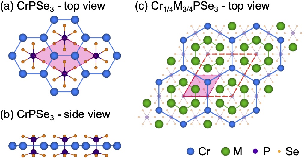
Currently, increased research attention is focused on transition-metal phosphorus trichalcogenides (MPX3 with M = transition metal and X = S, Se), which crystals can be easily exfoliated into monolayers Du et al. (2016), where a single 2D unit consisting of the transition metal atoms shows honeycomb lattice structure similar to that of graphene (Fig. 1a,b). However, unlike graphene, which has a zero band gap, members of the MPX3 family demonstrate wide variation of band gaps ranging from eV to eV Wang et al. (2018). In addition, transition metal compounds have a large spin-orbit coupling and strong electronic correlations compared to the case of graphene.
Overall, due to the diversity of fully or partially occupied -orbitals for the transition metal ions, one may expect a variety of magnetic behavior for MPX3 monolayers. In this regard, 2D monolayers were studied mostly by theoretical methods, excepting the case of M = Fe for which experimental results are available as well Lee et al. (2016). According to the recent theoretical studies, most of 2D MPX3 monolayers have antiferromagnetic (AFM) arrangement of magnetic moments of transition metal ions in their ground states Chittari et al. (2016); Sivadas et al. (2015); Kim et al. (2018); Yang et al. (2020).
The magnetic phase transition for the MPX3 materials to the FM state can be realized through applying stress Chittari et al. (2016) or modulating the carrier concentration Li et al. (2014). For instance, it was theoretically shown that by means of applying an external voltage gate 2D MnPX3 (X = S, Se) can be converted from the AFM semiconducting state into the half-metallic ferromagnetic (HMF) state with K Li et al. (2014). A further approach to alter the magnetic properties is alloying. Here the properties can be tailored with variation of the concentration of an alloying extent Masubuchi et al. (2008); Goossens et al. (2013).
In this manuscript, the electronic and magnetic properties of 2D CrPSe3 monolayers are studied using density functional theory including an on-site Coulomb term (DFT) and tight-binding approach (TBA). While CrPSe3 demonstrates the AFM ground state, its alloying with MPSe3 (M = Zn, Cd, Hg) can be used to stabilize the FM state. CrMxPSe3 () is the HMF (Dirac spin-gapless semiconducting) state with near room temperature , obtained in the Monte Carlo simulations. This HMF state emerges Dirac cones in the first 2D Brillouin zone, which originate from the long-range exchange interactions between the -orbitals of Cr2+ ions formed a honeycomb lattice. If spin-orbit coupling (SOC) is taken into account, the CrMxPSe3 monolayers become an intrinsic Chern insulators with a large non-trivial band gaps. The high Curie temperature and single-spin Dirac states with high Fermi velocities make 2D CrMxPSe3 monolayers very promising materials for low-dimensional spintronics applications.
| System | MAE | ||||||
|---|---|---|---|---|---|---|---|
| CrPSe3 | ()b; | – | |||||
| Cr1/4Zn3/4PSe3 | ()b; | ||||||
| Cr1/4Cd3/4PSe3 | ()b; | ||||||
| Cr1/4Hg3/4PSe3 | ()b; |
aat K and K/2, respectively; bfor the data in parenthesis SOC is taken into account
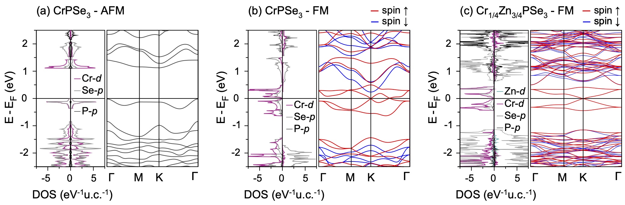
Our DFT calculations (see Supplemental Material Sup for computational details) show that 2D CrPSe3 crystal prefers the AFM coupling in its ground state with K (see Tab. S1, Fig. S1, and Fig. S2 in Supplemental Material Sup ). The high-spin configuration of Cr2+ results in . The calculated electronic band structure indicates that the 2D CrPSe3 crystal is a semiconductor with an indirect band gap of eV (Fig. 2a). Due to the quantum confinement effects this value is slightly larger than the recently published band gap value of a bulk phase ( eV) Dedkov et al. (2020). The bands in the vicinity of Fermi energy are mostly composed of Cr- and Se- orbitals. Hence, the – exchange interactions are much weaker than the direct – exchange interactions between the NN Cr ions with a bond Å, leading to the high negative value of meV (see Supplementary Material Sup for additional theoretical details). For the 2NN and 3NN Cr-ions, the direct – interactions decrease significantly with increasing distance between Cr-ions and considerable long-range – super-exchange interactions result in positive values of meV and meV. Thus, the origin of the AFM ground-state can be attributed to the competition between the NN AFM direct Cr–Cr (–) exchange interactions and the indirect Cr–SeSe–Cr (–) superexchange interactions.
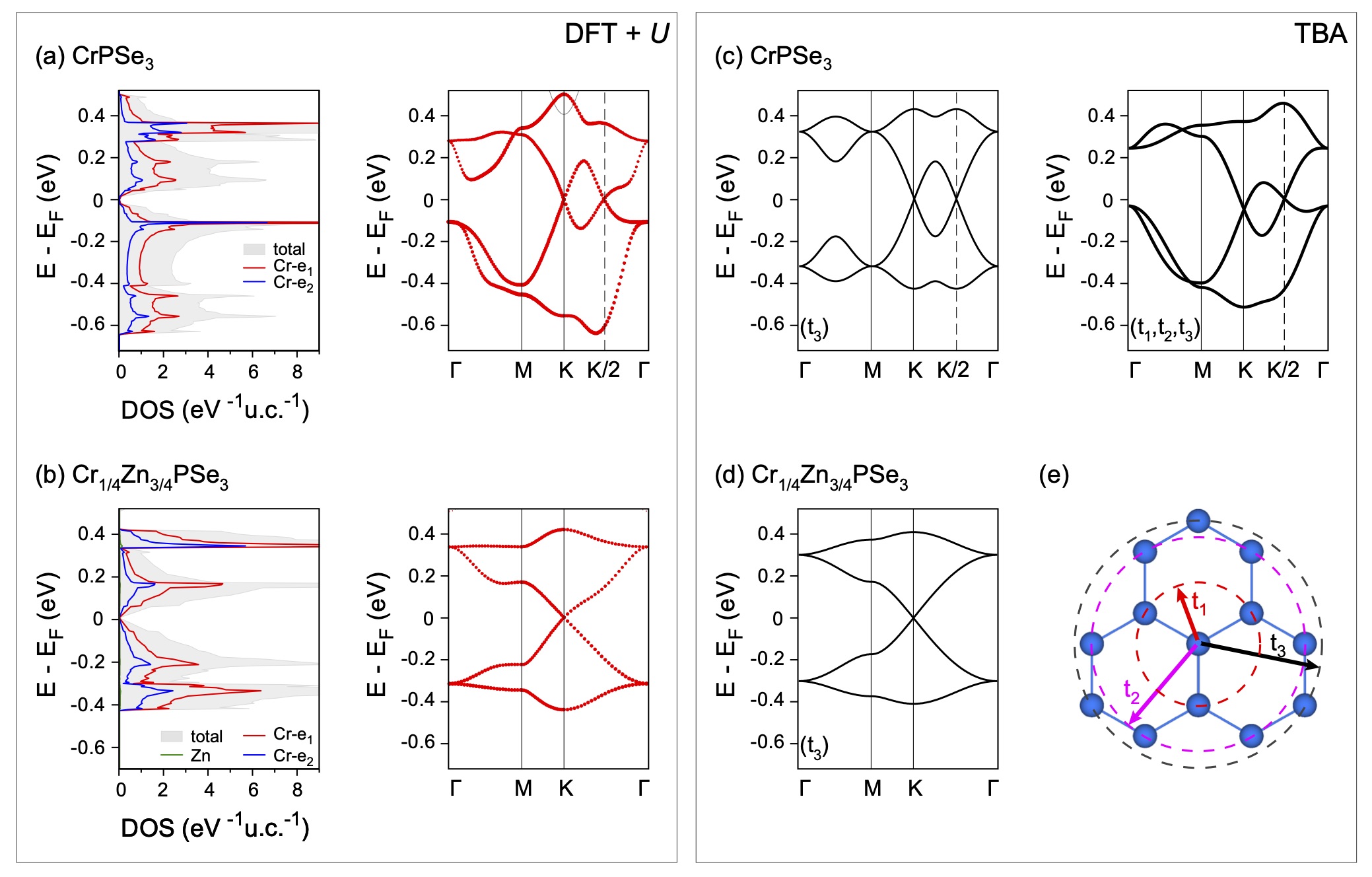
The FM state of 2D CrPSe3 is meV higher in energy than the AFM ground-state (Tab. 1). Still, it attracts our attention due to its exciting band structure, which demonstrates a half-metallic state with the metallic spin-up channel and insulating spin-down channel (Fig. 2b). For the spin-up electrons, the linear dispersion is observed in the vicinity of the Fermi level and multiple cones appear: one at the K point and an extra one around the midpoint of the – K line named as K/2. The spin-up states near the Fermi level are dominated by Cr- and Cr- orbitals (Fig. 3a), which are hybridized with the orbitals of Se. The calculations with SOC included lead to the gap opening of meV and meV for spin-up states at the K and K/2 points, respectively (see Supplemental Material Sup Fig. S3a for the calculated band structures).
In order to better understand the observed phenomena a TBA was applied to the studied system (see Supplementary Material Sup for additional theoretical details). Here the and orbitals can be used as a basis for the honeycomb lattice formed by Cr2+ ions and the hopping parameters (NN), (2NN), and (3NN) are marked in Fig. 3e for this lattice. The modelled band structures are presented in Fig. 3c and they are in reasonable agreement with DFT-calculated band structure (Fig. 3a). Interestingly, the Dirac cones are accurately located at the K point and K/2 midpoint with vertexes just crossed by the Fermi level when considering only the 3NN hopping elements. From a comparison between the two different TBA band structures, the and interactions were found to introduce hole pockets at the K/2 point and electron pockets at the K point, respectively. Since the lattice sites connected by 3NN bonds also form a honeycomb structure with a twice larger lattice constant, the Dirac cones at the K points are folded to the midpoints along the – K path. The TBA results confirm that the robust Dirac cones are strongly protected by the lattice symmetry, especially, by the mirror symmetry along the – K path. Thus, the origin of the observed Dirac cones can be attributed to the honeycomb lattice structure composed from chromium ions.
In the next step we intend to find a way for stabilisation of the FM state in CrPSe3. Here we propose to use its alloying with MPSe3 with M = group-12 metals. The 2D ZnPSe3, CdPSe3, and HgPSe3 are paramagnetic compounds, which correlates with the -configuration of Zn, Cd, and Hg. They are semiconductors with the calculated indirect gaps of eV, eV, eV, respectively (see Tab. S2 in Supplemental Material Sup ). These DFT values are underestimated with respect to the available experimental data ( eV Calareso et al. (1997a), eV Calareso et al. (1997b)), but in agreement with the previously published theoretical results Xiang et al. (2016). The band edges of these monolayers are composed from Se- orbitals, whereas the completely filled -states are strongly localized at around eV below the Fermi level (see Fig. S4 in Supplemental Material Sup ).
As shown above, the origin of the AFM ground-state of 2D CrPSe3 can be attributed to the competition between the NN AFM direct Cr–Cr (–) exchange interactions and the indirect Cr–SeSe–Cr (–) superexchange interactions. Consequently, FM may arise when the direct – coupling is significantly weakened or even entirely absent. This can be achieved if all nearest-neighbour Cr ions will be substituted by group-12 metal ions, i. e. by means of alloying of CrPSe3 and MPX3 with the ratio Cr : M = 1 : 3. The proposed structure for such an alloy is presented in Fig. 1c.
In order to check our idea, we performed the electronic structure calculations for the suggested alloy, i. e. Cr1/4M3/4PSe3. As expected, all systems under study prefer the FM ground states (Tab. 1). In order to further confirm our idea, we carried out similar calculations for the opposite case, i. e. Cr3/4M1/4PSe3, and observed stabilisation of the AFM coupling (see Fig. S5 and Tab. S4 in Supplemental Material Sup ). The spin-resolved band structure of Cr1/4Zn3/4PSe3 in the ground-state configurations is presented in Fig. 2c. The band structures for the cases of M = Cd and Hg show similar behavior and can be seen in Supplemental Material Sup (Fig. S5). All systems under consideration show the HFM behavior with the metallic spin-up channel and insulating spin-down one. The Dirac fermions emerge at the high-symmetry K point in the vicinity of the Fermi level. These Dirac cones are spin-polarized and resulted from the strong hybridization between Cr- and Se- orbitals. The Cr–Cr interactions are still strong enough in these systems, despite of a long length larger than Å for the Cr-honeycomb lattices. Still the FM – superexchange interactions prevail resulting in large (3NN Cr–Cr pair) values of meV, meV, and meV, obtained for Cr1/4M3/4PSe3 with M = Zn, Cd, and Hg, respectively (Tab. 1). Using the calculated exchange parameters we have employed Monte-Carlo simulations based on the Ising model and estimated Curie temperatures () (see Supplementary Material Sup , Fig. S6). The calculated listed in Tab. 1 suggest the possibility of using the studied monolayers in near-room temperature spintronics.
The electronic structure of Cr1/4Zn3/4PSe3 shows rather rare Dirac spin-gapless semiconductor characteristics that are essential for potential high-speed spin filter devices. The calculated Fermi velocities () in the – K direction for Dirac electrons at the Fermi level are: , , and for Cr1/4M3/4PSe3 with M = Zn, Cd, and Hg, respectively. These values for are about a half of the graphene value of Malko et al. (2012), demonstrating the excellent electronic transport properties of Cr1/4M3/4PSe3 monolayers. Since the Dirac electrons are derived from the strong – hybridization, the SOC effect was considered to open a band gap. The SOC-induced estimated gaps are meV, meV and meV for Cr1/4M3/4PSe3 with M = Zn, Cd, and Hg, respectively (see Supplementary Material Sup , Fig. S3b-d). These gaps are significantly larger than that of the other Dirac materials, such as graphene Gmitra et al. (2009); Abdelouahed et al. (2010), which are characterized by Dirac states composed of -orbitals with weak spin-orbital couplings.
As for pristine CrPSe3, TBA with and orbitals used as a basis for the honeycomb lattice formed by Cr2+ ions was applied for the systems under study (see Tab. S3 in Supplementary Material Sup ). The band structure obtained for M = Zn is presented in Fig. 3d and it is in a good agreement with DFT-calculated band structure (Fig. 3b). Especially the Dirac cone at the K point as well as the bandwidth calculated with TBA are well reproduced. The hopping parameter controls the band width while affects the band dispersion, respectively. Some differences between TBA and DFT band structures are caused by the neglecting of the contributions from Se orbitals.
In conclusion, the electronic structure of 2D CrPSe3 monolayer was explored using first-principles calculations. The calculated band structures obtained on the DFT level illustrate that the 2D CrPX3 monolayers adopt the AFM ground state. Simultaneously, its FM state is half-metallic ferromagnet with multiple spin-polarized Dirac cones. Deep analysis of the observed phenomenon allowed us to find the way to stabilize the FM state by means of alloying of the studied system with MPSe3, where M is group-12 metal (Zn, Cd, Hg). Depending on the concentration and location of the alloying extend, it is possible to achieve the HMF Dirac spin-gapless semiconducting state in the FM phase for CrMxPSe3 () monolayers. For such cases, the Dirac cone is located at the K point of the Brillouin zone and these fully spin-polarized Dirac cones originate from the long-range exchange interactions between the -orbitals of Cr2+ ions formed a honeycomb lattice. Consequently, SOC opens sizable energy gaps for fully spin-polarized Dirac cones, which are significantly larger compared to the case of Dirac states composed of -orbitals. The estimated rather high Curie temperatures, large SOC gaps, high Fermi velocities, and single-spin Dirac states for CrMxPSe3 () monolayers give rise to great expectations for its potential applications in spintronics.
This work was supported by the National Natural Science Foundation of China (Grant No. 21973059). J.Y. was supported by the Natural Science Foundation of Hubei Province (Grant No. 2018CFB724) and of Education Department (Grant No. D20171803).
References
- Novoselov et al. (2005) K. S. Novoselov, A. K. Geim, S. V. Morozov, D. Jiang, M. I. Katsnelson, I. V. Grigorieva, S. V. Dubonos, and A. A. Firsov, Nature 438, 197 (2005).
- Zhang et al. (2005) Y. Zhang, Y.-W. Tan, H. L. Stormer, and P. Kim, Nature 438, 201 (2005).
- Geim and Novoselov (2007) A. K. Geim and K. S. Novoselov, Nat. Mater. 6, 183 (2007).
- Oshima and Nagashima (1997) C. Oshima and A. Nagashima, J. Phys.: Condens. Matter 9, 1 (1997).
- Tonkikh et al. (2016) A. A. Tonkikh, E. Voloshina, P. Werner, H. Blumtritt, B. Senkovskiy, G. Güntherodt, S. S. P. Parkin, and Y. S. Dedkov, Sci. Rep. 6, 23547 (2016).
- Zhang et al. (2017) K. Zhang, Y. Feng, F. Wang, Z. Yang, and J. Wang, J. Mater. Chem. C 5, 11992 (2017).
- Carvalho et al. (2016) A. Carvalho, M. Wang, X. Zhu, A. S. Rodin, H. Su, and A. H. Castro Neto, Nat. Rev. Mater. 1, 16061 (2016).
- Houssa et al. (2015) M. Houssa, A. Dimoulas, and A. Molle, J. Phys.: Condens. Matter 27, 253002 (2015).
- Molle et al. (2018) A. Molle, C. Grazianetti, L. Tao, D. Taneja, M. H. Alam, and D. Akinwande, Chem. Soc. Rev. 47, 6370 (2018).
- Dong and Kuljanishvili (2017) R. Dong and I. Kuljanishvili, J. Vac. Sci. Technol. 35, 030803 (2017).
- Manzeli et al. (2017) S. Manzeli, D. Ovchinnikov, D. Pasquier, O. V. Yazyev, and A. Kis, Nat. Rev. Mater. 2, 17033 (2017).
- Huang et al. (2017) B. Huang, G. Clark, E. Navarro-Moratalla, D. R. Klein, R. Cheng, K. L. Seyler, D. Zhong, E. Schmidgall, M. A. McGuire, D. H. Cobden, et al., Nature 546, 270 (2017).
- Gong et al. (2017) C. Gong, L. Li, Z. Li, H. Ji, A. Stern, Y. Xia, T. Cao, W. Bao, C. Wang, Y. Wang, et al., Nature 546, 265 (2017).
- Deng et al. (2018) Y. Deng, Y. Yu, Y. Song, J. Zhang, N. Z. Wang, Z. Sun, Y. Yi, Y. Z. Wu, S. Wu, J. Zhu, et al., Nature 563, 94 (2018).
- O’Hara et al. (2018) D. J. O’Hara, T. Zhu, A. H. Trout, A. S. Ahmed, Y. K. Luo, C. H. Lee, M. R. Brenner, S. Rajan, J. A. Gupta, D. W. McComb, et al., Nano Lett. 18, 3125 (2018).
- Burch et al. (2018) K. S. Burch, D. Mandrus, and J.-G. Park, Nature 563, 47 (2018).
- Gibertini et al. (2019) M. Gibertini, M. Koperski, A. F. Morpurgo, and K. S. Novoselov, Nature Nanotechnol. 14, 408 (2019).
- He et al. (2017) J. He, X. Li, P. Lyu, and P. Nachtigall, Nanoscale 9, 2246 (2017).
- Gog et al. (2019) H. Gog, W.-F. Li, C. Fang, R. S. Koster, M. Dijkstra, and M. Huis, NPJ 2D Mater. Appl. 3, 18 (2019).
- Han et al. (2019) M.-G. Han, J. A. Garlow, Y. Liu, H. Zhang, J. Li, D. DiMarzio, M. W. Knight, C. Petrovic, D. Jariwala, and Y. Zhu, Nano Lett. 19, 7859 (2019).
- Song et al. (2018) Z. Song, X. Sun, J. Zheng, F. Pan, Y. Hou, M.-H. Yung, J. Yang, and J. Lu, Nanoscale 10, 13986 (2018).
- Du et al. (2016) K.-z. Du, X.-z. Wang, Y. Liu, P. Hu, M. I. B. Utama, C. K. Gan, Q. Xiong, and C. Kloc, ACS Nano 10, 1738 (2016).
- Wang et al. (2018) F. Wang, T. A. Shifa, P. Yu, P. He, Y. Liu, F. Wang, Z. Wang, X. Zhan, X. Lou, F. Xia, et al., Adv. Funct. Mater. 28, 1802151 (2018).
- Lee et al. (2016) J. U. Lee, S. Lee, J. H. Ryoo, S. Kang, T. Y. Kim, P. Kim, C.-H. Park, J.-G. Park, and H. Cheong, Nano Lett. 16, 7433 (2016).
- Chittari et al. (2016) B. L. Chittari, Y. Park, D. Lee, M. Han, A. H. MacDonald, E. Hwang, and J. Jung, Phys. Rev. B 94, 184428 (2016).
- Sivadas et al. (2015) N. Sivadas, M. W. Daniels, R. H. Swendsen, S. O. P. R. B, and 2015, Phys. Rev. B 91, 235425 (2015).
- Kim et al. (2018) S. Y. Kim, T. Y. Kim, L. J. Sandilands, S. Sinn, M.-C. Lee, J. Son, S. Lee, K.-Y. Choi, W. Kim, B.-G. Park, et al., Phys. Rev. Lett. 120, 136402 (2018).
- Yang et al. (2020) J. Yang, Y. Zhou, Q. Guo, Y. S. Dedkov, and E. Voloshina, RSC Adv. 10, 851 (2020).
- Li et al. (2014) X. Li, X. Wu, and J. Yang, J. Am. Chem. Soc 136, 11065 (2014).
- Masubuchi et al. (2008) T. Masubuchi, H. Hoya, T. Watanabe, Y. Takahashi, S. Ban, N. Ohkubo, K. Takase, and Y. Takano, J. Alloys Compd. 460, 668 (2008).
- Goossens et al. (2013) D. J. Goossens, S. Brazier-Hollins, D. R. James, W. D. Hutchison, and J. R. Hester, J. Magn. Magn. Mater. 334, 82 (2013).
- (32) See Supplemental Material at http://XX for technical details and a complete database of the computational results.
- Dedkov et al. (2020) Y. S. Dedkov, M. Yan, and E. Voloshina, Chem. Phys. Lett. 754, 137627 (2020).
- Calareso et al. (1997a) C. Calareso, V. Grasso, and L. Silipigni, J. Appl. Phys. 82, 6228 (1997a).
- Calareso et al. (1997b) C. Calareso, V. Grasso, F. Neri, and L. Silipigni, J. Phys.: Condens. Matter 9, 4791 (1997b).
- Xiang et al. (2016) H. Xiang, B. Xu, Y. Xia, J. Yin, and Z. Liu, RSC Adv. 6, 89901 (2016).
- Malko et al. (2012) D. Malko, C. Neiss, F. Viñes, and A. Görling, Phys. Rev. Lett. 108, 086804 (2012).
- Gmitra et al. (2009) M. Gmitra, S. Konschuh, C. Ertler, C. Ambrosch-Draxl, and J. Fabian, Phys. Rev. B 80, 235431 (2009).
- Abdelouahed et al. (2010) S. Abdelouahed, A. Ernst, J. Henk, I. V. Maznichenko, and U. Starke, Phys. Rev. B 82, 125424 (2010).
Supplementary material for the manuscript: Dirac fermions in half-metallic ferromagnetic mixed CrMxPSe3 monolayers
Juntao Yang,1,2 Yong Zhou,1 Yuriy Dedkov,1,333E-mail: dedkov@shu.edu.cn and Elena Voloshina1,444E-mail: voloshina@shu.edu.cn
Content:
-
1.
Computational details.
-
2.
Calculation of exchange-coupling parameters: , , .
-
3.
Monte-Carlo simulations.
-
4.
TBA model.
-
5.
Tab. S1: Total energies (, in eV per () unit cell) as well as total energies relative to that of the lowest-energy magnetic configuration (, in meV per unit cell) calculated using the PBE ( eV) approximation for the ferromagnetic (FM), Néel antiferromagnetic (AFM), zigzag antiferromagnetic (zAFM), and stripy antiferromagnetic (sAFM) configurations of single-layer CrPSe3.
-
6.
Tab. S2: Results for the pristine 2D MPSe3 monolayers: Ground state magnetic configuration; optimized lattice parameters: in-plane lattice parameter (), layer thickness (), M–M and M–Se distances ( and , band gap ().
-
7.
Tab. S3: The hopping parameters, onsite energies and band widths for Cr1/4M3/4PSe3 (M = Zn, Cd, Hg).
-
8.
Tab. S4: Results for the 2D Cr1-xMxPSe3 (M = Zn, Cd, Hg, ) monolayers obtained for their ground-state states: (in meV/u.c.) is the energy difference between the FM and AFM states; band gaps, (in eV), are given for the spin-up () and spin-down () channels; (in meV) is the exchange coupling parameter between two local spins; (in ) is Cr magnetic moment; (in K) is a critical temperature.
-
9.
Fig. S1: Four different magnetic configurations of 2D CrPSe3: (a) ferromagnetic (FM), (b) Néel antiferromagnetic (AFM), (c) zigzag antiferromagnetic (zAFM), and (d) stripy antiferromagnetic (sAFM).
-
10.
Fig. S2: The Monte-Carlo simulated specific heat capacity as a function of temperature for 2D CrPSe3.
-
11.
Fig. S3: Comparison of band structures of FM-CrPSe3 as well as mixed Cr1/4M3/4PSe3 monolayers in the vicinity of obtained with DFT and with DFT+SOC.
-
12.
Fig. S4: Band structures of 2D MPSe3 (M = Zn, Cd, Hg).
-
13.
Fig. S5: Band structures and orbital-projected density of states calculated for 2D Cr1-xMxPSe3 (M = Zn, Cd, Hg; ) monolayers in their ground-state configurations.
-
14.
Fig. S6: The Monte-Carlo simulated specific heat capacity as a function of temperature for 2D Cr1/4M3/4PSe3 (M = Zn, Cd, Hg).
1. Computational details
Spin-polarised DFT calculations based on plane-wave basis sets of eV cutoff energy were performed with the Vienna ab initio simulation package (VASP) Kresse and Furthmuller (1996); Kresse and Hafner (1994, 1993). The Perdew-Burke-Ernzerhof (PBE) exchange-correlation functional Perdew et al. (1997) was employed. The electron-ion interaction was described within the projector augmented wave (PAW) method Blöchl (1994) with Cr (, , ), P (, ), and Se (, ) states treated as valence states. The Brillouin-zone integration was performed on -centred symmetry reduced Monkhorst-Pack meshes using a Gaussian smearing with eV, except for the calculation of total energies. For these calculations, the tetrahedron method with Blöchl corrections Blöchl et al. (1994) was employed. A -mesh was used in the case of ionic relaxations and for single point calculations, respectively. The DFT+ scheme Anisimov et al. (1997); Dudarev et al. (1998) was adopted for the treatment of Cr orbitals, with the parameter equal to eV. Dispersion interactions were considered adding a atom-atom term as parameterised by Grimme (“D2” parameterisation) Grimme (2006). To ensure decoupling between periodically repeated layers, a vacuum space of Å was used. During structure optimisation, the convergence criteria for energy and force were set equal to eV and eV/Å, respectively.
2. Calculation of exchange-coupling parameters: , ,
The magnetic coupling parameter can be extracted by mapping the total energies of four spin orders (Fig. 4. TBA model) to the Ising model with a Hamiltonian
where is the net spin magnetic moment of the Cr ions at site , three different distance magnetic coupling parameters were estimated, considering one central Cr ions interacted with three nearest neighbouring (NN, ), six next-nearest neighbouring (2NN, ), and three third-nearest neighbouring (3NN, ) Cr ions, respectively.
The long-range magnetic exchange parameters () can be obtained as Sivadas et al. (2015)
For the mixed compound, considering only one possible magnetic interaction, the exchange parameters are calculated as , where is the energy difference between the FM and AFM orders: .
3. Monte-Carlo simulations
To estimate and temperatures, Monte-Carlo (MC) simulations were performed within the Metropolis algorithm with periodic boundary conditions Metropolis et al. (1953).
Using the exchange parameters, MC simulations based on the Ising model were then carried out to evaluate the Néel temperatures in a 2D superlattice using at least steps. In each step, the spins on all the sites in the superlattice flip randomly according to the spin states. The specific heat capacity as a function of temperature were calculated. The critical temperatures were extracted from the peak position of the specific heat capacity .
4. TBA model
The effective Hamiltonian can be denoted as Gu et al. (2019)
Here , indicate the orbitals (, ), and , indicate two sublattices with different orientations (, ). The basic with the electron creation operator means creating an electron for orbital with momentum in sublattice. The basis is described as
where is onsite energy, is a matrix of the hopping parameter with a three-fold rotation operation to the hopping direction between the manifold of orbitals. The element is the summation of Fourier transform of t2j hopping matrix with 2NN neighboring vector , similarly refers to the summations of t1j and 3NN t3j hopping matrices Fourier transformation.
The matrix elements of the Hamiltonian are
Here, , , and .
The hopping parameters for TBA were evaluated by Wannier90 program Pizzi et al. (2019).
The three-different distance hopping parameters of 2D CrPSe3 are , , , , , , and , respectively, and the onsite energies are eV and eV. Considering only the NN interactions (), the hopping parameters and chemical potentials of M1/4Zn3/4PSe3 are listed in Tab. S3, respectively.
| Energy | FM | AFM | zAFM | sAFM |
|---|---|---|---|---|
| System | State | (Å) | (Å) | (Å) | (Å) | (eV) |
|---|---|---|---|---|---|---|
| CrPSe3 | AFM | |||||
| ZnPSe3 | NM | ( Jörgens and Mewis (2004)) | ||||
| CdPSe3 | NM | |||||
| HgPSe3 | NM | ( Jandali et al. (1978)) |
| System | Hopping parameter (eV) | (eV) | Band width (eV) | |||
|---|---|---|---|---|---|---|
| TBA | DFT | |||||
| Cr1/4Zn3/4PSe3 | 0.236657 | -0.036112 | -2.299083 | -2.298403 | 0.82 | 0.87 |
| Cr1/4Cd3/4PSe3 | 0.213962 | -0.033283 | -2.757786 | -2.757788 | 0.74 | 0.77 |
| Cr1/4Hg3/4PSe3 | 0.209113 | -0.028072 | -2.815065 | -2.814500 | 0.71 | 0.73 |
| M | x | |||||
|---|---|---|---|---|---|---|
| Zn | 3/4 | |||||
| 1/4 | ||||||
| Cd | 3/4 | , | ||||
| 1/4 | ||||||
| Hg | 3/4 | , | ||||
| 1/4 |
![[Uncaptioned image]](/html/2112.11840/assets/FigS1.jpg)
Fig. S1. Four different magnetic configurations of 2D CrPSe3: (a) ferromagnetic (FM), (b) Néel antiferromagnetic (AFM), (c) zigzag antiferromagnetic (zAFM), and (d) stripy antiferromagnetic (sAFM).
![[Uncaptioned image]](/html/2112.11840/assets/FigS2.jpg)
Fig. S2. The Monte-Carlo simulated specific heat capacity as a function of temperature for 2D CrPSe3.
![[Uncaptioned image]](/html/2112.11840/assets/FigS3.jpg)
Fig. S3. Comparison of band structures of FM-CrPSe3 as well as mixed Cr1/4M3/4PSe3 monolayers in the vicinity of obtained with DFT and with DFT+SOC.
![[Uncaptioned image]](/html/2112.11840/assets/FigS4.jpg)
Fig. S4. Band structures of 2D MPSe3 (M = Zn, Cd, Hg).
![[Uncaptioned image]](/html/2112.11840/assets/FigS5.jpg)
Fig. S5. Band structures and orbital-projected density of states calculated for 2D Cr1-xMxPSe3 (M = Zn, Cd, Hg; ) monolayers in their ground-state configurations.
![[Uncaptioned image]](/html/2112.11840/assets/FigS6.jpg)
Fig. S6. The Monte-Carlo simulated specific heat capacity as a function of temperature for 2D Cr1/4M3/4PSe3 (M = Zn, Cd, Hg).
References
- Kresse and Furthmuller (1996) G. Kresse and J. Furthmuller, Comp. Mater. Sci. 6, 15 (1996).
- Kresse and Hafner (1994) G. Kresse and J. Hafner, J. Phys.: Condens. Matter 6, 8245 (1994).
- Kresse and Hafner (1993) G. Kresse and J. Hafner, Phys. Rev. B 47, 558 (1993).
- Perdew et al. (1997) J. P. Perdew, K. Burke, and M. Ernzerhof, Phys. Rev. Lett. 78, 1396 (1997).
- Blöchl (1994) P. E. Blöchl, Phys. Rev. B 50, 17953 (1994).
- Blöchl et al. (1994) P. E. Blöchl, O. Jepsen, and O. K. Andersen, Phys. Rev. B 49, 16223 (1994).
- Anisimov et al. (1997) V. I. Anisimov, F. Aryasetiawan, and A. I. Lichtenstein, J. Phys.: Condens. Matter 9, 767 (1997).
- Dudarev et al. (1998) S. L. Dudarev, G. A. Botton, S. Y. Savrasov, C. J. Humphreys, and A. P. Sutton, Phys. Rev. B 57, 1505 (1998).
- Grimme (2006) S. Grimme, J. Comput. Chem. 27, 1787 (2006).
- Sivadas et al. (2015) N. Sivadas, M. W. Daniels, R. H. Swendsen, S. O. P. R. B, and 2015, Phys. Rev. B 91, 235425 (2015).
- Metropolis et al. (1953) N. Metropolis, A. W. Rosenbluth, M. N. Rosenbluth, A. H. Teller, and E. Teller, J. Chem. Phys. 21, 1087 (1953).
- Gu et al. (2019) Y. Gu, Q. Zhang, C. Le, Y. Li, T. Xiang, and J. Hu, Phys. Rev. B 100, 165405 (2019).
- Pizzi et al. (2019) G. Pizzi, V. Vitale, R. Arita, S. Bluegel, F. Freimuth, G. Géranton, M. Gibertini, D. Gresch, C. Johnson, T. Koretsune, et al., J. Phys.: Condens. Matter pp. 1–62 (2019).
- Jörgens and Mewis (2004) S. Jörgens and A. Mewis, Z. Anorg. Allg. Chem. 630, 51 (2004).
- Jandali et al. (1978) M. Z. Jandali, G. Eulenberger, and H. Hahn, Z. Anorg. Allg. Chem. 447, 105 (1978).