Realizations of Measurement Based Quantum Computing
Abstract
The Measurement Based Quantum Computation (MBQC) model achieves universal quantum computation by employing projective single qubit measurements with classical feedforward on a highly entangled multipartite cluster state [1]. Rapid advances in improving scalability of quantum computing systems have enabled the generation of large cluster states for implementing MBQC on various platforms. This review focuses on three such efforts, each utilizing a different quantum computing technology viz., superconducting qubits [8], trapped ion qubits [9] and squeezed photon states [4]. MBQC is being increasingly employed on optical platforms which can generate large entangled resource states but lack the ability to perform deterministic entangling gates [4, 5].
I Introduction
The standard circuit model of quantum computation involves initialization of qubits in a known state followed by a sequence of one and two qubit gates as determined by the algorithm. The result is read out by measuring the qubits in a predetermined computational basis. Unlike classical computation, it is not possible to build a general purpose programmable quantum circuit which can perform an arbitrary computation based on an input program state [3]. The Measurement Based Quantum Computation (MBQC) model employs successive single qubit measurements on a highly entangled multipartite quantum state, i.e. a cluster state in order to perform computation [1]. The unitary operation performed is determined by the eigenbases chosen for these measurements. MBQC allows the possibility of a general purpose programmable quantum computer, given the ability to adapt measurements based on previous outcomes, on a sufficiently large cluster state [2]. As single qubit measurements reduce entanglement of the cluster state, MBQC is also called one-way quantum computing.
In this paper, we review the MBQC model and its recent implementations using superconducting qubits [8], trapped ion qubits [9] and spatial modes of squeezed photons [4]. With rapid advances in utilizing these continuous variable states of squeezed photons to create large cluster states, MBQC is being increasingly employed on these platforms [4, 5].
I.1 Cluster States
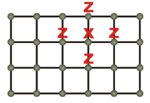
Cluster states are multipartite quantum states on a d-dimensional lattice of qubits with Ising like nearest neighbor interactions [1]. Representing the neighborhood of a qubit in a lattice by , the cluster state is given by [1]
| (1) |
where is the normalization factor and is the Pauli-Z operator applied to qubit . is an eigenstate of the stabilizer operator
| (2) |
where is the Pauli-X operator applied to qubit . Such a state can be realized by performing controlled-Z gates between qubits initialized in the states. Fig. 1 shows a 2-d cluster state on which a stabilizer operator is applied.
I.2 MBQC Computation Scheme
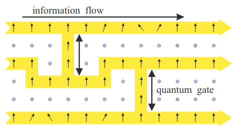
Any unitary operation on an array of qubits can be decomposed into one-qubit rotations and universal two-qubit gates (e.g. Controlled-NOT (CNOT)). Once a sufficiently large cluster state (Eq. (1)) is available, it can be used for arbitrary unitary operations using such decomposition [1, 2]. Measurements implementing the gates are performed in a sequence (imposed by dependence on previous measurements) along one dimension of the cluster state. Individual gates can be carved out in the cluster by measuring the unused qubits in the computational basis [1] (Fig. 2). Such a measurement destroys entanglement between the measured qubit and its neighbors, effectively removing it from the cluster. Formally,
| (3) |
where is the projection operator in the computational basis for qubit .
The qubit states are transported through the cluster via teleportation which is performed by measurement of qubit state in the Pauli-X () basis. To illustrate, consider Pauli-X measurement of a qubit in state () entangled with another qubit in a cluster state
| (4a) | |||
| (4b) |
where is the outcome of measurement. The state (up to a phase correction) is teleported to the other qubit in the Pauli-X basis as a result of measurement [1]. In general, the source qubit state is teleported to the target in the Pauli-X basis for odd number of teleportation steps and in the Pauli-Z basis for even number of steps.
I.2.1 Unitary Gates in MBQC
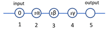
Every one-qubit rotation SU(2) admits a decomposition in Euler angles as [2]
| (5) |
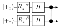
where and describe rotations about the Pauli-X and Pauli-Z axis respectively. This can be implemented using a linear chain of 5 qubits on a cluster state with input state on qubit 1 (Fig. 3). Qubits 14 are measured in the following bases [1]
| (6) |
| (7) |
where are the measurement outcomes. The implemented unitary operation is given by where describes the correction required based on measurement outcomes.
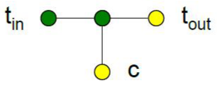
In order to have a universal set of gates, a universal 2-qubit gate is necessary. Fig. 4 shows a minimal CNOT implementation on a cluster state. The input qubit and its neighbor are measured in the Pauli-X basis, thereby implementing a CNOT (up to Pauli corrections) between control qubit and output qubit [1]. In practice, the control and target qubits are teleported to other qubits (Eq. (4)) in the cluster after computation.
A composite circuit such as in Fig. 2 can be created on the cluster which uses arbitrary one qubit rotations and CNOT gates to perform complex unitary operations on the input qubits.
II Implementations
Physical realizations of MBQC require the ability to a) Create large cluster states with a high degree of persistent entanglement between the qubits and b) Perform projective measurements on individual qubits forming the cluster in chosen eigenbases with feedforward control [2]. There have been many recent implementations of MBQC model, of which we focus on those employing superconducting qubits [8], trapped ion qubits [9] and spatio-temporal modes of squeezed photons [4]. This computation model is especially suitable for photonic quantum systems which are quite scalable but lack the ability to directly perform deterministic entangling gates. In the next few sections, we review recent efforts of implementing MBQC on the aforementioned platforms.
II.1 MBQC with Squeezed Photon Modes
One can encode quantum information in spatial and temporal modes of squeezed photon states viz., qumodes [6], which are continuous variable analogues of qubits. The Pauli-Z basis is replaced by the position quadrature basis and the Pauli-X basis is replaced by the momentum quadrature basis in this analogue. In the article [Ref. 4], the authors utilize squeezed photon states in two spatial modes and standard linear optical devices to implement a) A 2-d Gaussian photonic cluster state with a width of 6 qubits and infinite depth and b) Universal set of one and two qubit Gaussian unitaries using this cluster state.
II.1.1 Continuous Variable Cluster State
The article [Ref. 4] describes generation of a 2-d cluster state with temporal mode encoding of squeezed photon states in two spatial modes, and in Fig. 5. Optical Parametric Oscillators (OPO) are used to generate the squeezed photon states which are interfered in an unbalanced interferometer (delay of in spatial mode B) to generate a 1-d cluster state, also known as a dual rail quantum wire [5]. Each point in this cluster corresponds to a single spatial mode and temporal mode . Using a delay line of for mode of the 1-d cluster, it is coiled up into a 2-d cylindrical cluster state. High efficiency homodyne detectors are employed for both spatial modes which can make projective measurements in arbitrary quadrature basis .
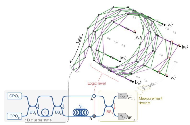
In Fig. 5, the gray nodes have odd and are measured in the quadrature basis . This projects the cluster as wires for state teleportation along the length of the 2-d cylinder [4, 5]. These form the logic levels for computation of arbitrary multimode gaussian unitaries. If Gottesman-Kitaev-Preskill (GKP) encoded qubits are available, universal fault-tolerant quantum computation is possible with this framework [6, 4].
II.1.2 Single Mode Gaussian Gates
A single mode Gaussian unitary is implemented using teleportation on a logic level of the 2-d cluster [4] (Fig. 6).
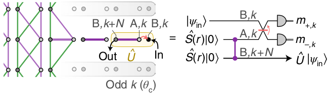
The unitary that is implemented depends on the measurement bases for the two homodyne detectors (up to a measurement dependent displacement) as [4]
| (8) |
where is the wire number, and , are the quadrature rotation and squeezing unitaries given by
| (9) |
A cascade of two such unitaries (Eq. (7)) can implement any single mode Gaussian unitary (up to a displacement) by choosing appropriate quadrature measurement bases [5].
II.1.3 Two Mode Controlled Phase Gate
To complete the universal set of Gaussian unitaries, an entangling two mode gate must be implemented. The authors demonstrate how entanglement between two logic levels and one pair of control modes can be used to implement a Gaussian unitary with two input modes [4] (Fig. 7).
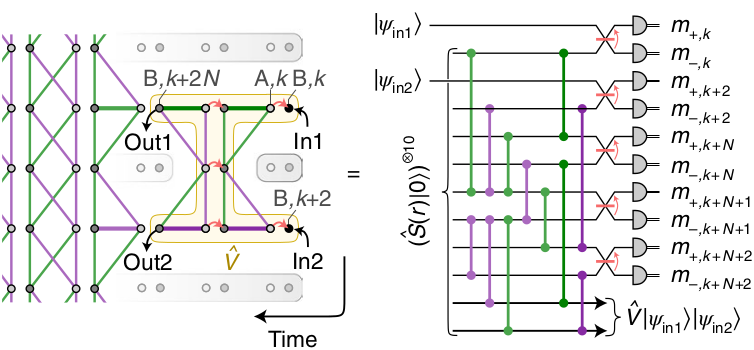
As with the single mode case, the implemented two mode unitary is determined by the measurement bases of the homodyne detectors for each temporal mode. The two mode controlled phase gate along with the single mode rotation and sqeezing gates (Eq. (8)) form a universal multimode Gaussian gate set [4]. To implement the controlled phase gate (up to known rotations) between the two input modes, choice of measurement bases are determined to be [4, 5]
| (10) |
where is the wire number of the input mode and the implemented unitary transformation is .
The above gate implementations assume infinite squeezing, which would require infinite energy and are therefore unphysical. In practice, one employs finitely squeezed photon states which introduce gate noise in the computation which accumulates as more gates are added. For one and two mode gates, the measured gate noise (after accounting for the gate noise factor of 6 dB) agrees well with the measured squeezing variance of -4.4 dB in the initial momentum quadratures. In order to make this approach scalable, some form of error correction would be required. GKP encoded qubits [6] (albeit not yet experimentally realized in optical spectrum) is one approach which could be used for fault-tolerant quantum computation with this scheme.
II.2 MBQC with Superconducting Qubits
In the article [Ref. 8], the authors propose an experimentally feasible implementation of a cluster state of the form - Eq. (1) using high fidelity gates on a 2-d lattice of superconducting qubits. They discuss the construction of a universal CNOT gate (Fig. 4) on this plaform and its expected fidelity. An alternative entangling gate is proposed which reduces the number of qubits required for CNOT gate implementation. The 2-d cluster state generated with gates is expected to be Maximally Persistent and Maximally Connected (MPMC) which could potentially lead to increased scalability of such implementations [8].
II.2.1 Cluster State with Transmon Qubits
The interaction Hamiltonian of a pair of Transmon qubits with same energy gap between ground and excited states is of the form [8]
| (11) |
For a 2-d lattice of Transmons, time evolution of interaction is given by . For and initial states , this describes a cluster state of the form
| (12) |
which differs in sign of Pauli-Z operator from Eq. (1). To express this cluster state in terms of gates, one considers initial state of a qubit to be for control of even number of qubits and for control of odd number of qubits (Fig. 8). For a 2-d lattice of Transmon qubits of size , each qubit can be represented by a vector , where is its coordinate on the lattice [8].
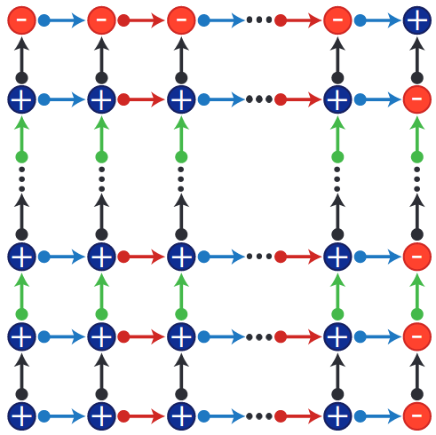
Using this, the cluster (Eq. (11)) is given by
| (13) | |||
where , , , , and , .
II.2.2 CNOT with Transmon Cluster States
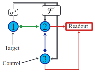
Implementation of a CNOT gate using the Transmon cluster state (Eq. (11)) follows the recipe shown in Fig. 4. The initial state of the four qubits is
| (14) |
On applying the three gates followed by measurement of qubits 1 and 2 in the Pauli-X basis, this state evolves into [8]
| (15) |
where are measurement outcomes of the respective qubits and is the measurement based correction. The authors report a gate fidelity of with an evolution time of per gate. Also, the readout and measurement process is estimated to have an error of and a processing time of per measurement. Estimated CNOT gate fidelity is therefore with an evaluation time of , which is much smaller than Transmon coherence times [8].
The authors further discuss an alternative entangling gate for generating cluster states. The action of this gate is given in block matrix form as
| (16) |
With a cluster state made using a and a gate, CNOT can be implemented with only 3 qubits (Fig. 9).
Qubits 1 and 2 are entangled with the gate (Eq. (15)) and qubits 2 and 3 are entangled with a gate to form a 3 qubit cluster state to implement CNOT. The initial state of the qubits is
| (17) |
On applying the and gates, this evolves into
| (18) |
Measurement of qubit 1 in Pauli-X basis followed by Hadamard operation on qubit 2 yields
| (19) |
where is the measurement outcome and is the measurement based correction. The authors estimate the fidelity of this CNOT to be for an evaluation time of which is a significant improvement over the 4 qubit CNOT (Eq. (14)) with a reduction in number of qubits. Beyond CNOT, the cluster state created using only gates has other useful characteristics of being - a) Maximally connected (measuring all but 2 qubits of the cluster results in a Bell state) and b) Maximally persistent (minimal product state decomposition has terms for an N qubit cluster state) [8].
II.3 MBQC with Trapped Ions
In the article [Ref. 9], authors use strings of ions in a linear Paul trap to create one and two dimensional cluster states. They employ MBQC on these cluster states to demonstrate universal one and two qubit gates. Beyond quantum computation, they also demonstrate Quantum Error Correction (QEC) on the generated cluster states using MBQC.
II.3.1 Cluster States with Trapped Ions
The electron states and of ions are used as qubit states and respectively ( nm) [9]. The ionic qubits in a linear Paul trap are initialized in state via optical pumping. The axial center of mass and stretch vibrational modes are initialized in ground state using resolved sideband cooling. The cluster states are created from the ion string using three types of interactions - a) Molmer Sorenson interaction which is a long range qubit-qubit interaction of the form , b) Single qubit phase flips and c) Hiding pulses (in this case, hiding qubit state in a different Zeeman level ) of the form .
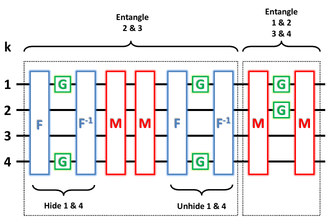
Fig. 10 [9] illustrates an equivalent quantum circuit to generate a 4 qubit 1-d cluster state using these interactions as gates. The resultant cluster state, , is equivalent to (described by Eq. (1)) up to single qubit unitary operations.
| (20) |
On performing quantum tomography of the cluster state density matrix, authors found its fidelity with respect to ideal state as being .
II.3.2 Universal Gates with Trapped Ion Cluster States
For implementation of single qubit gates, decomposition into Euler angles and measurements, described by Eq. (5) and (6), is employed with the 1-d cluster state . Using quantum state tomography, the authors obtained an average fidelity of for single qubit gates.
For illustration of two qubit gates, qubits 1 and 4 of act as inputs which are initially in state . Measuring them in bases and (Eq. (6)) results in their rotations about the Pauli-Z axis, followed by Hadamard transformation. These are subjected to the teleported gate and results are read out from qubits 2 and 3 (Fig. 11). The measurement based correction for this gate is , where and are the measurement outcomes. Using this scheme, an entangled state and a separable state were generated. Quantum state tomography yielded respective fidelities of and [9].
These implementations of a gate and single qubit rotations form a universal gate set for quantum computation.
II.3.3 Quantum Error Correction with Cluster States
Using cluster states, it is possible to implement a phase flip code capable of correcting full phase flips of of qubits forming the -qubit code-word ( is odd) [9]. The cluster state employed for error correction (Fig. 12) has the form
| (21) |
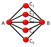
The input qubit is measured in the eigenbasis of the state to be encoded. This is followed by a measurement of code-word qubits in the Pauli-X basis which both a) teleports the encoded state to the output qubit and b) reveals the error syndrome for correction of any phase flip errors before measurement. From Eq. (20), it can be seen that if of code-word qubits are measured in state, no recovery operation is required. If, however, of code-word qubits are measured in state, the output state needs to be corrected by applying a operation on qubit .
III Discussion
MBQC achieves universal quantum computation through projective single qubit measurements on a highly entangled cluster state. This simplicity of computation comes at the expense of a large number of qubits forming the cluster state and their coherent control. Trapped ion qubits have the highest reported fidelities () for single and two qubit gates [11]. However, controlling a large number of such qubits in a single trap while maintaining coherence is extremely challenging. The most number of trapped ion qubits that have been coherently controlled so far are [10] which can implement a maximum of 5 CNOT gates on a cluster state. Superconducting qubits have reasonably good gate fidelities () [8] and have better scalability ( qubits [12]) than trapped ion qubits. While this may be sufficient for proof of concept algorithms, it is far from being useful in creating large enough cluster states for real world computations. Also, larger superconducting quantum systems require some form of error correction to reduce propagation of noise and effects of decoherence. This increases the number of physical qubits required per implemented logical qubit, further reducing the number of gates that can be faithfully implemented with MBQC. Cluster states using continuous variable states of photon modes have lower gate fidelities ( for gate noise factor of 6 dB and best reported initial squeezing variance of -17 dB with respect to vacuum) [4] than trapped ion and superconducting qubits. However, there is no fundamental limit to the size of squeezed photon cluster states with temporal mode encoding ( mode optical cluster state has been experimentally realized [7]). Quantum error correction with GKP qubit encoding [6, 4] (not yet experimentally realized in the optical spectrum) could make up for the loss in individual gate fidelities and large scale deterministic quantum computation could be achieved.
IV Conclusion
The past decade has seen significant advances in physical realizations of qubits and the scale at which they can be coherently controlled on various platforms ranging from the most commercially deployed - superconducting and trapped ion quantum systems to those employing continuous variable states of squeezed photons which have emerged only recently. Measurement based quantum computation is an approach to build a programmable quantum computer by classically adapting single qubit measurements, based on previous outcomes, on a highly entangled cluster state comprised of a large number of qubits. In this article, we review three MBQC implementations, each utilizing a different quantum computing technology viz., superconducting qubits, trapped ion qubits and spatio-temporal modes of squeezed photons. While the latter approach has lower gate fidelities among the three, the ability to create a very large photonic cluster state using such encoding allows error correction to be employed efficiently on this platform. This could make large scale universal MBQC possible in the long run.
References
- Raussendorf and Briegel [2001] R. Raussendorf and H. J. Briegel, A one-way quantum computer, Physical Review Letters 86, 5188–5191 (2001).
- Wei [2021] T.-C. Wei, Measurement-based quantum computation, Oxford Research Encyclopedia of Physics 10.1093/acrefore/9780190871994.013.31 (2021).
- Nielsen and Chuang [1997] M. A. Nielsen and I. L. Chuang, Programmable quantum gate arrays, Physical Review Letters 79, 321–324 (1997).
- Larsen et al. [2021] M. V. Larsen, X. Guo, C. R. Breum, J. S. Neergaard-Nielsen, and U. L. Andersen, Deterministic multi-mode gates on a scalable photonic quantum computing platform, Nature Physics 17, 1018–1023 (2021).
- Larsen et al. [2020] M. V. Larsen, J. S. Neergaard-Nielsen, and U. L. Andersen, Architecture and noise analysis of continuous-variable quantum gates using two-dimensional cluster states, Physical Review A 102, 10.1103/physreva.102.042608 (2020).
- Gottesman et al. [2001] D. Gottesman, A. Kitaev, and J. Preskill, Encoding a qubit in an oscillator, Physical Review A 64, 10.1103/physreva.64.012310 (2001).
- Yoshikawa et al. [2016] J.-I. Yoshikawa, S. Yokoyama, T. Kaji, C. Sornphiphatphong, Y. Shiozawa, K. Makino, and A. Furusawa, Invited article: Generation of one-million-mode continuous-variable cluster state by unlimited time-domain multiplexing, APL Photonics 1, 060801 (2016).
- Albarrán-Arriagada et al. [2018] F. Albarrán-Arriagada, G. A. Barrios, M. Sanz, G. Romero, L. Lamata, J. C. Retamal, and E. Solano, One-way quantum computing in superconducting circuits, Physical Review A 97, 10.1103/physreva.97.032320 (2018).
- Lanyon et al. [2013] B. P. Lanyon, P. Jurcevic, M. Zwerger, C. Hempel, E. A. Martinez, W. Dür, H. J. Briegel, R. Blatt, and C. F. Roos, Measurement-based quantum computation with trapped ions, Physical Review Letters 111, 10.1103/physrevlett.111.210501 (2013).
- Friis et al. [2018] N. Friis, O. Marty, C. Maier, C. Hempel, M. Holzäpfel, P. Jurcevic, M. B. Plenio, M. Huber, C. Roos, R. Blatt, and et al., Observation of entangled states of a fully controlled 20-qubit system, Physical Review X 8, 10.1103/physrevx.8.021012 (2018).
- Ballance et al. [2016] C. Ballance, T. Harty, N. Linke, M. Sepiol, and D. Lucas, High-fidelity quantum logic gates using trapped-ion hyperfine qubits, Physical Review Letters 117, 10.1103/physrevlett.117.060504 (2016).
- Ball [2021] P. Ball, First quantum computer to pack 100 qubits enters crowded race, Nature 599, 542–542 (2021).