IEEEexample:BSTcontrol
DarkGates: A Hybrid Power-Gating Architecture to Mitigate the
Performance Impact of Dark-Silicon in High Performance Processors
Abstract
To reduce the leakage power of inactive (dark) silicon components, modern processor systems shut-off these components’ power supply using low-leakage transistors, called power-gates. Unfortunately, power-gates increase the system’s power-delivery impedance and voltage guardband, limiting the system’s maximum attainable voltage (i.e., ) and, thus, the CPU core’s maximum attainable frequency (i.e., ). As a result, systems that are performance constrained by the CPU frequency (i.e., -constrained), such as high-end desktops, suffer significant performance loss due to power-gates.
To mitigate this performance loss, we propose DarkGates, a hybrid system architecture that increases the performance of -constrained systems while fulfilling their power efficiency requirements. DarkGates is based on three key techniques: i) bypassing on-chip power-gates using package-level resources (called bypass mode), ii) extending power management firmware to support operation either in bypass mode or normal mode, and iii) introducing deeper idle power states.
We implement DarkGates on an Intel Skylake microprocessor for client devices and evaluate it using a wide variety of workloads. On a real 4-core Skylake system with integrated graphics, DarkGates improves the average performance of SPEC CPU2006 workloads across all thermal design power (TDP) levels (–) between and . DarkGates maintains the performance of 3DMark workloads for desktop systems with TDP greater than while for a -TDP (the lowest TDP) desktop it experiences only a degradation. In addition, DarkGates fulfills the requirements of the ENERGY STAR and the Intel Ready Mode energy efficiency benchmarks of desktop systems.
1 Introduction
Due to the breakdown of Dennard scaling [1], the fraction of a silicon chip that can operate at the maximum attainable frequency (within a fixed power limit) reduces with each process generation [2, 3]. As a result, processor architects need to ensure that, at any point in time, a large fraction of a chip is effectively dark (i.e., idle) or dimmed (i.e., underclocked), which limits performance. To this end, architects clock-gate idle components to eliminate their dynamic power consumption or power-gate components to reduce their leakage power consumption and use the saved precious energy to power-up the necessary resources or increase their frequency.
As opposed to clock-gating, power-gating has a significant effect on a processor’s architecture. A power-gate is implemented using area-hungry low-leakage transistors that can shut off the voltage supply to a target idle circuitry. A power-gate’s impedance should be as small as possible to reduce the voltage drop it causes when the target circuit is active, as the impedance has a direct impact on the circuit’s supply voltage and power consumption. However, lowering the power-gate’s impedance increases the power-gate’s area cost. The area of such power gates is non-trivial as it grows as a function of the circuit area that is power-gated. For instance, the area of a low-impedance power-gate for a CPU core can lead to a significant increase () in the overall chip area [4, 5, 6, 7, 8, 9]. Unfortunately, since there is a limited area budget for placing power-gates, it is impractical to minimize a power-gate’s impedance and, thus, this impedance causes voltage drops on the power-delivery network. To cope with that, designers increase the voltage guardband, which results in increased power consumption when the system is active [10, 11]. This limits the maximum attainable voltage (i.e., ) and frequency (i.e., ) [12, 13], which can result in considerable performance loss for systems that are constrained by the maximum attainable CPU core frequency (i.e., -constrained), such as high-end desktops (e.g., Intel Skylake-S [14, 15, 16]).
In this paper, we propose DarkGates, a hybrid power-gating architecture to increase the performance of -constrained systems while satisfying their power efficiency requirements. DarkGates is based on three key techniques. First, DarkGates bypasses the power-gates of -constrained processors at the package level by shorting gated and un-gated CPU core power-delivery domains. This enables the sharing of 1) the decoupling capacitors of the die (i.e., Metal Insulator Metal (MIM) [17]) and the package (i.e., decaps [18]), and 2) the package routing resources among CPU cores, resulting in lower voltage drops, and improving voltage/frequency (i.e., V/F) curves.111Intel processors are individually calibrated in the factory to operate on a specific voltage/frequency and operating-condition curve specified for the individual processor [19]. Reducing the voltage guardband increases the effective voltage, which allows the processor to operate at higher frequency for the same voltage level [12]. Second, DarkGates extends the power management firmware (e.g., Pcode [20]) algorithms to operate in two modes: 1) bypass mode, which increases the CPU cores’ voltage and frequency, and 2) normal mode, which utilizes the power-gates to reduce leakage power of CPU cores. Third, DarkGates enables deeper system idle power states (i.e., package C-states) to reduce energy consumption once the entire processor is idle. For example, we include support for package C-state [21, 22] to allow turning off most of the processor’s components once the entire processor is idle, which reduces the average power consumption of energy-efficiency benchmarks.
We implement DarkGates on an Intel Skylake microprocessor222Intel Skylake [23] shares its microarchitecture with multiple processors in 2015-2020, such as Kaby Lake [24], Coffee Lake [25], Cannon Lake [26]. for client devices and evaluate it using a wide variety of SPEC CPU2006, graphics (3DMark), and energy efficiency workloads. On a 4-core Skylake processor with integrated graphics engines, DarkGates improves the performance of SPEC CPU2006 workloads by up to ( on average)333The performance gains of DarkGates are significant in highly-optimized systems like the Intel Skylake. It is important to note that all new microarchitectural optimizations (e.g., improvements in pipelining, branch prediction, and memory subsystem) in Skylake generated a average performance improvement [27] over Broadwell (one generation older than Skylake) and over Haswell (two generations older than Skylake) [27]. for a thermal design power (TDP) desktop system. DarkGates maintains the performance of 3DMark workloads for desktop systems with a TDP higher than . For a TDP (the lowest TDP) desktop, DarkGates degrades performance by only . In addition, DarkGates fulfills the ENERGY STAR (energy efficiency standard [28, 29]), the Intel Ready Mode Technology (RMT [30, 31]) energy efficiency benchmarks’ requirements.
This work makes the following contributions:
-
•
To our knowledge, DarkGates is the first work that provides a hybrid power-gating architecture to increase the performance of systems that are constrained by the maximum attainable CPU core frequency (i.e., -constrained), such as high-end desktops.
-
•
We present the implementation of DarkGates on the Intel Skylake microprocessor for client devices, showing the three key techniques required to realize DarkGates and their overhead.
-
•
We perform an experimental evaluation of DarkGates on a real 4-core Intel Skylake system and clearly establish DarkGates’ performance and energy benefits over a baseline system without it.
2 Background
We provide brief background on the architecture, power delivery networks, and design limits in modern client processors such as Intel Skylake [23, 32], Kaby Lake [24], Coffee Lake [25], and Cannon Lake [26].
2.1 Client Processor Architecture
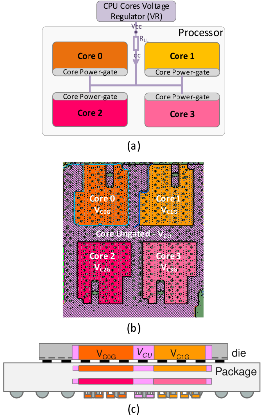
A high-end client processor is a system-on-chip (SoC) that typically integrates three main domains into a single chip: 1) compute (e.g., CPU cores and graphics engines), 2) IO, and 3) memory system. Fig. 1(a) shows the architecture used in recent Intel processors (e.g., Skylake [33, 34, 23], Coffee Lake [25], and Cannon Lake [26]) with a focus on CPU cores.
Power Management. The processor includes one central power management unit (PMU) and one local PMU per CPU core. The central PMU is responsible for several power-management activities, such as dynamic voltage and frequency scaling (DVFS) [35, 22, 36, 37]. The central PMU has several interfaces to on-chip and off-chip components, such as to 1) the motherboard voltage regulator (VR), i.e., serial voltage identification (SVID) [38, 39, 22, 20], to control the voltage level of the VR, 2) the phase-locked-loop, to control the clock frequency, and 3) each core’s local PMU, to communicate power management commands and status report. The local PMU inside the CPU core is responsible for core-specific power management, such as clock gating, power gating control, and thermal reporting.
Clocking. A phase-locked loop (PLL) supplies the clock signal to all CPU cores. All CPU cores have the same maximum clock frequency [40, 41, 42, 43].444Typically, Intel client processors that use fully-integrated voltage regulator (FIVR) power delivery, including Haswell and Ice Lake processors, have the same clock frequency domain for all cores [44, 41].
Power Gating. Power gating is a circuit-level technique to significantly reduce the leakage power of an idle circuit [10, 22, 20]. A power-gate is implemented using low-leakage transistors that shut off the input voltage to the target circuit and comes with a power-area tradeoff. A power-gate needs to be large enough to help reduce 1) the power delivery impedance (), 2) the voltage drop (i.e., drop), and 3) the operating voltage and power consumption of the target circuit when it is active. However, a power-gate for a large circuit (e.g., a CPU core) can consume significant chip area [4, 5, 6, 7, 8, 9]. A power-gate may involve an additional trade-off between leakage power consumption reduction and performance loss due to the latency to ungate the circuit (i.e., to open the power gate). Typically, the wake-up latency from the power-gated state can take a handful to tens of cycles [45, 20]. However, to reduce the worst-case peak in-rush current [46, 47, 48, 49] and voltage noise of power-delivery (e.g., / noise [50, 20, 22]) when waking up a power-gate, the power-gate controller applies a staggered wake-up technique [48] that takes tens of nanoseconds (typically, –) [45, 51, 52].
Power Budget Management (PBM). To keep the system running below a thermal design power (TDP) limit, the SoC PMU employs a power budget management (PBM) algorithm to dynamically distribute the total power budget to each SoC domain [53, 54, 38, 55, 56, 37, 57, 58, 36, 59, 60]. This allows each domain to operate within its allocated power budget. For instance, CPU cores and graphics engines in the compute domain share the same power budget. When a graphics-intensive workload is executed, the graphics engines consume most of the compute domain’s power budget.
To keep the power consumption of the compute domain within its allocated power budget, the PMU applies DVFS to 1) reduce the CPU cores’ power consumption and 2) increase the graphics engines’ performance [54, 38, 61, 39].
System Idle Power States (C-states). The Advanced Configuration and Power Interface (ACPI)555ACPI is an industry standard that is widely used for OS-directed configuration, power management, and thermal management of computing systems. defines a processor’s idle power states, commonly called C-states [62]. C-states are defined in two primary levels: 1) the component level, such as thread (), core (), and graphics () C-states, and 2) the system level, known as package C-states ( or ) [21, 22].
A package C-state defines an idle power state of the system (consisting of the processor, chipset, and external memory devices). A system enters a specific package C-state depending on each system component’s idle power state (component C-state). Various levels of package C-states exist to provide a range of power consumption levels with various techniques, such as clock gating at the uncore level or a nearly complete shutdown of the system. The ACPI standard includes recommendations on the C-states, but manufacturers are free to define their C-states and the corresponding system behavior at each C-state. In this work, we focus on the package C-states of the Intel Skylake architecture [21], but similar idle power state definitions exist in other architectures (e.g., AMD[63] and ARM [64]). Table 1 shows all package C-states of the Intel Skylake architecture and the major conditions under which the power management unit (PMU) places the system into each package C-state (a similar table exists in the Intel manual[21]).
|
Major conditions to enter the package C-state | |||||
|---|---|---|---|---|---|---|
| C0 | One or more cores or graphics engine executing instructions | |||||
| C2 |
|
|||||
| C3 |
|
|||||
| C6 |
|
|||||
| C7 |
|
|||||
| C8 |
|
|||||
| C9 |
|
|||||
| C10 |
|
2.2 Client Processor Packages and Die Sharing
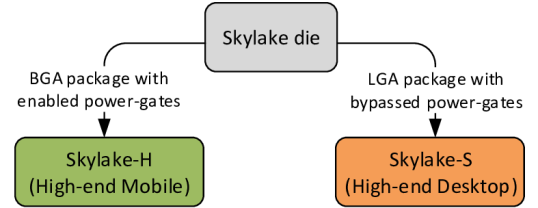
Architects of modern client processors typically build a single CPU core (with a built-in power-gate) architecture666 An Intel CPU core has nearly the same microarchitecture for client and server processors. Intel CPU core design is a single development project, leading to a master superset core. Each project has two derivatives, one for server and one for client processors [71]. that supports all dies of a client processor family, and some of the dies are used to build different processor packages targeting different segments. For example, the Intel Skylake processor for high-end mobile (i.e., Skylake-H [72]) and high-end desktop (i.e., Skylake-S [14]) processors uses a single processor die [73, 74, 55] for all TDP ranges (from [75] to [76]). Recent AMD client processors use a similar strategy [77, 78, 79, 80, 81, 82]. This design reuse is adopted for two major reasons. First, doing so allows system manufacturers to configure a processor for a specific segment using two main methods: 1) by configuring processor’s TDP (known as configurable TDP [83, 84, 85] or cTDP) to enable the processor to operate at higher or lower performance levels, depending on the available cooling capacity and desired power consumption of the system and 2) by integrating one or more dies (e.g., CPU dies, chipset, and embedded-DRAM) into a single package that is optimized for a specific market segment. For example, a land grid array (LGA [86]) package is used for desktops while a ball grid array (BGA [87]) package is used for laptops. Second, it reduces non-recurring engineering (NRE [88]) cost and design complexity to allow competitive product prices and enable the meeting of strict time-to-market requirements.
2.3 Power Delivery Network (PDN)
There are three commonly-used PDNs in recent high-end client processors [60, 89]: motherboard voltage regulators (MBVR) [37, 90, 33, 91], integrated voltage regulators (IVR) [77, 78, 79, 80, 92, 93], and low dropout voltage regulators (LDO) [17, 94, 74, 41]. We describe aspects of the MBVR PDN here due to its simplicity. As shown in Fig. 1(a), the MBVR PDN of a high-end client processor includes 1) one motherboard voltage regulator (VR) for all CPU cores, 2) a load-line impedance (), and 3) power-gates for each individual core.777 Fine-grained power-gates exist in a CPU core. For example, a power-gate is implemented in each AVX unit (e.g., AVX512 [95, 96]) inside a CPU core. All CPU cores share the same VR [37, 90, 33, 91, 43]. For more details on state-of-the-art PDNs, we refer the reader to our recent prior work [60].
Load-line. Load-line or adaptive voltage positioning [97, 98, 99, 100] is a model that describes the voltage and current relationship888In this model, short current bursts result in voltage droops [12, 101, 102], which are filtered out by the decoupling capacitors [103], while long current bursts are detected by the motherboard VR. under a given system impedance, denoted by . Fig. 2(a) describes a simplified power delivery network (PDN) model with a voltage regulator (VR), load-line (), and load (CPU Cores). is typically – for recent client processors [40, 60]. The voltage at the load is defined as , where and are the voltage and current at the VR output, respectively, as shown in Fig. 2(b). From this equation, we can observe that the voltage at the load input () decreases when the load’s current () increases. Due to this phenomenon, the PMU increases the input voltage (), i.e., applies a voltage guardband, to a level that keeps the voltage at the load () above the minimum functional voltage (i.e., ) under even the most intensive load (i.e., when all active cores are running a workload that exercises the highest possible dynamic capacitance ()). This workload is known as a power-virus [104, 105, 60] and results in the maximum possible current (). A typical application consumes a lower current than . The minimal current that the processor can consume is the leakage current () once the clocks are gated (while the supply voltage is not power-gated). In all cases where the current is lower than , the voltage drop (i.e., ) is smaller than when running a power-virus, which results in a higher load voltage than necessary (as shown in Fig. 2(b)), leading to a power loss that increases quadratically with the voltage level.
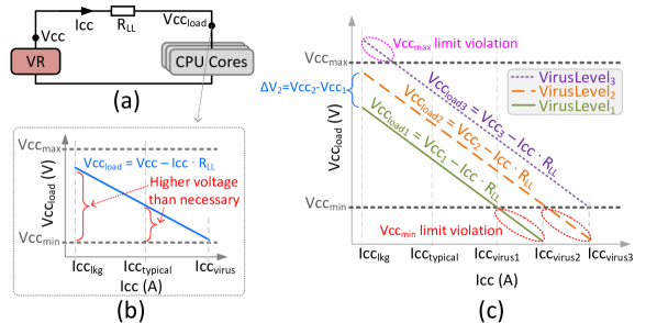
Adaptive Voltage Guardband, Iccmax, and Vccmax. To reduce the power loss resulting from a high voltage guardband when not running a power-virus, due to the load-line effect, modern processors define multiple levels of power-viruses depending on the maximum dynamic capacitance () that a system state (e.g., number of active cores and the computational intensity of running instructions) can draw. For each power-virus level, the processor applies a different voltage guardband. Fig. 2(c) illustrates the load-line model behavior of a processor with three power-virus levels denoted by , , and (where ). The three power-virus levels represent multiple scenarios. For example, , , and can represent one, two, and four active cores, respectively, for a processor with four cores. When the processor moves from one power-virus level to a higher/lower level, the processor increases/decreases the voltage by a voltage guardband (). For example, when moving from to , the processor increases the voltage by as shown (in blue text) in Fig. 2(c).
2.4 Processor Design Limits
2.4.1 Thermal Limits
We describe the most important thermal limits that constrain the performance of modern processors.
Junction Temperature () Limit. As the processor dissipates power, the temperature of the silicon junction () increases. should be kept below the maximum junction temperature () as overheating may cause permanent damage to the processor. The processor measures the temperature and applies multiple techniques (e.g., PBM [53], thermal throttling [22], and catastrophic trip temperature [20]) to ensure that the temperature remains under the limit. In the worst case, the processor automatically shuts down when the silicon junction temperature reaches its operating limit [22, 43, 39, 106, 98].
2.4.2 Power Delivery Network (PDN) Limits
There are multiple PDN limits in a modern processor. We describe the most important ones.
VR Thermal Design Current (TDC). TDC is the the continuous load current, also known as maximum continuous current, thermal current, or second power limit (i.e., PL2 [39]). TDC is the sustained current that the processor is capable of drawing indefinitely and defines the current to use for VR temperature assessment. In other words, TDC is the maximum amount of electrical current the VR must be able to supply while being thermally viable [19, 79, 109].
Power Supply and Battery Maximum Current Limit. The power supply unit (e.g., ATX power supply [110] or power brick [39]) and/or device battery that supply current to the system VRs also have current limits. For example, the third power limit (i.e., PL3) is used for battery over-current protection [39].
VR Electrical Design Current (EDC) Limit. The power delivery of a modern processor is limited by EDC, also known as the maximum instantaneous current, peak current, , or fourth power limit (i.e., PL4 [39]). EDC is the maximum amount of current at any instantaneous short period of time that can be delivered by a motherboard VR or an integrated VR (e.g., FIVR [17]). EDC limit is typically imposed by the limited maximum current that the VRs can supply [20, 17, 22, 111, 98, 112]. Exceeding the EDC limit can result in irreversible damage to the VR or the processor chip, or tripping the VR’s protection mechanism for excessive current that shuts down the system. Therefore, a combination of proactive enforcement and platform design constraints must be used to prevent system failure [20, 17, 22, 111, 98, 112, 113, 114, 115, 109].
Maximum Current per Bump/Pin. The amount of current that a processor’s die/package can consume per voltage domain is limited by the maximum current a bump/pin can support [113, 114, 115]. For example, while integrated VRs mitigate the EDC limit by enabling a reduced input current for the processor [60], the maximum current of the processor can be limited by the maximum current for a bump/pin.
Minimum Operating Voltage Limit (). Operating below the limit can cause a processor to malfunction. Therefore, modern processors implement multiple techniques to prevent the voltage from dropping below due to, for example, / voltage fluctuations [116, 20, 22, 102, 101, 117, 118].
Maximum Operational Voltage Limit (). Technology scaling has made modern integrated circuits more susceptible to reliability degradation phenomena such as Negative Bias Temperature Instability (NBTI), Electromigration (EM), and Time Dependent Dielectric Breakdown (TDDB) [119]. Degradation depends on many processes and environmental factors, but can be controlled by managing the circuit’s temperature and voltage levels [120]. Processor manufacturers define a maximum operational voltage limit () that should not be exceeded to ensure the guaranteed processor lifespan and reliability. For example, Intel allows exceeding when overclocking a system (e.g., via the BIOS [121] or the XTU tool [106]). This process is out of the processor’s reliability specification and can shorten the processor’s lifespan [121, 106, 98].
Voltage Droop Effect on Maximum Frequency (). In an active CPU core, simultaneous operations in memory and/or logic circuits demand high current flow, which creates fast transient voltage droops from the nominal voltage (). The worst-case voltage droop can degrade the maximum attainable frequency at a given voltage since this requires additional voltage (droop) guardband () above the nominal voltage to enable the CPU core to run at the target frequency. If the core voltage with the voltage guardband becomes higher than (i.e., ), the power management unit reduces , thereby reducing to keep the CPU core voltage below . Therefore, voltage guardband () has a direct effect on the CPU core .
3 Motivation
We conduct experiments on two different system setups to clearly motivate the productization of DarkGates.
Our first setup is a real Intel Broadwell processor [94], the previous generation of our target Skylake processor [55]. We configure the Broadwell processor to four Thermal Design Power (TDP) levels and frequencies using post-silicon configuration tools (see Sec. 6). In this experiment, we reduce the voltage guardband of the CPU cores by , allowing the power budget management algorithm (PBM, see Sec. 2.1) to increase the CPU cores’ frequency for a given voltage while keeping the system power consumption below TDP and the voltage below the maximum operating voltage limit (). The goal of this experiment is to evaluate the potential performance benefits of increasing CPU core clock frequency as we increase the effective voltage by reducing the voltage guardband. In this experiment, we run the SPEC CPU2006 benchmarks, both floating-point (fp) and integer (int) with base (single-core) and rate (all cores) modes [122].
Our second experimental setup is based on an in-house power delivery network simulator (see Sec. 6) that aims to evaluate the maximum possible reduction in system impedance when we bypass the power-gates.
We make two key observations from these experiments:
Observation 1. Reducing the voltage guardband (e.g., IR drop compensation) increases the effective voltage, which allows increasing the processor frequency with a negligible increase in power consumption.
Fig. 3 plots the performance impact of increasing the CPU core frequency of an Intel Broadwell system, which is enabled by increasing the effective voltage as a result of reducing the voltage guardband by . We gather our results using SPEC CPU2006 benchmarks for four TDP levels.
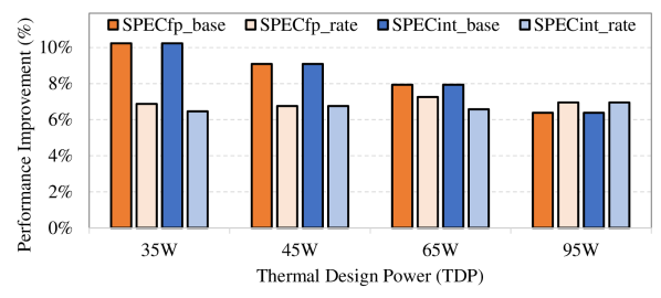
We make five key observations from Fig. 3. First, the average performance of SPECfp and SPECint benchmarks increases (by –) as the frequency of the system increases for each given TDP level. Second, the system can run at a higher frequency with the same CPU core voltage level without exceeding the TDP limit since the effective voltage increases once we reduce the voltage guardband. Third, the performance of high-TDP (i.e., ) configurations increases even though these systems are typically limited by (i.e., -constrained) since the effective voltage increases once we reduce the voltage guardband. Fourth, the lower the TDP, the higher the performance gain of the SPEC benchmarks in the base (i.e., single-core) mode. This is because the relative increase of frequency in steps of granularity until reaching the TDP limit is higher as the TDP (and baseline frequency) level is lower. Fifth, the high TDP (i.e., ) performance gain of the SPEC benchmarks in the rate (i.e., all-cores) mode is higher than that in the base mode. This is because we can increase the frequency of all cores to the maximum attainable frequency corresponding to the improved (due to the reduced the voltage guardband) without exceeding the TDP level since these systems are typically limited.
We conclude that reducing the voltage guardband can significantly improve the performance of both thermally-limited systems (e.g., TDP) and -constrained systems (e.g., TDP), based on experiments on real Intel Broadwell systems.
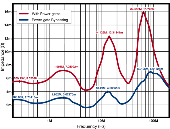
Observation 2. While power-gating is an effective technique to reduce leakage power of idle CPU cores, we observe that power-gates can significantly increase system impedance, which increases voltage drop (e.g., resistive voltage drop, drop), thereby requiring higher voltage guardbands to compensate for the higher voltage drop. Fig. 4 shows the impedance-frequency profile [123, 124, 125] of two simulated Intel Skylake systems: 1) one that uses power-gates (red) and 2) another that bypasses the power-gates (blue). The system that uses the power-gates has approximately the impedance of a system that bypasses the power-gates. Therefore, a system that uses the power-gates requires approximately the voltage guardband of a system that bypasses the power-gates.
We conclude that bypassing the power-gates can reduce system impedance by approximately , which allows reducing the voltage drop guardband by approximately .
Summary. Our experimental results clearly demonstrate that modern desktop systems face a significant challenge against achieving their potential performance and TDP utilization due to the voltage drops on power gates. Even though these voltage drops are completely preventable (e.g., if power-gates are removed), they still exist in real desktop processors. This is because reusing the same processor die for a wide variety of systems (e.g., from mobile to desktop to server) with built-in power-gates configuration is economically preferable.
Based on our key observations, we conclude that a hybrid power-gating approach is necessary to mitigate the power-gating inefficiencies in current client processors. Our goal is to provide such an approach that 1) reduces the voltage guardband overhead of power-gates in high-performance systems (e.g., high-end desktops), 2) utilizes the reduced voltage guardband to increase the frequency of the CPU cores without increasing the baseline voltage or exceeding the TDP, and 3) provides low energy consumption for battery-operated systems (e.g., laptops) and meets the energy-efficiency benchmarks’ requirements for desktop systems by reducing the leakage power consumption of idle cores.
4 DarkGates Architecture
Based on our experimental analyses, we propose DarkGates, a hybrid system architecture that increases the performance of -constrained systems while fulfilling their power efficiency requirements.
We design DarkGates with two design goals in mind: 1) reduce CPU cores’ power-delivery impedance, and, thus, voltage drop, to improve the V/F curve of high-end desktops, and 2) meet the energy efficiency requirements of desktop devices by enabling deeper package C-states.
DarkGates achieves these two goals with three key components. The first component of DarkGates is a Power-gates Bypassing technique that effectively bypasses the power-gates of -constrained processors at the package level by shorting gated and un-gated CPU core power domains. This leads to 1) sharing of the decoupling capacitors of the die and package between CPU core, and 2) sharing of package routing resources between CPU cores, resulting in lower voltage drops. The result is improved voltage/frequency (i.e., V/F) curves.
The second component of DarkGates is the improved power management firmware that is responsible for extending the power management algorithms to operate in two modes: 1) bypass mode, which increases the CPU core voltage and frequency by utilizing the improved V/F curves, and 2) normal mode, which utilizes the power-gates to reduce the leakage power of CPU cores.
The third component of DarkGates is a new deep package C-state for desktop systems that reduces energy consumption once the entire processor is idle. This leads to improved average power consumption for desktop energy-efficiency benchmarks.
The three components of DarkGates work together to increase the performance of -constrained systems while fulfilling the energy efficiency requirements. We describe them in detail in the next three subsections.
4.1 Power-gate Bypassing
The DarkGates Power-gate Bypassing technique is responsible for reducing CPU cores’ voltage drop in -constrained systems (e.g., high-end desktops) by reducing system impedance. To do so, the technique uses the same Intel Skylake die to build 1) a dedicated package for Skylake-H (used for high-end mobile systems) with the power-gates enabled and 2) a dedicated package for Skylake-S (used for high-end desktop systems) that bypasses the power-gates, as shown in Fig. 5. This architecture is feasible since client processors typically share the same die between multiple mobile and desktop products. Specifically, the same die is used for both Intel Skylake high-end mobile systems (Skylake-H) and Skylake desktop systems (Skylake-S).999Some of Skylake products even integrates an additional embedded DRAM die into the same processor package [55].
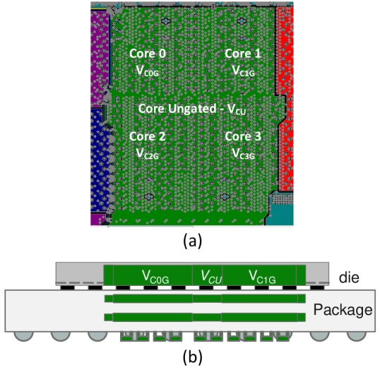
As shown in Fig. 6, the desktop package combines into a single voltage domain the five voltages used in the mobile package shown in Fig. 1 (i.e., the core ungated voltage domain () and the per-core gated voltage domains, , , , and ). To do so, the desktop package effectively shorts the four gated CPU cores’ voltage domains and the ungated voltage domain into a single domain.
The single voltage domain architecture leads to 1) sharing of the decoupling capacitors of the die (i.e., Metal Insulator Metal (MIM) [17]) and package (i.e., decaps [18]) between CPU cores, and 2) sharing of package routing resources between CPU cores. This architecture results in reducing both resistive and inductive voltage drops [126, 127, 128, 102]. As discussed in Sec. 2.4.2, reducing the voltage drop reduces the voltage guardband, which improves the voltage/frequency (i.e., V/F) curves. Improved V/F curves lead to a higher frequency (and, thus, performance) for -constrained systems.
4.2 Improved Power Management Algorithms
DarkGates architecture requires the adjustment of three main components inside the power management unit (PMU) firmware (i.e., Pcode [20]).
First, DarkGates requires the adjustment of DVFS firmware power management algorithms (e.g., P-state, Turbo) that enables the transition from one frequency/voltage operating point to another [36, 43]. Since Power-gate Bypassing (Sec. 4.1) improves the V/F curves (i.e., for a given voltage level, it increases the maximum attainable frequency), the DVFS algorithms should be adjusted to take into account the new V/F curves for desktop system101010The firmware (i.e., Pcode [20]) can recognize the target system (i.e., mobile vs. desktop) based on fuses available to the firmware. by allowing the appropriate higher frequency at any given voltage level. In particular, these changes allow increasing the maximum attainable frequency (i.e., ) for systems that are limited by the maximum reliable voltage (i.e., ). An additional advantage of the improved V/F curves is that a CPU core can run at a given frequency with a lower voltage level, which reduces the processor power consumption in the active state.
Second, DarkGates requires adjustments in the power budget management algorithm (PBM) [53, 54, 38, 55, 56, 37, 57, 58] (discussed in Sec. 2). In particular, in the DarkGates architecture, the PBM algorithm needs to take into account the additional power consumption due to the leakage of inactive cores (i.e., ungated idle CPU core), which can decrease the effective power budget that is allocated to the active cores and/or graphics engines. The reduced power budget can decrease the frequency of a thermally-limited compute domain.
Third, DarkGates can change the processor’s lifetime reliability [129, 130, 131] due to the additional power and temperature resulting from bypassing the power gates. On the one hand, DarkGates’s Power-gate Bypassing that combines cores’ otherwise separated voltage domains into a single voltage domain can improve the maximum current provided to each core since, with DarkGates, all bumps are shared between the cores, which alleviates the electromigration (EM) issues [131]. On the other hand, Power-gate Bypassing keeps cores powered-on in workloads where one or more cores are idle since these cores are normally power-gated in the baseline system (i.e., without DarkGates). Therefore, Power-gate Bypassing 1) increases the stress time of the CPU cores and 2) increases the junction temperature compared to baseline. As a result, DarkGates requires the adjustment of the reliability voltage guardband. Our reliability model shows that less than / of additional reliability voltage guardband is required to compensate for the additional stress and temperature for / (additional ), respectively.
4.3 New Package C-state for Desktops
As discussed in Sec. 2.1, desktop systems in previous processor generations of Skylake support up to the package (defined in Table 1). For example, the deepest package C-state that Haswell [31, 67] and Broadwell [68] desktop systems support is package , while Haswell [69] and Broadwell [70] for mobile systems support up to . The difference in package C-state support between desktop and mobile is due to two major reasons. First, reducing energy consumption is critical for mobile systems to meet battery life requirements for representative benchmarks (e.g., video playback, web browsing, video conferencing, light gaming [132]), while it is less critical for a desktop system. Therefore, the main desktop energy-efficiency benchmarks, such as ENERGY STAR [28, 29] and Intel Ready Mode Technology [30, 31] efficiency benchmarks, are related to reducing energy consumption once the processor is fully idle. The average power consumption needs of such benchmarks can be met with package state. Therefore, to reduce motherboard component cost and validation111111Package , for example, requires 1) dedicated components on the motherboard to turn off IO signals, 2) a special flow to move the CPU cores’ context to a dedicated area in DRAM, and 3) migrating the processor wake-up timers to the chipset to enable turning off the processor’s crystal clock[133]. effort, desktop systems are designed to support only up to package state. Second, supporting different features for different market segments is essential for product specialization and cost efficiency. For example, such differentiation prevents laptop manufacturers from using a processor that is dedicated to the desktop market segment, which is significantly cheaper than a mobile processor with equivalent TDP, to build laptop devices.
Since the CPU core’s voltage regulator is turned on in the package state (as shown in Table 1) and the power-gates are bypassed in DarkGates, the power consumption of package is significantly (more than ) higher in DarkGates than in the baseline due to the additional leakage power of the ungated CPU cores. To mitigate this issue, we extend the desktop systems with the package state [21, 22, 60]: a deeper (lower power but with higher entry/exit latency) package C-state in which the voltage regulator of the CPU cores is off, as shown in Table 1. This reduces the CPU cores’ leakage power and saves even more power in the uncore compared to the package state.
5 Implementation and Hardware Cost
First, DarkGates requires the implementation of different packages for the processor segment with power-gates (i.e., Skylake-H, used for high-end mobile system) and the processor segment that bypasses the power-gates (i.e., Skylake-S, used for high-end desktop systems). Typically, these two processor segments already have different packages: a land grid array (LGA [86]) package for Skylake-S and a ball grid array (BGA [87]) package for Skylake-H.
Second, we implement DarkGates’s power management flows in firmware121212A fully-hardware implementation is also possible. However, such power management flows are normally error-prone and require post-silicon tuning. As such, most of the power management flows are implemented within the power-management firmware (e.g., Pcode [20]). to enable the hybrid architecture on the processor die. DarkGates operates in one of two modes based on a silicon fuse [134] value: 1) bypass mode, which bypasses the power-gates to increase the voltage and frequency of the CPU cores, and 2) normal mode, which uses the power-gates to reduce the leakage power of the CPU cores. The additional firmware code to support this flow is approximately , which is less than of Intel Skylake’s die area [55].
Third, DarkGates requires the implementation of a deeper package C-state (i.e., package ) for desktop systems (i.e., Skylake-S). The package C-state power-management hardware and firmware flows are already implemented in the baseline used for mobile systems [133, 21]. Therefore, we expect no additional cost for this third component.
Like many other architectural optimizations, DarkGates also has tradeoffs and drawbacks. First, as explained in Sec. 4.2, DarkGates can affect the lifetime reliability of the processor. Second, the proposed mechanisms of DarkGates can degrade the performance of power-limited processor scenarios where few cores are active (e.g., computer graphics). This is because the additional leakage of the inactive cores reduces the power budget allocated to the graphics engines (as shown in Fig. 9). Third, DarkGates requires separate designs for the target segments. Although our baseline system have two separate packages for the target processor (i.e., Skylake-H and Skylake-S, discussed in Sec. 4.1), processor vendors that do not have two packages in the baseline architecture need to build two packages to implement DarkGates.
6 Evaluation Methodology
We use two distinct methodologies to 1) collect motivational data, demonstrating DarkGates’s potential benefits on our target processor’s (Skylake) predecessor (Broadwell) and 2) evaluate DarkGates on Skylake. The reason is that we would like to demonstrate the potential benefits of DarkGates on the previous generation processor (i.e., Broadwell) of our target Skylake processor, before we implement it in the Skylake processor.
Methodology for Collecting Motivational Data. We use a Broadwell-based system [94] to collect motivational data that shows the potential performance benefits of increasing CPU core frequency when we increase the effective voltage (i.e., by reducing the voltage guardband).
To collect the motivational data of the potential impedance improvement with Power-gate Bypassing, we model both the baseline (i.e., with power-gates enabled) and DarkGates (i.e., with Power-gate Bypassing) using an in-house power delivery network simulator (similar to [135, 136]). We create the model directly from the layout files of the package and the motherboard. We use a voltage regulator (VR) model, attached to the motherboard to allow time domain simulations. Each processor die is configured as a dynamic current load.
Methodology for Evaluating DarkGates. We implement DarkGates on the Intel Skylake [55] die that targets high-end desktop (i.e., Skylake-S [14]) and high-end mobile (i.e., Skylake-H [72]) processors. Table 2 shows the major system parameters. For our baseline and DarkGates measurements we use the Skylake-H (mobile) and Skylake-S (desktop), respectively.
Configuring the Processor. We use Intel’s In-Target Probe (ITP) [140] silicon debugger tool that connects to an Intel processor through the JTAG port [141]. We use ITP to configure processor control and status registers (CSRs) and model specific registers (MSRs). For example, we use the ITP to configure the TDP to multiple values between to . For more detail, we refer the reader to the Intel ITP manual [142, 143] and to our recent prior work [36].
Power Measurements. We measure power consumption when running energy-efficiency benchmarks by using a National Instruments Data Acquisition (NI-DAQ) card (NI-PCIe-6376 [144]), whose sampling rate is up to 3.5 Mega-samples-per-second (MS/s). Differential cables transfer multiple signals from the power supply lines on the motherboard to the NI-DAQ card in the host computer that collects the power measurements. By using NI-DAQ, we measure power on up to 8 channels simultaneously. We connect each measurement channel to one voltage regulator of the processor. The power measurement accuracy of the NI-PCIe-6376 is . Our prior works [36, 89] provide more detail on this experimental setup.
Workloads. We evaluate DarkGates with three classes of workloads that are widely used for evaluating client processors. First, to evaluate CPU core performance, we use the SPEC CPU2006 benchmarks [122] and use the SPEC CPU2006 benchmark score as the performance metric. Second, to evaluate computer graphics performance, we use the 3DMARK benchmarks [145] and use frames per second (FPS) as the performance metric. Third, to evaluate the effect of DarkGates on energy efficiency, we measure the average power consumption of two workloads that are typically used to evaluate energy consumption of desktop systems (e.g., the Skylake-S): 1) ENERGY STAR is a program that promotes energy efficiency [28, 29]. An important criterion of ENERGY STAR is that a system must automatically enter into a low power mode, defined as off, sleep, long_idle, short_idle, when it is idle. The depth of the low power mode is determined based on the idle period of the system. The energy consumption limit values are calculated using a formula that is based on the residency in each power state and the power consumption of each state. 2) An idle platform workload that places the platform into Ready Mode enabled by Intel’s Ready Mode Technology (RMT [30, 31, 146]).131313Intel Ready Mode Technology (RMT) provides an alternative to the traditional desktop sleep state, such as suspend states S3 (suspend to RAM) and S4 (suspend to disk) [22, 147, 148]. A similar feature exists in mobile devices, called Connected-Standby [133, 149, 150]. A modern desktop system enters into Ready Mode during idle periods, in which it operates at a low power state (e.g., package [151]) to reduce energy consumption while remaining connected to a communication network for usability (e.g., for email notifications and phone calls). Typically, of the time, the platform is idle (e.g., in package state) and consumes few hundreds of milliwatts [66, 70, 146]. In the remaining of the time, the platform is active (in package state) and consumes a few watts [133, 30, 31].
7 Evaluation
We present performance and average power benefits obtained with DarkGates when it is implemented in the Intel Skylake-S [14] processor compared to Skylake-H [72] baseline that has power-gates enabled. We evaluate three workload categories: CPU (Sec. 7.1), graphics (Sec. 7.2), and energy efficiency workloads (Sec. 7.3).
7.1 Evaluation of CPU Workloads
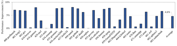
Fig. 7 reports the performance improvement of DarkGates when it is implemented in the Intel Skylake-S processor on SPEC CPU2006 base (single core) workloads over the baseline Skylake-H processor with enabled power-gates when both processors operate at their highest attainable CPU core frequencies within a TDP of . We make two key observations.
First, DarkGates improves real system performance by up to ( on average). This result is significant as it is obtained on a real Intel Skylake-S system.
Second, the performance benefit of DarkGates is positively correlated with the performance scalability141414We define performance scalability of a workload with respect to CPU frequency as the performance improvement the workload experiences with unit increase in frequency, as described in [152, 153]. of the running workload with CPU frequency. Highly-scalable workloads (i.e., those bottlenecked by CPU core frequency, such as 416.gamess and 444.namd) experience the highest performance gains. In contrast, workloads that are heavily bottlenecked by main memory, such as 410.bwaves and 433.milc, have almost no performance gain.
We conclude that DarkGates significantly improves CPU core performance by reducing the voltage guardband with Power-gate Bypassing, which improves the V/F curve and leads to higher CPU core frequency.
Fig. 8 reports the average performance improvement of DarkGates when it is implemented in the Intel Skylake-S processor on SPEC CPU2006 base (single core) and rate (all cores) workloads over the baseline Skylake-H processor with enabled power-gates when both processors operate at the highest attainable CPU core frequencies at multiple TDP levels (, , , and ). We make three key observations.
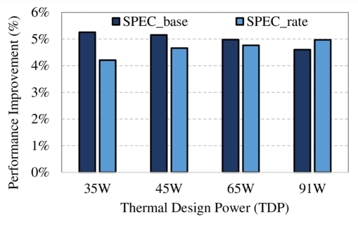
First, DarkGates improves the average real system performance of SPEC base/rate benchmarks by /, /, /, and / for , , , and TDP, respectively. This result is also significant as it is obtained on a real Intel Skylake-S system.
Second, the average performance improvement of SPEC_base benchmarks decreases as the TDP level increases. The reason is that at a low TDP (e.g., ), the processor is more thermally constrained and runs at a lower frequency than at a higher TDP (e.g., ). Therefore, the relative increase in frequency, at steps of granularity until reaching the TDP limit, is higher at a lower TDP.
Third, the average performance improvements of SPEC_rate benchmarks increases as the TDP level increases. The reason is that a high TDP is -constrained while a low TDP is thermally constrained. Therefore, a low TDP processor exceeds the TDP limit faster once all cores operate at an increased frequency compared to a high TDP processor (e.g., ) that can increase the frequency of all cores to the maximum attainable frequency with the improved (due to the reduced voltage guardband) without exceeding the thermal limit.
We conclude that DarkGates significantly improves CPU core performance by reducing the voltage guardband with Power-gate bypassing, which improves the V/F curves and leads to higher CPU core frequency for both thermally-constrained and -constrained systems.
7.2 Evaluation of Graphics Workloads
Typically, the performance of a graphics workload is highly scalable with the graphics engine frequency. When running graphics workloads, the power budget management algorithm (PBM [53, 39]) of the PMU normally allocates only to of the compute domain power budget to the CPU cores, while the graphics engine consumes the rest of the power budget [37, 38, 54]. For a client system, while running a graphics workload, one of the the CPU cores normally runs (e.g., runs the graphics driver) at the most energy-efficient frequency [22] (i.e., the maximum possible frequency at the minimum functional voltage ()) while the other cores are idle and power-gated. Since the power-gates are bypassed in a system with DarkGates, the additional leakage of the inactive cores (i.e., three CPU cores in a four-core processor) reduces the effective power budget allocated to graphics engines, which can reduce the graphics performance of a thermally-constrained system.
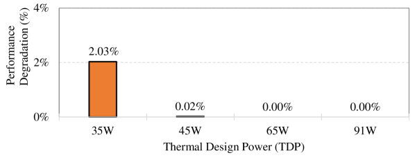
Fig. 9 shows the average performance degradation of DarkGates compared to the baseline system across different TDP levels when running the 3DMark [145] graphics workloads. We make two key observations.
First, DarkGates provides the same system performance for 3DMark for TDP levels equal to or higher than . Graphics performance is not affected with the additional power spent on the leakage of idle cores since graphics workloads in these systems are not limited by thermal constraints.
Second, for a TDP level of , DarkGates leads to only performance degradation in graphics workloads. DarkGates reduces the graphics performance for a system with TDP because this system is thermally limited. Hence, the additional leakage power of the idle CPU cores forces the PBM to reduce the frequency of the graphics engine to keep the system within the TDP limit.
We conclude that the reduced graphics engine power budget due to the additional leakage power of idle CPU cores can slightly degrade the performance of graphics workloads in thermally-limited systems, but it is not a main concern in many real systems that are not thermally-limited.
7.3 Evaluation of Energy Efficiency Workloads
Unlike CPU and graphics workloads that always benefit from higher performance, energy efficiency workloads, such as ENERGY STAR [28, 29]) and Intel Ready Mode Technology (RMT [30, 31]), have long idle phases where the system enters into idle power states (i.e., C-states [22, 62, 20, 133]). For example, in the RMT workload (discussed in Sec. 6) of the baseline system (i.e., with power-gates) the package (i.e., active) power state residency is only of the total time and the package (i.e., idle) power state residency is of the total time. Since DarkGates bypasses the power-gates, package power would significantly increase due to leakage power consumed by the idle cores. Therefore, DarkGates uses package instead of to keep the average power of these workloads within the target limits.
Fig. 10 shows the Intel Skylake-S average processor power reduction when running the two energy-efficiency workloads, ENERGY STAR and RMT, on two systems: 1) the DarkGates system, where power-gates are bypassed, and the deepest package C-state is (denoted by DarkGates), and 2) a system without DarkGates, and the deepest package C-state is (denoted by Non-DarkGates), when compared to the baseline system that includes DarkGates but limits the deepest package C-state to (denoted by DarkGates).
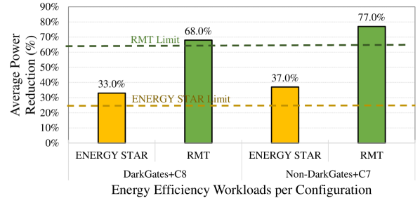
We make three key observations. First, our proposed DarkGates system (i.e., DarkGates) reduces the average power consumption of ENERGY STAR and RMT by and , respectively, on the real Intel Skylake-S system, compared to the baseline where we limit the deepest package C-state to (i.e., DarkGates).
Second, the baseline system (i.e., DarkGates) does not meet the target average power limit for both workloads. Applying package is essential to meet the target average power limit since turns off the CPU core’s voltage regulator, which greatly reduces the leakage power of the ungated CPU cores.
Third, the system without DarkGates at the deepest package C-state of (i.e., Non-DarkGates) shows lower average power consumption compared to the system with DarkGates at the deepest package C-state of (i.e., DarkGates). The higher average power of DarkGates compared to Non-DarkGates is mainly because DarkGates has higher power consumption at the power states in which some of the cores are idle, such as . These cores consume leakage power in DarkGates, but they are power-gated in Non-DarkGates.
We conclude that for energy efficiency workloads, which have fixed performance requirements, applying DarkGates with package state significantly reduces the average processor power consumption, thereby meeting the target average power requirements of the energy efficiency standards.
8 Related Work
To our knowledge, DarkGates is the first hybrid power-gating architecture for different processor market segments that increases the performance of systems constrained by the maximum attainable CPU core frequency (i.e., -constrained), such as high-end desktop systems. There are many prior works that discuss the reduction [12, 154, 155, 156, 157, 158, 159, 160, 161, 162, 163, 164, 118, 165, 117] and characterization [116, 166, 167, 163] of various design voltage guardbands. Other works focus on system impedance characterization and optimization [168, 136]. All these works are either orthogonal to DarkGates (i.e., can be applied with DarkGates) or they do not propose a practical and hybrid mitigation approach to reduce power-gates’ impedance.
Voltage Guardband Reduction. Many prior works propose multiple techniques to reduce voltage guardband [12, 154, 155, 156, 157, 158, 159, 160, 161, 162, 163, 164, 118, 165, 169, 170]. These works can be categorized into two types. The first category reduces the voltage guardband while the processors continue to function correctly [164, 118, 104], whereas the second category tolerates timing speculation errors with the aid of an error detection and recovery mechanism [165, 169, 170]. These mechanisms optimize voltage guardband using hardware and/or software sensors to reduce the operating margin for energy savings. Multiple of these guardband reduction mechanisms are already applied in the Skylake processor [72, 14, 23, 74, 34]. DarkGates can be applied orthogonally to these mechanisms since it physically optimizes the system impedance by bypassing the power-gates and sharing the power delivery resources on the package.
Voltage Guardband Characterization. Several prior works use simulation to study voltage noise in single-core [116, 166, 117] and multi-core [167, 163] CPUs. Other prior works conduct measurement-based studies of voltage noise in CPUs [160, 171, 101, 102, 118]. In our work, we use an in-house power delivery network simulator [135, 125] to characterize the system impedance and the voltage guardband. Our model is created directly from the layout files of the package and the motherboard as well as measured data from the previous Intel processor generation (Intel Broadwell [94]).
System Impedance Characterization and Optimization. Shekher et al. [136] discuss different microprocessor power gating architectures and their impact on system impedance. Engin et al. [168] present efficient algorithms for sensitivity calculations of power delivery network impedance to minimize the maximum deviation from the target impedance. Compared to DarkGates, these works do not propose practical mitigation techniques, such as Power-gate Bypassing.
9 Conclusion
We propose DarkGates, the first hybrid power-gating architecture for different processor market segments that increases the performance of systems constrained by the maximum attainable CPU core frequency (i.e., -constrained), such as high-end desktop systems. DarkGates enables optimizing and customizing the processor package, firmware, and features based on the target processor market segment needs by overcoming the limitations introduced by power gates. DarkGates is implemented in the Intel Skylake processor for high-end desktops and mobile processors (i.e., Skylake-S and Skylake-H). On a real 4-core Skylake system with integrated graphics, DarkGates improves the performance of SPEC CPU2006 workloads by up to ( on average) for the highest thermal design power (TDP) desktop system (i.e., ). DarkGates maintains the performance 3DMark graphics workloads for a desktop system with TDP higher than while a -TDP (the lowest TDP) desktop experiences only performance degradation. DarkGates fulfills the ENERGY STAR (energy efficiency standard) and the Intel Ready Mode energy efficiency benchmark requirements. We conclude that DarkGates is an effective approach to improving energy consumption and performance demands across high-end heterogeneous client processors.
Acknowledgment
We thank the anonymous reviewers of HPCA 2022 for feedback. We thank the SAFARI Research Group members for valuable feedback and the stimulating intellectual environment they provide. We acknowledge the generous gifts provided by our industrial partners: Google, Huawei, Intel, Microsoft, and VMware.
References
- [1] R. H. Dennard et al., “Design of Ion-implanted MOSFET’s with Very Small Physical Dimensions,” JSSC, 1974.
- [2] R. Merritt, “ARM CTO: Power Surge Could Create “dark silicon”,” EE Times, vol. 22, 2009.
- [3] H. Esmaeilzadeh et al., “Dark Silicon and the End of Multicore Scaling,” in ISCA, 2011.
- [4] M. Zelikson and A. Waizman, “Embedded Power Gating,” 2011, US Patent 7,880,284.
- [5] W. Shockley, “A Unipolar Field-Effect Transistor,” IRE, 1952.
- [6] P. Petrica et al., “Flicker: A Dynamically Adaptive Architecture for Power Limited Multicore Systems,” in ISCA, 2013.
- [7] D. DiTomaso et al., “Machine Learning Enabled Power-aware Network-on-chip Design,” in DATE, 2017.
- [8] A. Rahman et al., “Determination of Power Gating Granularity for FPGA Fabric,” in CICC, 2006.
- [9] D. Flynn et al., Low Power Methodology Manual: for System-on-chip Design. Springer Science & Business Media, 2007.
- [10] Z. Hu et al., “Microarchitectural Techniques for Power Gating of Execution Units,” in ISLPED, 2004.
- [11] S. Heo et al., “Dynamic Fine-Grain Leakage Reduction using Leakage-Biased Bitlines,” in ISCA, 2002.
- [12] M. Cho et al., “Postsilicon Voltage Guard-band Reduction in a 22 nm Graphics Execution Core using Adaptive Voltage Scaling and Dynamic Power Gating,” JSSC, 2016.
- [13] V. De, “Fine-grain Power Management in Manycore Processor and System-on-Chip (SoC) designs,” in ICCAD, 2015.
- [14] Intel, “6th Generation Intel Processor Families for S-Platforms,” online accessed Jul 2021 https://intel.ly/2XVdORo.
- [15] K. A. Bowman et al., “Impact of Die-to-Die and Within-Die Parameter Variations on the Clock Frequency and Throughput of Multi-core Processors,” IEEE Transactions on Very Large Scale Integration (VLSI) Systems, 2009.
- [16] J. Lee and N. S. Kim, “Optimizing Throughput of Power- and Thermal-constrained Multicore Processors using DVFS and Per-core Power-gating,” in DAC, 2009.
- [17] E. A. Burton et al., “FIVR - Fully Integrated Voltage Regulators on 4th Generation Intel® Core™ SoCs,” in APEC, 2014.
- [18] R. Jakushokas et al., Power Distribution Networks with On-Chip Decoupling Capacitors. Springer Science & Business Media, 2010.
- [19] Intel, “6th Generation Intel® Core™ Processor, External Design Specification (EDS) Addendum,” https://intel.ly/2Vthg79", May 2016.
- [20] C. Gough et al., “CPU Power Management,” in Energy Efficient Servers: Blueprints for Data Center Optimization, 2015, pp. 21–70.
- [21] Intel, “6th Generation Intel® Processor for U/Y-Platforms Datasheet,” online, accessed June 2020, https://intel.ly/37rtnU7.
- [22] J. Haj-Yahya et al., “Power Management of Modern Processors,” in Energy Efficient High Performance Processors, 2018, pp. 1–55.
- [23] I. Anati et al., “Inside 6th Gen Intel® Core™: New Microarchitecture Code Named Skylake,” in HotChips, 2016.
- [24] Wikipedia, “7th Generation Intel Core Processor Family (Kaby Lake),” online, accessed August 2020 https://en.wikipedia.org/wiki/Kaby_Lake.
- [25] Wikipedia, “8th and 9th Generation Intel Core Processor Family (Coffee Lake),” online, accessed August 2020 https://en.wikipedia.org/wiki/Coffee_Lake.
- [26] Intel, “Intel® Core i3-8121U Processor,” online, accessed Aug 2020 https://ark.intel.com/content/www/us/en/ark/products/136863/intel-core-i3-8121u-processor-4m-cache-up-to-3-20-ghz.html.
- [27] Anandtech, “Comparing IPC on Skylake: Memory Latency and CPU Benchmarks,” online, accessed July 2021, https://www.anandtech.com/show/9483/intel-skylake-review-6700k-6600k-ddr4-ddr3-ipc-6th-generation/9.
- [28] E. STAR, “Computers Specification Version 8.0,” online, accessed Jul 2021 https://bit.ly/3x44nxu.
- [29] S. ENERGY, “ENERGY STAR® Program Requirements for Computers Partner Commitments,” 2014.
- [30] Intel, “Intel Ready Mode Technology (Intel RMT),” accessed Jul 2021, https://intel.ly/3ryAwMq.
- [31] R. Bolla et al., “Assessing the Potential for Saving Energy by Impersonating Idle Networked Devices,” IEEE Journal on Selected Areas in Communications, 2016.
- [32] J. Haj-Yihia et al., “Fine-grain Power Breakdown of Modern Out-of-order Cores and its Implications on Skylake-based Systems,” TACO, 2016.
- [33] E. Fayneh et al., “4.1 14nm 6th-Generation Core Processor SoC with Low Power Consumption and Improved Performance,” in ISSCC, 2016.
- [34] A. Yasin et al., “A Metric-Guided Method for Discovering Impactful Features and Architectural Insights for Skylake-Based Processors,” TACO, 2019.
- [35] R. Gonzalez and M. Horowitz, “Energy Dissipation in General Purpose Microprocessors,” JSSC, 1996.
- [36] J. Haj-Yahya et al., “SysScale: Exploiting Multi-Domain Dynamic Voltage and Frequency Scaling for Energy Efficient Mobile Processors,” in ISCA, 2020.
- [37] E. Rotem et al., “Power Management Architecture of the 2nd Generation Intel® Core Microarchitecture, Formerly Codenamed Sandy Bridge,” in HotChips, 2011.
- [38] E. Rotem et al., “Power-management Architecture of the Intel Microarchitecture Code-named Sandy Bridge,” IEEE MICRO, 2012.
- [39] E. Rotem, “Intel Architecture, Code Name Skylake Deep Dive: A New Architecture to Manage Power Performance and Energy Efficiency,” in Intel Developer Forum, 2015.
- [40] Intel, “8th and 9th Generation Intel Core Processor Families Datasheet, Volume 1 of 2,” online, accessed Aug 2020 https://intel.ly/30VcShP.
- [41] Intel, “Ice Lake, 10th Generation Intel® Core™ Processor Families,” https://intel.ly/3frvxpK", July 2019.
- [42] Intel, “6th Generation Intel Processor Families for S-Platforms,” online accessed Aug 2020 https://intel.ly/2XVdORo.
- [43] J. Haj-Yahya et al., Energy Efficient High Performance Processors: Recent Approaches for Designing Green High Performance Computing. Springer, 2018.
- [44] D. Kanter, “Haswell FIVR Extends Battery Life,” Microprocessor Report, The Linley Group, 2013.
- [45] A. B. Kahng et al., “Many-Core Token-Based Adaptive Power Gating,” TCAD, 2013.
- [46] R. Chadha and J. Bhasker, “Architectural Techniques for Low Power,” in An ASIC Low Power Primer. Springer, 2013.
- [47] K. Usami et al., “Design and Implementation of Fine-grain Power Gating with Ground Bounce Suppression,” in VLSI Design, 2009.
- [48] K. Agarwal et al., “Power Gating With Multiple Sleep Modes,” in ISQED, 2006.
- [49] A. Abba and K. Amarender, “Improved Power Gating Technique for Leakage Power Reduction,” International Journal of Engineering and Science, 2014.
- [50] P. Larsson, “di/dt Noise in CMOS Integrated Circuits,” in Analog Design Issues in Digital VLSI Circuits and Systems. Springer, 1997.
- [51] C. J. Akl et al., “An Effective Staggered-Phase Damping Technique for Suppressing Power-Gating Resonance Noise During Mode Transition,” in ISQED, 2009.
- [52] A. B. Kahng et al., “TAP: Token-based Adaptive Power Gating,” in ISLPED, 2012.
- [53] O. Lempel, “2nd Generation Intel® Core Processor Family: Intel® Core i7, i5 and i3,” in Hot Chips, 2011.
- [54] E. Rotem et al., “Power and Thermal Constraints of Modern System-on-a-Chip Computer,” in THERMINIC, 2013.
- [55] J. Doweck et al., “Inside 6th-Generation Intel Core: New Microarchitecture Code-Named Skylake,” IEEE Micro, vol. 37, no. 2, pp. 52–62, 2017.
- [56] P. Ranganathan et al., “Ensemble-level Power Management for Dense Blade Servers,” ISCA, 2006.
- [57] H. Zhang and H. Hoffmann, “Maximizing Performance Under a Power Cap: A Comparison of Hardware, Software, and Hybrid Techniques,” in ASPLOS, 2016.
- [58] C. Isci et al., “An Analysis of Efficient Multi-core Global Power Management Policies: Maximizing Performance for a Given Power Budget,” in MICRO, 2006.
- [59] A. N. Ananthakrishnan et al., “Dynamically allocating a power budget over multiple domains of a processor,” Jul. 1 2014, uS Patent 8,769,316.
- [60] J. Haj-Yahya et al., “FlexWatts: A Power-and Workload-Aware Hybrid Power Delivery Network for Energy-Efficient Microprocessors,” in MICRO, 2020.
- [61] W. Kim et al., “System Level Analysis of Fast, per-core DVFS using On-Chip Switching Regulators,” in 2008 IEEE 14th International Symposium on High Performance Computer Architecture (ISCA). IEEE, 2008, pp. 123–134.
- [62] UEFI.org, “Advanced Configuration and Power Interface (ACPI) specification ,” online, accessed July 2021, https://bit.ly/2ToagrG.
- [63] AMD, “AMD Processor Specifications,” online, accessed June 2020, https://www.amd.com/en/products/specifications/processors.
- [64] Qualcomm Technologies, “Qualcomm Snapdragon 410E (APQ8016E) Processor Device Specification,” online, 2018, https://developer.qualcomm.com/qfile/28813/lm80-p0436-7_f_410e_proc_apq8016e_device_spec.pdf.
- [65] S. Kwa et al., “Panel Self-Refresh Technology: Decoupling Image Update from LCD Panel Refresh in Mobile Computing Systems,” in SID Symposium Digest of Technical Papers, 2012.
- [66] J. Haj-Yahya et al., “BurstLink: Techniques for Energy-Efficient Video Display for Conventional and Virtual Reality Systems,” in MICRO, 2021.
- [67] P. Hammarlund et al., “Haswell: The Fourth-Generation Intel Core Processor,” IEEE Micro, 2014.
- [68] P. Mosalikanti et al., “Low Power Analog Circuit Techniques in the 5th Generation Intel Core Microprocessor (Broadwell),” in CICC, 2015.
- [69] N. Kurd et al., “Haswell: A Family of IA 22 nm Processors,” JSSC, 2014.
- [70] A. Deval et al., “Power Management on 14 nm Intel® Core- M processor,” in COOL CHIPS, 2015.
- [71] Wikichip, “Skylake (server) - Microarchitectures - Intel,” online, accessed August 2019 https://bit.ly/2MHEWkj.
- [72] Intel, “6th Generation Intel® Core™ Processor for H-Platforms,” online accessed Jul 2021 https://intel.ly/2XVdORo.
- [73] Intel, “Intel Skylake client - Microarchitectures - Dies,” online accessed Jul 2021 https://bit.ly/3kPSdpK.
- [74] S. M. Tam et al., “Skylake-SP: A 14nm 28-Core Xeon® Processor,” in ISSCC, 2018.
- [75] Intel, “Intel Core m5-6Y57 Processor,” online, accessed Nov 2019, https://ark.intel.com/content/www/us/en/ark/products/88197/intel-core-m5-6y57-processor-4m-cache-up-to-2-80-ghz.html.
- [76] Intel, “Intel® Core™ i7-6700K Processor,” online, accessed Nov 2019, https://intel.ly/36w8d7U.
- [77] T. Singh et al., “3.2 Zen: A Next-generation High-performance 86 Core,” in ISSCC, 2017.
- [78] T. Singh et al., “Zen: An Energy-Efficient High-Performance Core,” JSSC, 2018.
- [79] T. Burd et al., “Zeppelin: An SoC for Multichip Architectures,” JSSC, 2019.
- [80] N. Beck et al., “Zeppelin: An SoC for Multichip Architectures,” in ISSCC, 2018.
- [81] AMD, “AMD Ryzen 3 4300U,” online, accessed April 2020, https://www.amd.com/en/products/apu/amd-ryzen-3-4300u.
- [82] AMD, “AMD Ryzen 7 4800H,” online, accessed April 2020, https://www.amd.com/en/products/apu/amd-ryzen-7-4800H.
- [83] Wikipedia, “Configurable TDP,” online, accessed March 2018, Mar 2019, https://en.wikipedia.org/wiki/Thermal_design_power.
- [84] Anandtech, “Configurable TDP,” online, accessed March 2020, https://www.anandtech.com/show/4830/intels-ivy-bridge-architecture-exposed/4.
- [85] S. Jahagirdar et al., “Power Management of the Third Generation Intel Core Micro Architecture Formerly Codenamed Ivy Bridge,” in HotChips, 2012.
- [86] A. Kujala et al., “Transition to Pb-free Manufacturing Using Land Grid Array Packaging Technology,” in ECTC, 2002.
- [87] B. M. Guenin et al., “Analysis of a Thermally Enhanced Ball Grid Array Package,” CPMT, 1995.
- [88] P. Magarshack and P. G. Paulin, “System-on-chip Beyond the Nanometer Wall,” in DAC, 2003.
- [89] J. Haj-Yahya et al., “IChannels: Exploiting Current Management Mechanisms to Create Covert Channels in Modern Processors,” ISCA, 2021.
- [90] S. Jahagirdar et al., “Power Management of the Third Generation Intel Core Micro Architecture Formerly Codenamed Ivy Bridge,” in HotChips, 2012.
- [91] B. Howse and R. Smith, “Tick Tock On The Rocks: Intel Delays 10nm, Adds 3rd Gen 14nm Core Product Kaby Lake,” 2015.
- [92] Z. Toprak-Deniz et al., “5.2 Distributed System of Digitally Controlled Microregulators Enabling per-core DVFS for the POWER8 TM Microprocessor,” in ISSCC, 2014.
- [93] A. A. Sinkar et al., “Low-cost Per-core Voltage Domain Support for Power-constrained High-Performance Processors,” VLSI, 2013.
- [94] A. Nalamalpu et al., “Broadwell: A Family of IA 14nm Processors,” in VLSI Circuits, 2015.
- [95] J. Mandelblat, “Technology Insight: Intel’s Next Generation Microarchitecture Code Name Skylake,” in Intel Developer Forum, San Francisco, 2015.
- [96] J. Reinders, “Intel AVX-512 Instructions,” Intel Software Developer Zone, Jun, 2017.
- [97] Intel, “Module, Voltage Regulator and Enterprise Voltage Regulator-Down (EVRD) 11.1 Design Guidelines,” Intel Corp., Santa Clara, CA, 2009.
- [98] Intel, “Voltage Regulator Module (VRM) and Enterprise Voltage Regulator-Down (EVRD) 11.1.”
- [99] J. Sun et al., “A Novel Input-side Current Sensing Method to Achieve AVP for Future VRs,” IEEE Transactions on Power Electronics, 2006.
- [100] C.-H. Tsai et al., “Switching Frequency Stabilization Techniques for Adaptive on-time Controlled Buck Converter with Adaptive Voltage Positioning Mechanism,” IEEE TPEL, 2015.
- [101] V. J. Reddi et al., “Voltage Emergency Prediction: Using Signatures to Reduce Operating Margins,” in HPCA, 2009.
- [102] V. J. Reddi et al., “Voltage Smoothing: Characterizing and Mitigating Voltage Noise in Production Processors via Software-guided Thread Scheduling,” in MICRO, 2010.
- [103] A. V. Peterchev and S. R. Sanders, “Load-line Regulation with Estimated Load-current Feedforward: Application to Microprocessor Voltage Regulators,” IEEE TPEL, 2006.
- [104] J. Haj-Yihia et al., “Compiler-directed Power Management for Superscalars,” TACO, 2015.
- [105] E. Fetzer et al., “Managing Power Consumption in a Multi-core Processor,” 2015, US Patent 9,069,555.
- [106] Intel, “Overclocking Intel® Core Processors: Taking Overclocking to the Next Level,” online, accessed Aug 2020, https://bit.ly/3iITafa.
- [107] Q. Xie et al., “Therminator: A Thermal Simulator for Smartphones Producing Accurate Chip and Skin Temperature Maps,” in ISLPED, 2014.
- [108] E. Rotem et al., “Power and Thermal Constraints of Modern System-on-a-Chip Computer,” Microelectronics Journal, 2015.
- [109] Y. Su et al., “High-efficiency Multiphase DC-DC Converters for Powering Processors with Turbo Mode Based on Configurable Current Sharing Ratios and Intelligent Phase Management,” in APEC, 2017.
- [110] D. Meisner et al., “Powernap: Eliminating Server Idle Power,” ASPLOS, 2009.
- [111] Intel, “Skylake-X, 6th Generation Intel Core X-series Processors Families,” https://intel.ly/30SP8uX, July 2019.
- [112] S. Naffziger, “Integrated Power Conversion Strategies Across Laptop Server and Graphics Products,” in Proc. Power Supply Chip, 2016, https://bit.ly/3rEbhIR.
- [113] S. Wright et al., “Characterization of Micro-bump C4 Interconnects for Si-carrier SOP Applications,” in ECTC, 2006.
- [114] C. Piguet, Low-Power CMOS Circuits: Technology, Logic Design and CAD Tools. CRC Press, 2005.
- [115] R. Zhang et al., “Architecture Implications of Pads as a Scarce Resource,” in ISCA, 2014.
- [116] R. Joseph et al., “Control Techniques to Eliminate Voltage Emergencies in High Performance Processors,” in HPCA, 2003.
- [117] D. Brooks and M. Martonosi, “Dynamic Thermal Management for High-Performance Microprocessors,” in HPCA, 2001.
- [118] C. R. Lefurgy et al., “Active Management of Timing Guardband to Save Energy in POWER7,” in MICRO, 2011.
- [119] C. Hu, “Gate Oxide Scaling Limits and Projection,” in IEDM, 1996.
- [120] P. Mercati et al., “Workload and User Experience-aware Dynamic Reliability Management in Multicore Processors,” in DAC, 2013.
- [121] Intel, “How to Overclock Your CPU from BIOS,” online, accessed Aug 2020 https://www.intel.com/content/www/us/en/gaming/resources/bios-overclocking.html.
- [122] Standard Performance Evaluation Corporation, “SPEC,” online, accessed Jul 2021, www.spec.org.
- [123] F. Mansfeld, “Recording and Analysis of AC Impedance Data for Corrosion Studies,” Corrosion, 1981.
- [124] J. Leng et al., “GPUVolt: Modeling and Characterizing Voltage Noise in GPU Architectures,” in ISLPED, 2014.
- [125] M. Ketkar and E. Chiprout, “A Microarchitecture-based Framework for Pre- and Post-silicon Power Delivery Analysis,” in MICRO, 2009.
- [126] Y. Zu et al., “Adaptive Guardband Scheduling to Improve System-Level Efficiency of the POWER7+,” in MICRO, 2015.
- [127] A. Zou et al., “Efficient and Reliable Power Delivery in Voltage-stacked Manycore System with Hybrid Charge-recycling Regulators,” in DAC, 2018.
- [128] J. Leng et al., “GPU voltage noise: Characterization and Hierarchical Smoothing of Spatial and Temporal Voltage Noise Interference in GPU Architectures,” in HPCA, 2015.
- [129] W. Song et al., “Architectural reliability: Lifetime Reliability Characterization and Management of Many-core Processors,” CAL, 2014.
- [130] K. Swaminathan et al., “Bravo: Balanced Reliability-Aware Voltage Optimization,” in HPCA, 2017.
- [131] T. Kim et al., “Learning-based Dynamic Reliability Management for Dark Silicon Processor Considering EM Effects,” in DATE, 2016.
- [132] Anandtech, “The Microsoft Surface Pro (2017) Review: Evaluation,” online, accessed March 2018, Mar 2019, https://www.anandtech.com/show/11538/the-microsoft-surface-pro-2017-review-evolution/7.
- [133] J. Haj-Yahya et al., “Techniques for Reducing the Connected-Standby Energy Consumption of Mobile Devices,” in HPCA, 2020.
- [134] S. H. Kulkarni et al., “High-Density 3-D Metal-Fuse PROM Featuring 1.37 m 2 1T1R Bit Cell in 32nm High-k Metal-Gate CMOS Technology,” in Symposium on VLSI Circuits, 2009.
- [135] K. Aygün et al., “Power Delivery for High-Performance Microprocessors.” Intel Technology Journal, 2005.
- [136] S. Shekhar et al., “Power Delivery Impedance Impact of Power Gating Schemes,” in SPI, 2016.
- [137] Intel, “Intel Core i7-6700K Processor,” online, accessed June 2021, https://intel.ly/3y4SWXA.
- [138] Intel, “Intel Core i7-6920HQ Processor,” online, accessed June 2021, https://intel.ly/3xXrrzj.
- [139] JEDEC, “DDR4 SDRAM Standard,” JEDEC Std., JESD79-4C, 2020.
- [140] Intel, “In Target Probe (ITP),” online, accessed July 2021, https://bit.ly/2qHSMbm.
- [141] M. Williams, “Low Pin-Count Debug Interfaces for Multi-Device Systems,” ARM’s Serial Wire Debug white paper, 2009.
- [142] Intel, “Intel In-Target Probe - Extended Debug Port (Intel ITP-XDP),” online, accessed December 2021, 2020, https://intel.ly/32c8DRI.
- [143] Intel, “Intel JTAG Debugger Quickstart Guide,” 2013, https://www.xlsoft.com/jp/products/intel/system/2013/xdb-quickstart-lin.pdf.
- [144] National Instruments, “NI-DAQ PCIe-6376,” online accessed 2019 http://www.ni.com/pdf/manuals/377387c.pdf.
- [145] Vantage, “3DMARK,” online, accessed March 2018, Mar 2018, http://www.futuremark.com/benchmarks/3dmarkvantage.
- [146] Intel, “Intel® Ready Mode Technology (Intel RMT),” online, accessed December 2021, https://intel.ly/3GQ7Jtb.
- [147] C. Gough et al., Energy Efficient Servers: Blueprints for Data Center Optimization. Apress, 2015.
- [148] S. Tu, “Atom™-x5/x7 series processor, codenamed cherry trail,” in 2015 IEEE Hot Chips 27 Symposium (HCS). IEEE, 2015, pp. 1–28.
- [149] J. Haj-Yihia, “Transferring Architectural Functions of a Processor to a Platform Control Hub Responsive to the Processor Entering a Deep Sleep State,” Jul. 24 2012, uS Patent 8,230,247.
- [150] J. Haj-Yihia, “Connected Standby Sleep State,” Jun. 4 2013, uS Patent 8,458,503.
- [151] Anandtech, “Intel Announces Ready Mode Technology: Using C7 for Syncing and Streaming,” online, accessed December 2021, https://www.anandtech.com/show/7871/intel-ready-mode-technology.
- [152] A. Yasin et al., “Performance Scalability Prediction,” Nov. 28 2017, US Patent 9,829,957.
- [153] J. Haj-Yihia et al., “DOEE: Dynamic Optimization Framework for Better Energy Efficiency,” in HiPC, 2015.
- [154] T.-H. Kim et al., “Silicon Odometer: An On-chip Reliability Monitor for Measuring Frequency Degradation of Digital Circuits,” JSSC, 2008.
- [155] M. Cho et al., “Aging-aware Adaptive Voltage Scaling in 22nm high-K/metal-gate tri-gate CMOS,” in CICC, 2015.
- [156] J. Leng et al., “Safe Limits on Voltage Reduction Efficiency in GPUs: a Direct Measurement Approach,” in MICRO, 2015.
- [157] A. Bacha and R. Teodorescu, “Dynamic Reduction of Voltage Margins by Leveraging On-chip ECC in Itanium II Processors,” in ISCA, 2013.
- [158] V. Von Kaenel et al., “A Voltage Reduction Technique for Battery-operated Systems,” IEEE Journal of Solid-State Circuits, 1990.
- [159] C. R. Lefurgy et al., “Active Guardband Management in Power7+ to Save Energy and Maintain Reliability,” IEEE Micro, 2013.
- [160] R. Bertran et al., “Voltage Noise in Multi-core Processors: Empirical Characterization and Optimization Opportunities,” in MICRO, 2014.
- [161] G. Papadimitriou et al., “Harnessing Voltage Margins for Energy Efficiency in Multicore CPUs,” in MICRO, 2017.
- [162] R. Thomas et al., “Core tunneling: Variation-aware voltage noise mitigation in GPUs,” in 2016 IEEE International Symposium on High Performance Computer Architecture (HPCA). IEEE, 2016, pp. 151–162.
- [163] T. N. Miller et al., “VRSync: Characterizing and Eliminating Synchronization-induced Voltage Emergencies in Many-core Processors,” in ISCA, 2012.
- [164] J. Leng et al., “Predictive Guardbanding: Program-driven Timing Margin Reduction for GPUs,” TCAD, 2020.
- [165] D. Ernst et al., “Razor: A Low-power Pipeline Based on Circuit-level Timing Speculation,” in MICRO, 2003.
- [166] M. D. Powell and T. Vijaykumar, “Pipeline Damping: a Microarchitectural Technique to Reduce Inductive Noise in Supply Voltage,” in ISCA, 2003.
- [167] M. S. Gupta et al., “Understanding Voltage Variations in Chip Multiprocessors using a Distributed Power-delivery Network,” in DATE, 2007.
- [168] A. E. Engin, “Efficient Sensitivity Calculations for Optimization of Power Delivery Network Impedance,” TEMC, 2010.
- [169] S. Das et al., “RazorII: In Situ Error Detection and Correction for PVT and SER Tolerance,” JSSC, 2008.
- [170] S. Das et al., “A Self-tuning DVS Processor Using Delay-error Detection and Correction,” JSSC, 2006.
- [171] Y. Kim et al., “AUDIT: Stress Testing the Automatic Way,” in MICRO, 2012.