Strong coupling in a Au plasmonic antenna–SiO2 layer system: a hybrid mode analysis
Abstract
A detailed analysis of the optical response of a system accommodating several coupled modes is needed for the complete understanding of the strong coupling effect. In this paper, we report on the analysis of scattering cross section spectra of Au antennas on a SiO2 layer on a Si substrate in the IR region. A classical model of coupled oscillators is used for determining the resonant energies, damping rates and coupling strengths of four phonon polariton modes in the SiO2 layer coupled to a localized surface plasmon mode in a Au antenna. The calculated Hopfield mixing coefficients then show the contribution of the individual uncoupled modes to the hybrid modes of the coupled system.
I Introduction
Plasmonic antennas have been widely used for enhancing an optical response of materials or for fabricating metamaterials with new exotic properties. In both cases, localized surface plasmon (LSP) resonances in the antennas are utilized [1]. However, at specific properties of the substrate or surrounding medium, one can observe a completely different behaviour of these antennas caused by a coupling of plasmons with other excitations, for instance phonons or excitons. The so called weak coupling regime is characterized only by minor perturbations of the shape of measured spectra and it mainly contributes to an electric near-field enhancement resulting in a stronger photon absorption and emission of the materials [2, 3]. On the other hand, the strong coupling leads to a profound shape change of antenna response spectra as new hybrid resonance modes are created in the system. One can particularly observe the Rabi splitting of the resonance peaks (and the anticrossing in dispersion relations of the modes) and eventual opening of a transparency window, as well as changes in excitation lifetimes [4].
Surface (interface) phonon polaritons (SPhP, IPhP) are excitations arising from the coupling of photons and phonons at dielectric material surfaces (interfaces), similarly to surface plasmon polaritons in conducting materials [5, 6]. The transverse optical (TO) phonons can be excited directly by light, however, their excitation efficiency in a thin layer is relatively weak (in comparison with plasmons in antennas). The longitudinal optical (LO) phonons as well as surface phonon polaritons cannot be excited directly by plane waves at normal incidence on a planar sample surface. The electric near field of plasmonic particles deposited or fabricated on a surface supporting phononic excitations may not only act in enhancing the light absorption or excitation of modes that cannot couple directly with light, but the associated localized surface plasmons can also couple with the phonons and phonon polaritons.
We present an analysis of the electromagnetic coupling between localized surface plasmons in gold rectangular antennas and phonon polaritons in a silicon dioxide thin film on a semi-infinite silicon substrate (see Fig. 1a). Even though the underlying principles in this system have been previously described [7, 8], a detailed analysis of the resultant hybrid modes based on a coupled-oscillator model, realistic SiO2 dielectric function, as well as on the calculation of the Hopfield mixing coefficients has not been performed.
II Results
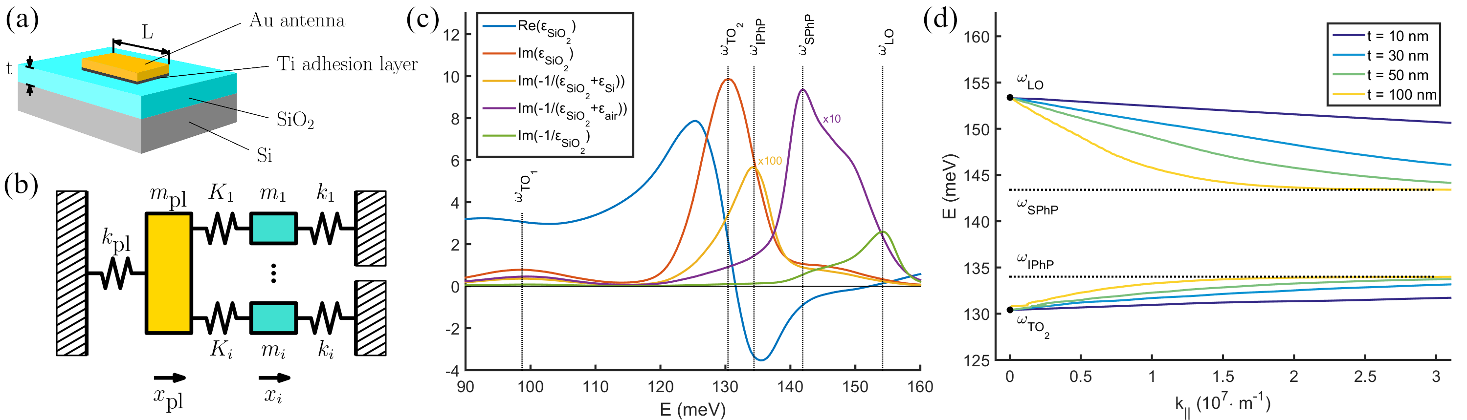
The investigation of the strong coupling effect between localized surface plasmons in metallic antennas and phonon polaritons in an absorbing dielectric layer was performed on a system depicted in Fig. 1a. It consists of a Au rectangular antenna of a variable length (between 0.8 and 3.6 m), width of 400 nm, and height of 25 nm placed on top of a SiO2 layer of a thickness (varying from 5 to 200 nm) and deposited on a Si substrate. A 5 nm-thick Ti adhesion layer between the antenna and SiO2 was used. The samples were fabricated by atomic layer deposition of SiO2 on a double side polished Si substrate, and a subsequent electron-beam lithography process followed by an electron-beam evaporation of Ti and Au. Reflectance and trasmittance spectra were measured by Fourier-transform infrared micro-spectroscopy. Finite-difference time-domain simulations (using the Lumerical software [9]) for the antenna configuration and dimensions identical with those of experimental antennas were then performed. There is a good agreement between the experimental and simulated reflectance and transmittance spectra (see Fig. S1 in Supplemental Material), both showing a similar peak splitting and opening of the transparency window around an energy of 150 meV. It enables us to preferentially use the smoother simulated spectra rather than the noisy experimental ones for fitting purposes discussed further. Moreover, the scattering cross section spectra to be fitted by curves derived from an analytical model could be acquired only from the simulations.
The realistic dielectric functions used in simulations were taken from Palik [10] for gold, titanium and silicon and from Kischkat [11] for silicon dioxide. The resonant energy of the dipolar mode of the localized surface plasmon in the antenna approximately depends linearly on the inverse value of the antenna length , and can be thus swept over the whole investigated spectral range (80-180 meV) by changing the length . There is also a higher LSP mode for longer antennas on a thinner silicon dioxide layer, however, the energy range in our analysis was limited to values below the energy of this mode so that this mode would not affect the fitting process. A multitude of phonon polariton modes are present in the silicon dioxide layer on the silicon substrate, which can be separated into two regions corresponding to the Si-O-Si stretching vibrations [12]. The silicon dioxide dielectric function and the relevant energy-loss functions are depicted in Fig. 1c. The asymmetric stretching vibration mode is described by an oscillator with the TO phonon energy meV (1052 cm-1, 9.5 m), which corresponds to the maximum of . The energy of the LO bulk phonon meV (1244 cm-1, 8.0 m) is defined by the maximum of an energy-loss function [13]. The energy of a surface phonon polariton (SPhP) meV (1146 cm-1, 8.7 m) appears at the maximum of the energy-loss function , and the energy of an interface phonon polariton (IPhP) meV (1084 cm-1, 9.2 m) appears at the maximum of the energy-loss function . The actual phonon polaritons that couple with the LSP are located either on the LO-SPhP or the TO-IPhP branch in the phonon polariton dispersion relation shown in Fig. 1d. The dispersion relation was numerically calculated using the formula in Eq. (S1) (in Supplemental Material) with a reduced damping. A symmetrical stretching vibration mode is also present at lower energies with a TO phonon energy meV (796 cm-1, 12.6 m).
In order to obtain the parameters defining the coupled system, a classical model of coupled oscillators has been employed [14]. We start with equations of motion of five damped harmonic oscillators, where four of these oscillators (corresponding to phonon polaritons, marked by the indices 1-4) couple with the fifth one (localized surface plasmon, marked by the index ) but not with each other (Fig. 1b). Moreover, we consider that an external driving force only acts on the fifth oscillator (LSP), since the direct excitation of phonon polaritons by light is negligible. The equations thus take the form:
| (1a) | ||||||||||
| (1b) | ||||||||||
| (1c) | ||||||||||
| (1d) | ||||||||||
| (1e) | ||||||||||
where , , and correspond to displacement, mass, damping constant and restoring force constant, respectively, for each oscillator. is the constant corresponding to the coupling of the -th phonon polariton with the LSP. We then define terms:
| (2a) | |||
| (2b) | |||
| (2c) | |||
| (2d) |
with and being the damping rates and resonant energies of uncoupled oscillators, the electric field of the incident light, and the effective charge representing the LSP. Furthermore, as the electric field has the form of a harmonic plane wave with frequency , all the displacements are time dependent according to .
If there was no coupling present (), the individual uncoupled oscillators would be characterised by a term proportional to their polarizability (Lorentzian oscillator)
| (3) |
The coupling can be described by the coupling strength constants [14]
| (4) |
which agree with the coupling strength constants from a Jaynes-Cummings quantum-mechanical model [15], and is the frequency splitting at the anticrossing which is characteristic for the strong coupling [14, 16].
By solving Eqs. (1) and comparing the solution with the formula for polarizability , we get the expression for the polarizability of the system in the form
| (5) |
where is the constant describing the oscillator representing the LSP and denoting the efficiency of the system excitation with the external field. Since the scattering particle supporting the localized surface plasmon has a finite volume, an effective radiation-corrected polarizability has to be considered [17]:
| (6) |
where is the speed of light in vacuum, and is the vacuum permittivity. The expression for the scattering cross section which was used for fitting the simulation results can be then calculated as [18]:
| (7) |
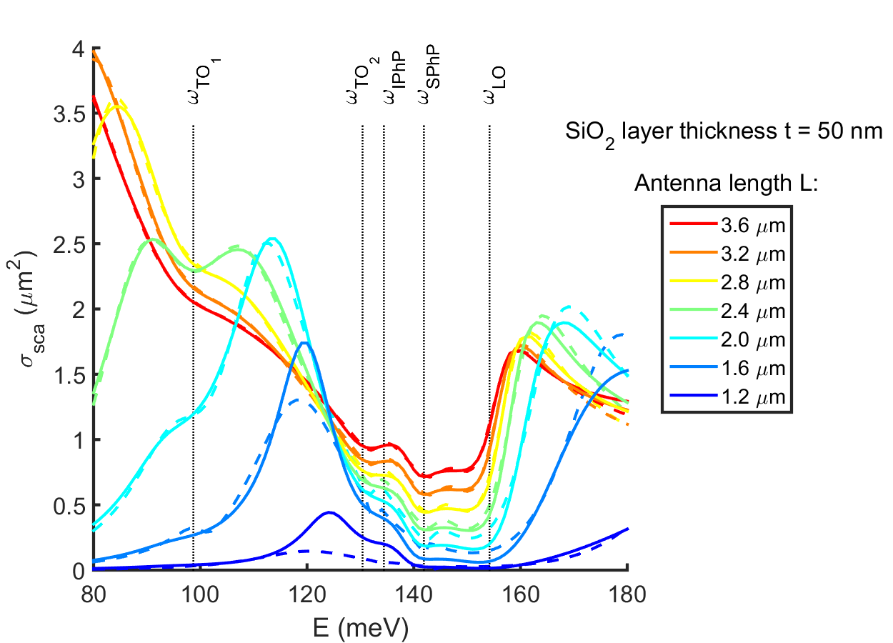
Simulated scattering cross section spectra for a constant thickness of the SiO2 layer ( nm) and different antenna lengths are shown in Fig. 2 (solid lines). The spectra for the constant length m and different thickness are in Fig. S2 in Supplemental Material. With the increasing antenna length the plasmon resonance redshifts. However, the peak splitting (minima) is in all spectra at almost the same energies, which corresponds to the coupling of the phonon polariton modes with the plasmon resonance mode. By fitting the spectra with Eq. (7) (dashed lines in Fig. 2), we obtain the resonant energies and damping rates of the original localized surface plasmon and phonon polaritons (which can be then assigned to the individual phonons), and coupling strengths . The coupling phonon polariton modes are at energies around 101 meV (TO1), 132 meV (TO2), 144 meV (SPhP) and 152 meV (LO). Only four oscillators for phonons were used during the fitting, since the addition of another oscillator for IPhP made a negligible impact, pointing to the conclusion that either the TO2 phonon excitation is much stronger and thus the effect of coupling of the plasmon with the IPhP mode is unobservable [7], or that all the TO2-IPhP branch mode energies are so close to each other that it can be described by a single oscillator during the fitting process.
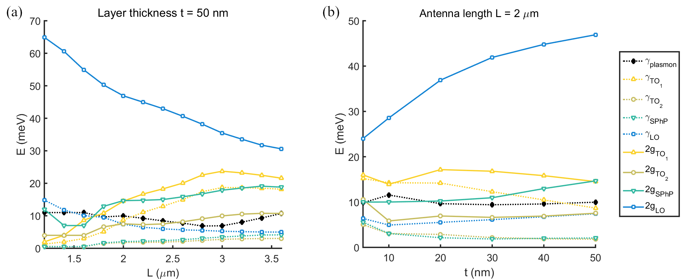
The dependence of the coupling strengths and damping rates on the Au antenna length or the SiO2 layer thickness is shown in Fig. 3. The condition for the strong coupling stated as [16, 19] is fulfilled for the LO phonon mode, with the highest coupling strength corresponding to the splitting of around 50-60 meV for smaller and larger . The coupling of the other modes with the LSP (with around 20 meV, around 8 meV, and around 20 meV) is also observable in the scattering cross section spectra, however, the values of the coupling strengths are not particularly larger than the damping rates, therefore there is just an onset of the strong coupling regime for these modes.
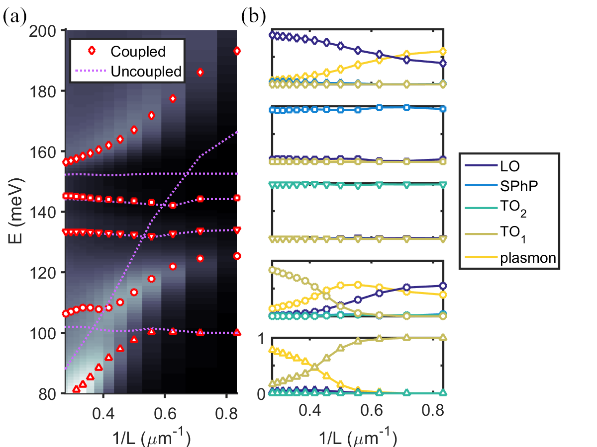
The parameters obtained from fitting can be further utilized for an analysis of the hybrid modes given by the coupling [20, 21, 22]. A simplified matrix describing the system
| (8) |
can be constructed either directly from the Jaynes-Cummings quantum mechanical model or from the model presented here by assuming that all the energies (both and ) are close to each other [19] and omitting the damping. The eigenvalues of the matrix correspond to the energies of the new hybrid modes (peak positions in the spectra). The eigenvectors , where for the five eigenvalues, can be further utilized to find the relative contribution of individual uncoupled plasmon or phonon polariton modes into the hybrid modes. The absolute squares of the eigenvector components (, , , and ) give the Hopfield mixing coefficients which express the fractional contribution of the individual modes to the new hybrid mode [20, 21, 22]. Fig. 4a shows the peak positions (eigenvalues of the matrix , red points) laid over the plot given by the simulated scattering cross section (in the background), together with the uncoupled mode energies from fitting (dotted lines). The plots of the Hopfield mixing coefficients in Fig. 4b are linked to the corresponding branches in Fig. 4a. They show a gradual shift of the major contributor to the two lowest and the one highest energy coupled modes (e.g. the lowest branch being mainly plasmon-like for longer antennas and phonon-like for shorter antennas) with . Interestingly, the two branches around 132 and 144 meV seem to be composed only from TO2 and SPhP modes, respectively, even though they are coupled with the plasmons as there is a visible minimum (splitting) in the scattering cross section spectra and the coupling strengths have a comparable magnitude to that of the TO1 mode. This could be possibly explained by the LO phonon being a dominant mode producing the whole splitting (transparency window) between 120-180 meV and TO2 and SPhP having only a small effect and being described rather as only weakly coupled. Contrarily, the TO1 mode is at the onset of strong coupling, since it is not affected by the LO mode (which is far away) and produces anticrossing behaviour around 100 meV, even though having a similar coupling strength and damping rate as TO2 or SPhP modes. Moreover, for a thinner layer the splitting caused by the LO mode is smaller, and the splitting (anticrossing) around the TO2 mode starts to be more noticeable together with a slight contribution of the TO2 mode to the lower energy coupled mode, as shown in Fig. S3.
III Conclusions
We have presented the method for analysis of the optical response of a coupled system of localized surface plasmons and phonon polaritons by utilizing the classical coupled-oscillator model and the Hopfield mixing coefficients, providing a better understanding of the strong coupling effect. The fitting of the scattering cross section spectra by the model revealed coupling of LSPs in the Au antenna with several modes in the SiO2 layer. More specifically, the onset of the strong coupling around an energy of 100 meV, observable as the peak splitting, can be described as an interaction of a single phonon with a plasmon mode. However, the spectral features between 120 and 180 meV are caused by tranverse and longitudinal optical phonons and surface phonon polaritons, of which the strong coupling of the LO mode (with a peak splitting of up to 60 meV) is the most prominent interaction effect, influencing also the coupling of the other modes. Even though there should also be an interface phonon polariton mode, it has not been used in the fitting of the spectra due to its negligible effect. The calculation of the Hopfield mixing coefficients describing the contribution of the uncoupled modes to the hybrid modes further supports these results. There is a major contribution of the LO mode to the hybrid modes surrounding the transparency window, while the TO2 and SPhP modes seem not to mix with the other modes despite the minor splitting in the spectra, hinting to only a weak coupling regime of those two modes.
Acknowledgements.
We acknowledge the support by the Czech Science Foundation (Grant No.*20-28573S*), European Commission (H2020-Twininning project No. 810626 – SINNCE, M-ERA NET HYSUCAP/TACR-TH71020004),*BUT* – specific research No.*FSI-S-20-648*5, and Ministry of Education, Youth and Sports of the Czech Republic (CzechNanoLab Research Infrastructure – LM2018110).References
- Spektor et al. [2015] G. Spektor, A. David, B. Gjonaj, G. Bartal, and M. Orenstein, Metafocusing by a metaspiral plasmonic lens, Nano letters 15, 5739 (2015).
- Alonso-González et al. [2012] P. Alonso-González, P. Albella, M. Schnell, J. Chen, F. Huth, A. García-Etxarri, F. Casanova, F. Golmar, L. Arzubiaga, L. Hueso, J. Aizpurua, and R. Hillenbrand, Resolving the electromagnetic mechanism of surface-enhanced light scattering at single hot spots, Nature Communications 3, 10.1038/ncomms1674 (2012).
- Moskovits [2005] M. Moskovits, Surface-enhanced Raman spectroscopy: a brief retrospective, Journal of Raman Spectroscopy: An International Journal for Original Work in all Aspects of Raman Spectroscopy, Including Higher Order Processes, and also Brillouin and Rayleigh Scattering 36, 485 (2005).
- Dintinger et al. [2005] J. Dintinger, S. Klein, F. Bustos, W. L. Barnes, and T. Ebbesen, Strong coupling between surface plasmon-polaritons and organic molecules in subwavelength hole arrays, Physical Review B 71, 035424 (2005).
- Caldwell et al. [2015] J. D. Caldwell, L. Lindsay, V. Giannini, I. Vurgaftman, T. L. Reinecke, S. A. Maier, and O. J. Glembocki, Low-loss, infrared and terahertz nanophotonics using surface phonon polaritons, Nanophotonics 4, 44 (2015).
- Yu and Cardona [2010] P. Yu and M. Cardona, Fundamentals of semiconductors : physics and materials properties (Springer, 2010).
- Huck et al. [2016] C. Huck, J. Vogt, T. Neuman, T. Nagao, R. Hillenbrand, J. Aizpurua, A. Pucci, and F. Neubrech, Strong coupling between phonon-polaritons and plasmonic nanorods, Optics express 24, 25528 (2016).
- Shelton et al. [2011] D. J. Shelton, I. Brener, J. C. Ginn, M. B. Sinclair, D. W. Peters, K. R. Coffey, and G. D. Boreman, Strong coupling between nanoscale metamaterials and phonons, Nano letters 11, 2104 (2011).
- [9] Lumerical Inc., www.lumerical.com.
- Palik [1998] E. D. Palik, Handbook of optical constants of solids, Vol. 3 (Academic press, 1998).
- Kischkat et al. [2012] J. Kischkat, S. Peters, B. Gruska, M. Semtsiv, M. Chashnikova, M. Klinkmüller, O. Fedosenko, S. Machulik, A. Aleksandrova, G. Monastyrskyi, et al., Mid-infrared optical properties of thin films of aluminum oxide, titanium dioxide, silicon dioxide, aluminum nitride, and silicon nitride, Applied optics 51, 6789 (2012).
- Gunde [2000] M. K. Gunde, Vibrational modes in amorphous silicon dioxide, Physica B: Condensed Matter 292, 286 (2000).
- Lüth [2001] H. Lüth, Solid surfaces, interfaces and thin films, Vol. 4 (Springer, 2001).
- Novotny [2010] L. Novotny, Strong coupling, energy splitting, and level crossings: A classical perspective, American Journal of Physics 78, 1199 (2010).
- Casanova et al. [2010] J. Casanova, G. Romero, I. Lizuain, J. J. García-Ripoll, and E. Solano, Deep strong coupling regime of the Jaynes-Cummings model, Physical review letters 105, 263603 (2010).
- Törmä and Barnes [2014] P. Törmä and W. L. Barnes, Strong coupling between surface plasmon polaritons and emitters: a review, Reports on Progress in Physics 78, 013901 (2014).
- Jackson [1999] J. D. Jackson, Classical Electrodynamics (Wiley, New York, 1999).
- Novotny and Hecht [2012] L. Novotny and B. Hecht, Principles of nano-optics (Cambridge university press, 2012).
- Autore et al. [2018] M. Autore, P. Li, I. Dolado, F. J. Alfaro-Mozaz, R. Esteban, A. Atxabal, F. Casanova, L. E. Hueso, P. Alonso-González, J. Aizpurua, et al., Boron nitride nanoresonators for phonon-enhanced molecular vibrational spectroscopy at the strong coupling limit, Light, science & applications 7, 17172 (2018).
- Břínek et al. [2018] L. Břínek, M. Kvapil, T. Šamořil, M. Hrtoň, R. Kalousek, V. Křápek, J. Spousta, P. Dub, P. Varga, and T. Šikola, Plasmon Resonances of Mid-IR Antennas on Absorbing Substrate: Optimization of Localized Plasmon-Enhanced Absorption upon Strong Coupling Effect, ACS Photonics 5, 4378 (2018).
- Slootsky et al. [2014] M. Slootsky, X. Liu, V. M. Menon, and S. R. Forrest, Room temperature Frenkel-Wannier-Mott hybridization of degenerate excitons in a strongly coupled microcavity, Physical review letters 112, 076401 (2014).
- Zhang et al. [2021] W. Zhang, J.-B. You, J. Liu, X. Xiong, Z. Li, C. E. Png, L. Wu, C.-W. Qiu, and Z.-K. Zhou, Steering Room-Temperature Plexcitonic Strong Coupling: A Diexcitonic Perspective, Nano Letters 21, 8979 (2021).