Numerical optimization of amplitude-modulated pulses in microwave-driven entanglement generation
Abstract
Microwave control of trapped ions can provide an implementation of high-fidelity two-qubit gates free from errors induced by photon scattering. Furthermore, microwave conductors may be embedded into a scalable trap structure, providing the chip-level integration of control that is desirable for scaling. Recent developments have demonstrated how amplitude modulation of the gate drive can permit a two-qubit entangling operation to become robust against motional mode noise and other experimental imperfections. Here, we discuss a method for the numerical optimization of the microwave pulse envelope to produce gate pulses with improved resilience, faster operation and higher energy efficiency.
Keywords: trapped ions, quantum computing, quantum information processing, two-qubit gates, amplitude modulation, entanglement
⋆MD and GZ contributed equally to this work.
†Present address: National Institute of Standards and Technology, Boulder, Colorado 80305, USA
‡christian.ospelkaus@iqo.uni-hannover.de
1 Introduction
Trapped ions are a leading scalable platform for the implementation of quantum algorithms [1, 2, 3]. Scaling any hardware will ultimately require the implementation of quantum error correction codes [4, 5] to prevent error propagation in large-scale algorithms. This will require quantum gates with fidelities beyond the fault-tolerance threshold [6, 7]. A universal set of quantum gates requires single-qubit gates and one two-qubit gate capable of entanglement generation [8]. For trapped ions, single-qubit operations have already reached error rates well below [9, 10]. A major experimental challenge is to obtain similar error rates for a two-qubit entangling gate. Experimental results are approaching the desired gate fidelity [11, 12, 13, 14] where large-scale error correction could reasonably be implemented [15, 16].
Unfortunately, two-qubit entangling gates can be affected by a variety of imperfections, the seriousness of which depend on the type of gate itself. Quantum control methods allow to analytically or numerically improve the performance of the gate, providing resilience and robustness against specific error sources. The specifics of the protocol implemented depend on the source of errors addressed for the gate.
In the case of noise connected to the qubit frequency, the most straightforward control protocol is the Hahn echo [17], but depending on the gate protocol more advanced schemes can be required. There are multiple protocols which employ pulsed dynamic decoupling [18, 19] and continuous dynamic decoupling [20] or other forms of error suppression [21, 22].
In the case of errors connected to the ion’s state of motion, several methods have been studied: Walsh modulation [23], multi-tone fields [24, 25, 26], phase modulation [27], frequency modulation [28] and amplitude modulation [29, 30]. The latter has been extensively used in laser-driven operations [29, 30, 31, 32], and more recently demonstrated for microwave-driven operations [33].
Hybrid schemes to provide simultaneous insensitivity to motional mode and qubit frequency instabilities have been proposed [34, 35].
Here we present a method to perform numerical optimization of a pulse envelope for amplitude-modulation in Mølmer-Sørensen entangling gates. The method described here allows the area enclosed in phase-space trajectories of the ion motion to be insensitive to trap and pulse parameters, allowing faster operations while maintaining the previously demonstrated insensitivity. The energy used for the gate is minimized, an important feature in the case of microwave driven operations [36, 37, 38], especially in cryogenic environments where cooling power should be limited [39, 40], as excess energy could affect the stability of the mode.
2 Numerical optimization
The numerical method presented here aims to optimize the amplitude of the bichromatic microwave field which drives the Mølmer-Sørensen entangling gate [41, 42, 43]. The gate dynamics can be described by introducing a basic control function . Such functions modulate the motion in phase space of the harmonic oscillator describing the ions’ secular motion
| (1) |
where is the detuning from the motional mode frequency of the bichromatic drive. At a specific time , the gate time, the trajectory described in (1) should ideally constitute a loop with an enclosed area . In case the trajectory does not return to the initial phase space position or the enclosed area differs from the gate fidelity will be affected by an error. As a fidelity measure we use the overlap of the generated state with the target Bell state. Other measures exist, and should eventually be considered too. In terms of the area is
| (2) |
with the kernel
| (3) |
with Furthermore, as previously stated, it is of interest to minimize the energy dissipated in the trap. Since the gate Rabi rate is proportional to the current flowing in the trap conductors, the energy will be proportional to
| (4) |
The optimization done here generates pulses that have a fixed area in phase space while minimizing the energy. Since both quantities are given by quadratic expressions, this amounts to finding the pulse which satisfies the generalized eigenvalue equation
| (5) |
with the largest possible eigenvalue . Here and are the operators representing the quadratic expressions and . That is , so is given by the above kernel , and is the identity operator. This general form will also apply in the discretized version that we solve numerically, although will then be more complicated. One can use the scheme to achieve additional desirable features, for example, smoothness. To that end we will add to a small penalty term with the norm square of , i.e., use a so-called Sobolev norm. Moreover, it is easy to include arbitrary linear constraints , by solving the generalized eigenvalue problem on a subspace. The most important of these is that the loop closes in phase space, i.e., in 1. We can also ensure that small variations in the detuning to not disturb the loop closure, by demanding that the derivatives of and with respect to vanish as well. That is we demand to be orthogonal to the following four functions
and ensure that because
| (6) |
and
| (7) |
Therefore they ensure a closed loop in phase space. The functions and are the derivatives of and with respect to and ensure that small variations in the detuning leave the loop unchanged. Potentially the amount of excluded functions can be increased. One might consider to include even higher derivatives of and for more stability with respect to the detuning in higher derivatives. We restricted ourselves to these four functions to not make the subspace too large, which would come at the expense of increased energy. This derivative strategy is reminiscent of the approach used to construct composite pulses. However, here it is used to construct the shape of the pulse rather than the phases of the composite sequence of pulses, with the benefit of having much shorter driving field duration.
For a numerical analysis, the gate time interval is discretized into pieces, with cut points In the optimization, various functions have to be evaluated at these points. The following basis is used for
| (8) |
Note that , so the expansion coefficients in
| (9) |
are exactly the values . These coefficients give the gate Rabi rate value at a specific moment . When are the excluded functions, the projection onto their complement is
| (10) |
where is the corresponding Gram matrix, and is it’s matrix inverse. The energy kernel of (4) is adjusted with the Sobolev norm so that
| (11) |
to ensure a soft start, necessary to avoid pseudopotential kicks from parasitic electric fields [44]. In the following we restrict ourselves to the case . This specific choice was made in order to ensure a soft start without increasing the energy too much. If then a soft start of the pulse is not guaranteed.
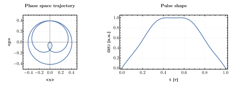
The objective is to minimize the energy while keeping the area constant. This can be achieved by solving the generalized eigenvalue problem where and are the kernels mentioned above but projected onto the subspace with the projector defined earlier (10). The eigenvector with the largest eigenvalue provides the coefficients that have the best ratio of energy to area. Higher orders are therefore not considered. The ratio of and defines the corresponding eigenvector because the area kernel is constructed for a given detuning. Therefore for all detunings the area kernel is different. This leads to diverse eigenvectors. For the Mølmer-Sørensen gate it needs to fulfill where is an integer number. The possibility to perform a gate starts with . A possible eigenvector and its phase space trajectory is shown in Fig. 1.
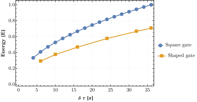
Fig. 2 shows the energy dissipated in the trap for the square and the shaped gates. The energy is calculated with (4) for both shapes. For the same value of , the optimized pulses dissipate approximately 25 less than the square pulses energy. The main reason for this is the soft start of the pulses, which lowers the integral of over the gate time . The largest energy corresponds to the square pulse with . All energies in Fig. 2 are normalized to this value. The dissipated energy contributes to the gate errors because it leads to motional instability. Therefore pulses that dissipate less energy are preferred to minimize effects such as the mode frequency chirp [45].
3 Experimental demonstration
The experimental demonstration of the entangling gate pulse envelopes obtained using the method described in Sec. 1 has been done in the setup described in [45, 46]. The experiments have been performed on 9Be+ ions at a static magnetic field of mT, where the chosen qubit transition, , is first-order field independent. The enhanced frequency stability of the transition is reflected in a long coherence time of the qubit [47]. Doppler cooling and detection is performed with a nm laser resonant with the transition. For integrated microwave control, three conductors are embedded in the surface-electrode trap: two conductors for driving carrier transitions and one for sideband operations. The latter is designed [48] to produce a strong magnetic field gradient optimized for spin-motional coupling. The microwave amplitude modulation setup is described in [33]. For implementation purposes optimized pulse envelopes are produced with , , , and . For a maximum gate Rabi rate of kHz, the pulse durations are , , , and .
The maximally entangled states generated have been analyzed with a partial tomography procedure [49]. All state populations have been estimated from the global fluorescence emission of the ions by using appropriately placed thresholds in the photon count histograms. Experimental results are reported in Fig. 3 and compared with the expected theoretical performance of a standard square-pulse gate. and rotations used for state preparation, shelving and analysis are implemented using composite pulses. Specifically, the U5a sequence has been used for pulses [50] and the pulse sequence for the analysis pulse [51].
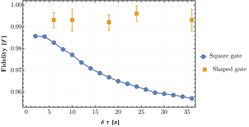
The fidelities for simulated square-pulse Mølmer-Sørensen gates have been obtained using the error model developed in [45] and adjusted to reflect the experimental conditions. For the addressed out-of-phase radial motional mode, we considered an average motional state occupation of , a heating rate of and an intrinsic linewidth of . A single spectator in-phase mode was included, detuned by kHz with . The experiments have been performed without a warm-up pulse employed in earlier experiments to minimize motional mode frequency fluctuations, called ”frequency chirp”, induced by thermal transients in the trap [45]. The absence of this thermalization process before the gate means that the full frequency chirp has to be included in the simulation with a ramp of for up to . For each simulated point, the gate detuning has been optimized to yield the highest resulting fidelity. Parameters regarding the imperfection of the microwave pulse shape have been left as in the original model. We place a lower bound of 0.5 s on the internal-state coherence time. Variations of the qubit transition frequency have not been included as an error source in the simulation. The reason behind this choice is that ideally the gate is performed at the same point of minimal AC-Zeeman shift (ACZS) as for the amplitude-modulated gates. Note that despite this choice, it is expected that fast variations, or non-perfect calibrations, of the ACZS could lead to errors in AM gates. Further details of the error model are described in [52].
The results shown in Fig. 3 consistently show infidelities below . The large difference in the fidelity between amplitude-modulated and square-pulse gates at the highest values of demonstrates the resilience of the optimized gates.
4 Conclusions
The numerical method described here provides the capability to generate optimized amplitude-modulated gates that are robust with respect to disturbances of the motional mode. In addition, the algorithm minimizes the energy per pulse used to generate a maximally entangled Bell state in microwave driven operations. The experimental verification has been done by implementing multiple optimized pulse envelopes, consistently demonstrating an infidelity in the range. All gates produced with this method were faster than the one described in our previous work [33], the fastest of which had .
In the future, such shaped gates can be integrated with other protocols, such as dynamic decoupling, to suppress gate errors connected to the ACZS affecting the qubit frequency during gate operation. The integration of these decoupling protocols would ease the requirements concerning the minimization of the ACZS and provide resilience to small changes of the ACZS. To further increase the gate speed, it is necessary to increase the magnetic field gradient driving the gate. One possibility is given by advanced three-dimensional microwave structures [53]. Given the large errors resulting from the global detection of two-ion fluorescence, more advanced schemes of error characterization are required, possibly in a computational contest, such as benchmarking methods [54, 55, 56].
References
References
- [1] Bermudez A, Xu X, Nigmatullin R, O’Gorman J, Negnevitsky V, Schindler P, Monz T, Poschinger U G, Hempel C, Home J, Schmidt-Kaler F, Biercuk M, Blatt R, Benjamin S and Müller M 2017 Physical Review X 7 041061 URL https://link.aps.org/doi/10.1103/PhysRevX.7.041061
- [2] Bruzewicz C D, Chiaverini J, McConnell R and Sage J M 2019 Applied Physics Reviews 6 021314 URL https://aip.scitation.org/doi/10.1063/1.5088164
- [3] Pino J M, Dreiling J M, Figgatt C, Gaebler J P, Moses S A, Allman M S, Baldwin C H, Foss-Feig M, Hayes D, Mayer K, Ryan-Anderson C and Neyenhuis B 2021 Nature 592 209–213 ISSN 1476-4687 URL https://www.nature.com/articles/s41586-021-03318-4
- [4] Steane A M 1996 Physical Review Letters 77 793–797 ISSN 0031-9007, 1079-7114 URL http://link.aps.org/doi/10.1103/PhysRevLett.77.793
- [5] Knill E 2005 Nature 434 39–44 ISSN 1476-4687 URL https://www.nature.com/articles/nature03350
- [6] Preskill John 1998 Proceedings of the Royal Society of London. Series A: Mathematical, Physical and Engineering Sciences 454 385–410 URL https://royalsocietypublishing.org/doi/10.1098/rspa.1998.0167
- [7] Knill E 2010 Nature 463 441–443 ISSN 1476-4687 URL https://www.nature.com/articles/463441a
- [8] DiVincenzo D P 1995 Physical Review A 51 1015–1022 URL https://link.aps.org/doi/10.1103/PhysRevA.51.1015
- [9] Brown K R, Wilson A C, Colombe Y, Ospelkaus C, Meier A M, Knill E, Leibfried D and Wineland D J 2011 Physical Review A 84 030303 URL http://link.aps.org/doi/10.1103/PhysRevA.84.030303
- [10] Harty T, Allcock D, Ballance C, Guidoni L, Janacek H, Linke N, Stacey D and Lucas D 2014 Physical Review Letters 113 220501 URL http://link.aps.org/doi/10.1103/PhysRevLett.113.220501
- [11] Ballance C, Harty T, Linke N, Sepiol M and Lucas D 2016 Physical Review Letters 117 060504 URL https://link.aps.org/doi/10.1103/PhysRevLett.117.060504
- [12] Gaebler J, Tan T, Lin Y, Wan Y, Bowler R, Keith A, Glancy S, Coakley K, Knill E, Leibfried D and Wineland D 2016 Physical Review Letters 117 060505 URL http://link.aps.org/doi/10.1103/PhysRevLett.117.060505
- [13] Srinivas R, Burd S C, Knaack H M, Sutherland R T, Kwiatkowski A, Glancy S, Knill E, Wineland D J, Leibfried D, Wilson A C, Allcock D T C and Slichter D H 2021 Nature 597 209–213 ISSN 1476-4687 URL https://www.nature.com/articles/s41586-021-03809-4
- [14] Clark C R, Tinkey H N, Sawyer B C, Meier A M, Burkhardt K A, Seck C M, Shappert C M, Guise N D, Volin C E, Fallek S D, Hayden H T, Rellergert W G and Brown K R 2021 Physical Review Letters 127 130505 URL https://link.aps.org/doi/10.1103/PhysRevLett.127.130505
- [15] Ryan-Anderson C, Bohnet J G, Lee K, Gresh D, Hankin A, Gaebler J P, Francois D, Chernoguzov A, Lucchetti D, Brown N C, Gatterman T M, Halit S K, Gilmore K, Gerber J, Neyenhuis B, Hayes D and Stutz R P 2021 arXiv:2107.07505 [quant-ph] URL http://arxiv.org/abs/2107.07505
- [16] Hilder J, Pijn D, Onishchenko O, Stahl A, Orth M, Lekitsch B, Rodriguez-Blanco A, Müller M, Schmidt-Kaler F and Poschinger U 2021 arXiv:2107.06368 [quant-ph] URL http://arxiv.org/abs/2107.06368
- [17] Hahn E L 1950 Physical Review 80 580–594 URL https://link.aps.org/doi/10.1103/PhysRev.80.580
- [18] Manovitz T, Rotem A, Shaniv R, Cohen I, Shapira Y, Akerman N, Retzker A and Ozeri R 2017 Physical Review Letters 119 220505 URL https://link.aps.org/doi/10.1103/PhysRevLett.119.220505
- [19] Arrazola I, Casanova J, Pedernales J S, Wang Z Y, Solano E and Plenio M B 2018 Physical Review A 97 052312 URL https://link.aps.org/doi/10.1103/PhysRevA.97.052312
- [20] Bermudez A, Schmidt P O, Plenio M B and Retzker A 2012 Physical Review A 85 040302 URL http://link.aps.org/doi/10.1103/PhysRevA.85.040302
- [21] Ivanov S S and Vitanov N V 2015 Physical Review A 92 022333 ISSN 1050-2947, 1094-1622 URL https://link.aps.org/doi/10.1103/PhysRevA.92.022333
- [22] Arrazola I, Plenio M, Solano E and Casanova J 2020 Physical Review Applied 13 024068 ISSN 2331-7019 URL https://link.aps.org/doi/10.1103/PhysRevApplied.13.024068
- [23] Hayes D, Clark S M, Debnath S, Hucul D, Inlek I V, Lee K W, Quraishi Q and Monroe C 2012 Physical Review Letters 109 020503
- [24] Haddadfarshi F and Mintert F 2016 New Journal of Physics 18 123007 ISSN 1367-2630 URL http://stacks.iop.org/1367-2630/18/i=12/a=123007?key=crossref.930cce36a98a5c2febdce848c3dc66f7
- [25] Shapira Y, Shaniv R, Manovitz T, Akerman N and Ozeri R 2018 Physical Review Letters 121 180502 ISSN 0031-9007, 1079-7114
- [26] Webb A E, Webster S C, Collingbourne S, Bretaud D, Lawrence A M, Weidt S, Mintert F and Hensinger W K 2018 Physical Review Letters 121 180501 ISSN 0031-9007, 1079-7114
- [27] Milne A R, Edmunds C L, Hempel C, Frey V, Mavadia S and Biercuk M J 2018 arXiv:1808.10462 [quant-ph] URL http://arxiv.org/abs/1808.10462
- [28] Leung P H and Brown K R 2018 Physical Review A 98 032318 URL https://link.aps.org/doi/10.1103/PhysRevA.98.032318
- [29] Zhu S L, Monroe C and Duan L M 2006 Physical Review Letters 97 050505 ISSN 0031-9007, 1079-7114 URL https://link.aps.org/doi/10.1103/PhysRevLett.97.050505
- [30] Roos C F 2008 New Journal of Physics 10 013002 ISSN 1367-2630 URL http://stacks.iop.org/1367-2630/10/i=1/a=013002?key=crossref.0cd67d9408fea34e2d258aeb1f179ffd
- [31] Schäfer V M, Ballance C J, Thirumalai K, Stephenson L J, Ballance T G, Steane A M and Lucas D M 2018 Nature 555 75–78 ISSN 1476-4687 URL https://www.nature.com/articles/nature25737
- [32] Figgatt C, Ostrander A, Linke N M, Landsman K A, Zhu D, Maslov D and Monroe C 2019 Nature 572 368 ISSN 0028-0836, 1476-4687
- [33] Zarantonello G, Hahn H, Morgner J, Schulte M, Bautista-Salvador A, Werner R F, Hammerer K and Ospelkaus C 2019 Physical Review Letters 123 260503 ISSN 0031-9007, 1079-7114 URL https://link.aps.org/doi/10.1103/PhysRevLett.123.260503
- [34] Lishman J and Mintert F 2020 Physical Review Research 2 033117 URL https://link.aps.org/doi/10.1103/PhysRevResearch.2.033117
- [35] Sutherland R T, Srinivas R, Burd S C, Knaack H M, Wilson A C, Wineland D J, Leibfried D, Allcock D T C, Slichter D H and Libby S B 2020 Physical Review A 101 042334 URL https://link.aps.org/doi/10.1103/PhysRevA.101.042334
- [36] Mintert F and Wunderlich C 2001 Physical Review Letters 87 257904 URL http://link.aps.org/doi/10.1103/PhysRevLett.87.257904
- [37] Ospelkaus C, Langer C E, Amini J M, Brown K R, Leibfried D and Wineland D J 2008 Physical Review Letters 101 090502 URL http://link.aps.org/doi/10.1103/PhysRevLett.101.090502
- [38] Sutherland R T, Srinivas R, Burd S C, Leibfried D, Wilson A C, Wineland D J, Allcock D T C, Slichter D H and Libby S B 2019 New Journal of Physics 21 033033 ISSN 1367-2630 URL http://stacks.iop.org/1367-2630/21/i=3/a=033033?key=crossref.0a38be9f23524daf3aca334ab6d309da
- [39] Srinivas R 2020 Laser-free trapped-ion quantum logic with a radiofrequency magnetic field gradient PhD Thesis University of Colorado Boulder
- [40] Dubielzig T 2021 Ultra-low vibration closed-cycle cryogenic surface-electrode ion trap apparatus Ph.D. thesis Gottfried Wilhelm Leibniz Universität Hannover
- [41] Mølmer K and Sørensen A 1999 Physical Review Letters 82 1835 URL http://link.aps.org/doi/10.1103/PhysRevLett.82.1835
- [42] Solano E, de Matos Filho R L and Zagury N 1999 Physical Review A 59 R2539 URL http://link.aps.org/doi/10.1103/PhysRevA.59.R2539
- [43] Milburn G, Schneider S and James D 2000 Fortschritte der Physik 48 801–810 ISSN 00158208 URL http://onlinelibrary.wiley.com/doi/10.1002/1521-3978(200009)48:9/11%3C801::AID-PROP801%3E3.0.CO;2-1/abstract
- [44] Warring U, Ospelkaus C, Colombe Y, Brown K R, Amini J M, Carsjens M, Leibfried D and Wineland D J 2013 Physical Review A 87 013437 URL http://link.aps.org/doi/10.1103/PhysRevA.87.013437
- [45] Hahn H, Zarantonello G, Schulte M, Bautista-Salvador A, Hammerer K and Ospelkaus C 2019 npj Quantum Information 5 70 ISSN 2056-6387 URL https://www.nature.com/articles/s41534-019-0184-5
- [46] Hahn H 2019 Two-qubit microwave quantum logic gate with Be ions in scalable surface-electrode ion traps PhD Thesis Gottfried Wilhelm Leibniz Universität Hannover
- [47] Langer C, Ozeri R, Jost J D, Chiaverini J, DeMarco B, Ben-Kish A, Blakestad R B, Britton J, Hume D B, Itano W M, Leibfried D, Reichle R, Rosenband T, Schaetz T, Schmidt P O and Wineland D J 2005 Physical Review Letters 95 060502 URL http://link.aps.org/doi/10.1103/PhysRevLett.95.060502
- [48] Carsjens M, Kohnen M, Dubielzig T and Ospelkaus C 2014 Applied Physics B 114 243–250 ISSN 0946-2171, 1432-0649 URL http://link.springer.com/article/10.1007/s00340-013-5689-6
- [49] Sackett C A, Kielpinski D, King B E, Langer C, Meyer V, Myatt C J, Rowe M, Turchette Q A, Itano W M, Wineland D J and Monroe C 2000 Nature 404 256–259 ISSN 0028-0836 URL http://dx.doi.org/10.1038/35005011
- [50] Genov G T, Schraft D, Halfmann T and Vitanov N V 2014 Physical Review Letters 113 043001 URL https://link.aps.org/doi/10.1103/PhysRevLett.113.043001
- [51] Torosov B T and Vitanov N V 2011 Physical Review A 83 053420 ISSN 1050-2947, 1094-1622 URL https://link.aps.org/doi/10.1103/PhysRevA.83.053420
- [52] Schulte M 2020 Entanglement in Ramsey interferometry, optical atomic clocks and trapped ions PhD Thesis Gottfried Wilhelm Leibniz Universität Hannover
- [53] Hahn H, Zarantonello G, Bautista-Salvador A, Wahnschaffe M, Kohnen M, Schoebel J, Schmidt P O and Ospelkaus C 2019 Applied Physics B 125 154 ISSN 1432-0649 URL https://doi.org/10.1007/s00340-019-7265-1
- [54] Gaebler J P, Meier A M, Tan T R, Bowler R, Lin Y, Hanneke D, Jost J D, Home J P, Knill E, Leibfried D and Wineland D J 2012 Physical Review Letters 108 260503 URL http://link.aps.org/doi/10.1103/PhysRevLett.108.260503
- [55] Erhard A, Wallman J J, Postler L, Meth M, Stricker R, Martinez E A, Schindler P, Monz T, Emerson J and Blatt R 2019 Nature Communications 10 1–7 ISSN 2041-1723 URL https://www.nature.com/articles/s41467-019-13068-7
- [56] Baldwin C H, Bjork B J, Gaebler J P, Hayes D and Stack D 2020 Physical Review Research 2 013317 ISSN 2643-1564 URL https://link.aps.org/doi/10.1103/PhysRevResearch.2.013317