In-plane magnetic field induced density wave states
near quantum spin Hall phase transitions
Abstract
We study the influence of an in-plane magnetic field and Coulomb interactions on the physics of quantum spin Hall insulators, like those in InAs/GaSb and HgTe/CdTe quantum wells. Using a Hartree-Fock mean-field theory approximation, we calculate phase diagrams as functions of the band gap, band hybridization, and magnetic field strength. We show that when the band hybridization is weak, the system is unstable against the formation of density wave states. As the strength of the in-plane magnetic field increases, the density-wave region of the phase diagram expands and distinct density-wave states appear. We discuss possible experimental implications of our results.
I Introduction
The quantum spin Hall (QSH) insulator is a topologically nontrivial state of matter characterized by gapless helical edge states protected by time-reversal symmetry [1, 2]. It was first realized in HgTe/CdTe quantum wells [3, 4], and later also in other systems like InAs/GaSb quantum wells [5, 6, 7]. Theoretically the physics of QSH insulators is captured by the Bernevig-Hughes-Zhang (BHZ) model [3], which is a single-particle theory that ignores interactions and works well in the limit of strong band hybridization. Interactions become important when the BHZ model band hybridization parameter is small, as can be appreciated by considering the limit , where coherence between conduction and valence bands, or exciton condensation, occurs spontaneously when the band gap is smaller than the exciton binding energy [8, 9, 10, 11, 12, 13, 14, 15]. Recent experiments [16, 17, 18] have shown excitonic behavior in InAs/GaSb quantum wells. The interplay between interactions and topology can lead to interesting new phases near the QSH phase transition [19, 20, 21, 22], which have so far been only lightly explored.
In this paper we study how an in-plane magnetic field modifies the phase diagram studied in Ref. 22, which contains time-reversal symmetry-breaking electron nematic phases. Due to the spatial separation between electron and hole layers, an in-plane magnetic field shifts the conduction and valence bands in opposite directions in momentum space. Intuitively this opposite shift effectively increases the band gap and reduces the hybridization between the electron and hole bands. When interactions are neglected, an in-plane magnetic field drives the system into a semi-metallic state. Using a Hartree-Fock mean-field theory, we show that the nematic states instead break translational symmetry and become density-wave states. At stronger tunneling an in-plane magnetic field can drive the system through a variety of different phases, including quantum anomalous Hall states with and without density-wave order.
This paper is organized as follows: In Section II we formulate the mean-field theory we use to describe interaction effects, and explain how we allow the possibility of translational symmetry breaking. In Section III we summarize our results by presenting phase diagrams that depend on three parameters: band gap, hybridization, and the strength of in-plane magnetic field. Finally in Section IV we discuss the relationship between our work and potential future experiments, and its relationship to excitonic density-wave states that have been identified, often controversially, in bulk three-dimensional crystals.
II Mean-field theory
We use a four-band BHZ model [3, 5] to describe the InAs/GaSb quantum wells. The field operators are four-component spinors , where and denote the conduction and valence bands, and and denote two opposite spins. The single-particle physics of the system under an in-plane magnetic field is described by the modified BHZ Hamiltonian [23, 21]
| (1) |
where the two matrices and can be explicitly expressed as
| (2) |
and are the effective masses of electrons and holes, is the band gap, is the strength of hybridization between the conduction and valence bands, and is the momentum shift due to the in-plane magnetic field. Without the magnetic field, and are time-reversal partners:
| (3) |
When an in-plane magnetic field is applied to electron and hole layers separated by an interlayer distance , the conduction and valence bands are shifted in momentum by by Peierls substitution. The in-plane magnetic field breaks the time-reversal symmetry of the system and induces orbital moments. The electrons and holes interact via the Coulomb interaction
| (4) |
where is the area of the two-dimensional system, and are band and spin indices respectively, is the intralayer Coulomb interaction, is the interlayer Coulomb interaction at interlayer distance , and is the dielectric constant of the surrounding three-dimensional material.
Anticipating the possibility of translational symmetry breaking [21] along the direction of , we divide momentum space into slabs separated by . Then apart from the band and spin indices , the basis states are labeled by an integer and a quasi-momentum () that lies within the first quasi-one-dimensional Brillouin zone. Together and refer to the plane-wave state with momentum .
We use a Hartree-Fock mean-field theory to describe the Coulomb interaction. The Hartree term is
| (5) |
where the density matrix is defined relative to the density matrix with valence bands filled and conduction bands empty:
| (6) |
For , the Hartree term accounts for the electrostatic potential energy difference between the electron and hole layers, where
| (7) |
is the exciton density. The Fock term
| (8) |
accounts for the exchange interaction. Together, the system is described by the mean-field Hamiltonian
| (9) |
Below we express lengths and energies in terms of characteristic scales and , where is the reduced effective mass. This model approximates InAs/GaSb quantum wells if we choose , and [24], which implies that and . We assume the interlayer distance . For an in-plane magnetic field of strength , the momentum shift . For simplicity in Eq. (2) we neglect the particle-hole asymmetry which does not affect the ground state physics, and perform numerical calculations with .
III Phase diagrams
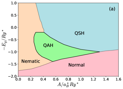
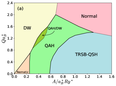
Given , and , the ground state of the system can be obtained by solving the Hartree-Fock equations self-consistently and finding the lowest-energy solution. The case has been studied in detail in Ref. 22, and the phase diagram is reproduced in Fig. 1(a). At the number of particles in the conduction and valence bands are conserved separately. When the bare energy gap is reduced below the exciton binding energy, the excitons condense and coherence is established spontaneously between the conduction and valence bands. This order survives at finite , where it breaks rotational symmetry by establishing coherence between -conduction and -valence electrons, and also breaks time-reversal symmetry by doing so in a spin-dependent manner. In Fig. 1 we refer to this state as the nematic insulator state. At large , single-particle physics dominates and the system undergoes a topological phase transition between the QSH and normal insulators as varies. At moderate values of , the transition between QSH and normal insulators occurs via an intermediate quantum anomalous Hall state (QAH) state with broken time-reversal symmetry and a nonzero Chern number 111In this summary, we have ignored some minor phases that occur in a small region of the phase diagram near the line..
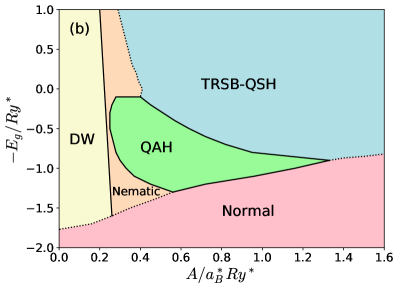
When an in-plane magnetic field is applied, the QSH state is no longer protected by time-reversal symmetry. In the simplified BHZ Hamiltonian (1) we use here, the two spins are decoupled and a spin Chern number can be defined to distinguish QSH and normal insulators [27]. In the more general case where spin is not a good quantum number, it has been shown that [28, 29, 30] the spin Chern number can remain well-defined as a robust topological invariant. For this reason the QSH-normal insulator transition still exists. In order to distinguish these two cases we refer to the finite- QSH state as a time-reversal symmetry-breaking (TRSB) QSH state [29].
At small hybridization the momentum-shifted conduction and valence bands tend to establish coherence by breaking translational symmetry to achieve better Fermi surface nesting, forming density wave (DW) states with wavevector . We find that at small but finite the energetically preferred state is one in which pairing is between opposite spins, so the order parameter is where denotes the spin opposite to . At the density matrix element is nonzero only for . When the band-hybridization parameter is non-zero, on the the other hand, it is nonzero for any and , although the exciton condensate order parameter () is always much larger than the other three (, , and ) density-matrix elements. When the magnetic field is weak, the DW state exists only near and undergoes a first-order phase transition to the nematic insulator state, which does not have finite- pairing, as increases (see Fig. 1(b)). The nematic insulator phase is characterized by the order parameter ; the coherence that is established does not accomodate the momentum-space shifts of the conduction and valence bands. We retain the term nematic insulator used at even though rotational symmetry has already been explicitly broken by the in-plane magnetic field.
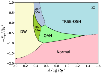
The boundary between the magnetic-field-stabilized DW state and the nematic insulator state moves rapidly to the right as the magnetic field strength increases, eventually squeezing the nematic insulator state out of the phase diagram as shown in Fig. 1(c). Near the DW phase boundary neighboring the TRSB-QSH and QAH phase regions, two new phases appear 222We have ignored some minor phases that appear near the phase boundaries. We find that the QSH/DW and QAH/DW phases are more stable as the magnetic field strength increases. that also break translational symmetry along the -direction. These two states are connected to the TRSB-QSH and QAH states via continuous phase transitions, and we label them as QSH/DW and QAH/DW states respectively, for reasons that will become clear later. Like the DW state, both the QSH/DW and QAH/DW states have order parameters of the form . Unlike the DW state, however, the largest pairing terms in the QSH/DW state are between conduction and conduction, and valence and valence bands, yielding order parameters . The QAH/DW state has different up-to-down and down-to-up spin pairings: , with one, say , resembling the DW state with the largest element appearing at , and the other () resembling the QSH/DW state with the largest element at . The transitions between the DW, QAH/DW and QSH/DW states are all first-order transitions.
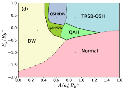
As continues to increase, the three density-wave regions keep expanding and the QAH region shrinks as shown in Fig. 1(d). While the transitions between the TRSB-QSH, QAH and normal insulator states stay largely unchanged, the phase boundaries slowly move towards larger and smaller as increases, consistent with the intuition that the momentum shift between conduction and valence bands effectively increases the band gap and weakens the band hybridization.
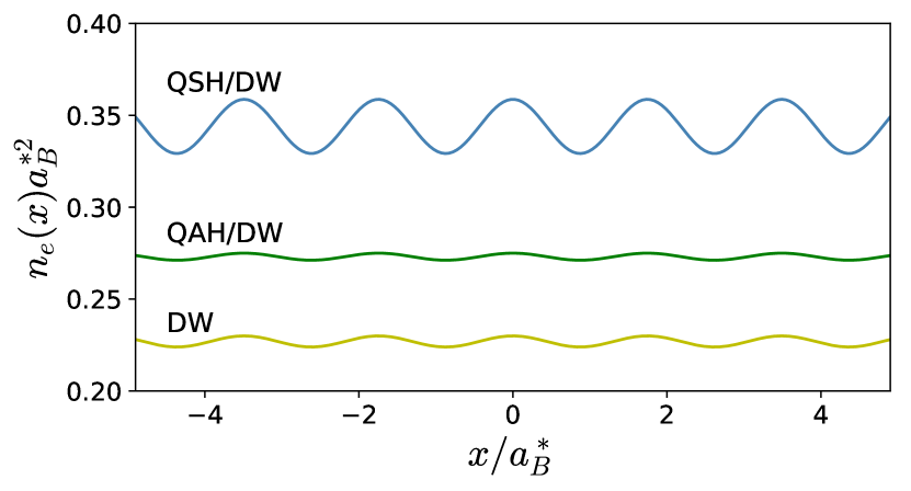
For , the ground states are true exciton condensates and ordering does not lead to charge-density variations in either layer even if it occurs at . For , the situation changes. The charge densities in the electron and hole layers (in units of ) are related to the density matrices by
| (10) |
At , the only nonzero density-matrix elements in Eq. (10) are , so the charge density is uniform in each layer. When , still vanishes because only opposite spins in neighboring Brillouin zones are coupled. However, can be nonzero when , so the charge density in each layer oscillates periodically in space, with periodicity . Fig. 2 shows the charge density distribution in the electron layer of the three density-wave states. We see that the QSH/DW state has larger spatial charge density fluctuations than the other density-wave states, as expected because of its conduction-to-conduction and valence-to-valence band couplings. In our calculation with , the charge density in the hole layer is exactly the opposite of that in the electron layer due to the particle-hole symmetry present for this parameter choice. In the general case there is partial cancellation between the charge densities in the two layers, resulting in a weak total charge density oscillation in space.
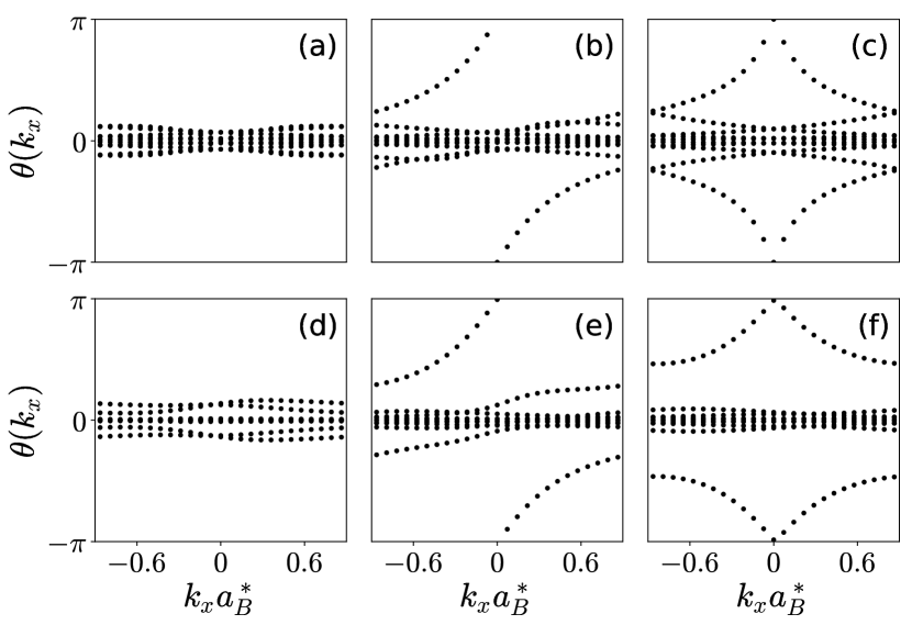

The topological properties of these phases can be studied by performing Wilson loop calculations [32, 33]. Our results are shown in Fig. 3. For each , we calculate the product of the Berry connection matrices along , where labels steps along and label occupied states. We then calculate the phase angles of the eigenvalues of the matrix . The topological properties of the system can be read from the winding behavior of the phase angles. For example, the Chern number is equal to the net number of times (upwards minus downwards) the evolution curves of cross a constant reference line parallel to the -axis. The results show that the phase angles of the normal insulator (Fig. 3(a)) and DW (Fig. 3(d)) states always stay near zero, so these two states are both topologically trivial. In the QAH state (Fig. 3(b)) one of the spins undergoes band inversion, and the phase angle jumps by as sweeps from to . Interestingly, the Wilson loop of the QAH/DW state (Fig. 3(e)) shows very similar winding behavior as the QAH state. We conclude that both the QAH and QAH/DW states are topologically nontrivial, characterized by Chern number . For the TRSB-QSH state (Fig. 3(c)) the two decoupled spin bands are both inverted and the Wilson loops exhibit nontrivial but opposite winding along , resulting in zero total Chern number. In the QSH/DW state (Fig. 3(f)), however, the two spins are coupled via density-wave order, and the degeneracy at is lifted. Despite certain similarity to that of the QSH state, the Wilson loop of the QSH/DW state suggests that the system is topologically trivial 333In principle we may apply the definition of spin Chern number in Ref. 28. However, here we follow a more conservative convention and do not calculate the spin Chern number for the QSH/DW state, because the definition involves a rather artificial requirement on adiabatic path [30] and lacks physical significance.. In fact, the QSH/DW state we find is very similar to the topological charge density wave state discovered in Ref. 21, except that in Ref. 21 the density-wave order parameter is between the same spins, whereas we find the system has lower energy when the coupling is between opposite spins. It is the coupling between different spins that lifts the degeneracy at and gives rise to a trivial Wilson loop as shown in Fig. 3(f).
The evolution of phase diagrams with opens up the possibility of tuning between different phases by applying an in-plane magnetic field. Fig. 4 shows two phase diagrams in which the in-plane field parameter is along one axis. Fig. 4(a) shows the phase diagram in the plane at fixed . At small , increasing the magnetic field turns the nematic insulator phase into the DW phase. At large , the magnetic field drives the QSH state into the normal insulator state. The QAH state shows up at intermediate . Fig. 4(b) shows the phase diagram in plane at fixed . At large positive , the system stays in the normal insulator state. At small or negative , the system starts from the QAH or QSH state and ends up in one of the three density-wave states as the magnetic field gets stronger.
IV Discussion
This paper describes a study of the influence of in-plane magnetic fields on the many-electron ground states of two-dimensional electron gas systems with a conduction band in one layer hybridized with a valence band in a nearby layer. The interesting regime is one in which the spatially indirect gap is smaller than the corresponding exciton binding energy, so that the ground state has electron-hole coherence even when hybridization is neglected. The role of an in-plane field is to associate a momentum boost with inter-layer tunneling processes. The phase diagrams we construct as a function of the energy gap and the hybridization strength can in principle be tested experimentally by fabricating devices containing interfaces between InAs and GaSb, or other materials combinations with appropriate band lineups, and using dual gates to tune at fixed electron density. In the InAs/GaSb case the hybridization strength can be reduced by inserting an AlSb barrier layers [17, 18] between the InAs and GaSb layers. Our study builds on earlier work [22] which studied the influence of interactions on the phase transition between ordinary and quantum spin Hall insulators in the absence of a magnetic field, and on work [21] which studied InAs/GaSb interfaces in the presence of a perpendicular field but did not identify all competing ordered phases. Some related experimental progress has already been reported in recent transport experiments by Du and collaborators [16, 17, 18]. Our rich theoretical phase diagrams suggest that there is much more to discover.
In a non-interacting electron theory, an in-plane magnetic field closes the hybridization gaps that appear for and converts the neutral system from insulators into semimetals. The magnetic field strength needed to close the gap increases with the strength of the hybridization parameter . When interactions are included, the ground state remains insulating at all magnetic fields, by breaking translational symmetry to establish coherence between electron and hole states that have been boosted to different momenta. The observation of a gap under a strong in-plane magnetic field in experiment [16, 18] is likely to be of many-body origin, and can be attributed to the density-wave states studied here. In the parameter range studied in this work, the semimetal state is never stable against the formation of density waves. More direct evidence for density-wave states could come from transport measurements that show nonlinear current-voltage characteristics [35, 36, 37, 38].
Charge density wave states are often observed experimentally in bulk three-dimensional narrow gap semiconductors or semimetals in which conduction band minima and valence band maxima occur at different wavevectors. Recent examples include TiSe2 and Ta2NiSe5 [39, 40, 41, 42]. There is typically some debate about the origin of charge density-wave states in this type of system. We take the view that they can almost all be regarded as exciton-insulators 444The use of the term condensate is usually taken to mean that there is an analogy to Bose-Einstein condensation, but it should be kept in mind that this analogy is always imprecise since the number of electrons and holes are not conserved separately in bulk three dimensional crystals., in the same sense as the charge density wave states studied in this paper can be regarded as exciton-insulators. The use of this terminology to classify the type of charge density wave state is meant to suggest that if only the band gap of the system could be varied, the ordered state would appear when the minimum energy of the excitonic collective modes, always present below the interband particle-hole continuum, vanishes. The bilayer hybridized electron-hole systems studied in this paper have the advantage that the key microscopic parameters of excitonic charge-density-wave systems, the energy gap and the ordering wavevector, can indeed be varied. Their experimental study therefore has the potential to draw a clear line connecting this type of charge density wave to ideal exciton condensates.
Acknowledgements.
This work was supported by the National Science Foundation through the Center for Dynamics and Control of Materials: an NSF MRSEC under Cooperative Agreement No. DMR-1720595.References
- Kane and Mele [2005a] C. L. Kaneand E. J. Mele, Quantum spin Hall effect in graphene, Phys. Rev. Lett. 95, 226801 (2005a).
- Kane and Mele [2005b] C. L. Kaneand E. J. Mele, topological order and the quantum spin hall effect, Phys. Rev. Lett. 95, 146802 (2005b).
- Bernevig et al. [2006] B. A. Bernevig, T. L. Hughes, and S.-C. Zhang, Quantum spin Hall effect and topological phase transition in HgTe quantum wells, Science 314, 1757 (2006).
- König et al. [2007] M. König, S. Wiedmann, C. Brüne, A. Roth, H. Buhmann, L. W. Molenkamp, X.-L. Qi, and S.-C. Zhang, Quantum spin Hall insulator state in HgTe quantum wells, Science 318, 766 (2007).
- Liu et al. [2008] C. Liu, T. L. Hughes, X.-L. Qi, K. Wang, and S.-C. Zhang, Quantum spin Hall effect in inverted type-II semiconductors, Physical review letters 100, 236601 (2008).
- Knez et al. [2011] I. Knez, R.-R. Du, and G. Sullivan, Evidence for helical edge modes in inverted InAs/GaSb quantum wells, Physical review letters 107, 136603 (2011).
- Du et al. [2015] L. Du, I. Knez, G. Sullivan, and R.-R. Du, Robust helical edge transport in gated inas/gasb bilayers, Physical review letters 114, 096802 (2015).
- Keldysh and Kopaev [1965] L. V. Keldyshand Y. V. Kopaev, Possible instability of semimetallic state toward coulomb interaction, Sov. Phys. Solid State 6, 2219 (1965).
- Jérome et al. [1967] D. Jérome, T. Rice, and W. Kohn, Excitonic insulator, Physical Review 158, 462 (1967).
- Lozovik and Yudson [1976] Y. E. Lozovikand V. I. Yudson, A new mechanism for superconductivity: pairing between spatially separated electrons and holes, Sov. Phys. JETP 44, 389 (1976).
- Comte and Nozieres [1982] C. Comteand P. Nozieres, Exciton Bose condensation: the ground state of an electron-hole gas-I. Mean field description of a simplified model, J. Phys. (Paris) 43, 1069 (1982).
- Zhu et al. [1995] X. Zhu, P. Littlewood, M. S. Hybertsen, and T. Rice, Exciton condensate in semiconductor quantum well structures, Physical review letters 74, 1633 (1995).
- Lozovik and Berman [1996] Y. E. Lozovikand O. Berman, Phase transitions in a system of two coupled quantum wells, Journal of Experimental and Theoretical Physics Letters 64, 573 (1996).
- High et al. [2012] A. A. High, J. R. Leonard, A. T. Hammack, M. M. Fogler, L. V. Butov, A. V. Kavokin, K. L. Campman, and A. C. Gossard, Spontaneous coherence in a cold exciton gas, Nature 483, 584 (2012).
- Wu et al. [2015] F.-C. Wu, F. Xue, and A. MacDonald, Theory of two-dimensional spatially indirect equilibrium exciton condensates, Physical Review B 92, 165121 (2015).
- Du et al. [2017] L. Du, X. Li, W. Lou, G. Sullivan, K. Chang, J. Kono, and R.-R. Du, Evidence for a topological excitonic insulator in InAs/GaSb bilayers, Nature communications 8, 1 (2017).
- Wu et al. [2019a] X.-J. Wu, W. Lou, K. Chang, G. Sullivan, A. Ikhlassi, and R.-R. Du, Electrically tuning many-body states in a coulomb-coupled InAs/InGaSb double layer, Physical Review B 100, 165309 (2019a).
- Wu et al. [2019b] X. Wu, W. Lou, K. Chang, G. Sullivan, and R.-R. Du, Resistive signature of excitonic coupling in an electron-hole double layer with a middle barrier, Physical Review B 99, 085307 (2019b).
- Budich et al. [2014] J. C. Budich, B. Trauzettel, and P. Michetti, Time reversal symmetric topological exciton condensate in bilayer HgTe quantum wells, Physical review letters 112, 146405 (2014).
- Pikulin and Hyart [2014] D. Pikulinand T. Hyart, Interplay of exciton condensation and the quantum spin Hall effect in InAs/GaSb bilayers, Physical Review Letters 112, 176403 (2014).
- Hu et al. [2017] L.-H. Hu, C.-C. Chen, C.-X. Liu, F.-C. Zhang, and Y. Zhou, Topological charge-density and spin-density waves in InAs/GaSb quantum wells under an in-plane magnetic field, Physical Review B 96, 075130 (2017).
- Xue and MacDonald [2018] F. Xueand A. H. MacDonald, Time-reversal symmetry-breaking nematic insulators near quantum spin Hall phase transitions, Physical Review Letters 120, 186802 (2018).
- Hu et al. [2016] L.-H. Hu, D.-H. Xu, F.-C. Zhang, and Y. Zhou, Effect of in-plane magnetic field and applied strain in quantum spin hall systems: Application to InAs/GaSb quantum wells, Phys. Rev. B 94, 085306 (2016).
- Levinshtein et al. [1996] M. Levinshtein, S. Rumyantsev, and M. Shur, Handbook Series on Semiconductor Parameters (WORLD SCIENTIFIC, 1996).
- Liu and Zhang [2013] C. Liuand S. Zhang, Models and materials for topological insulators, in Contemporary Concepts of Condensed Matter Science, Vol. 6 (Elsevier, 2013) pp. 59–89.
- Note [1] In this summary, we have ignored some minor phases that occur in a small region of the phase diagram near the line.
- Sheng et al. [2006] D. Sheng, Z. Weng, L. Sheng, and F. Haldane, Quantum spin-Hall effect and topologically invariant Chern numbers, Physical Review Letters 97, 036808 (2006).
- Prodan [2009] E. Prodan, Robustness of the spin-Chern number, Physical Review B 80, 125327 (2009).
- Yang et al. [2011] Y. Yang, Z. Xu, L. Sheng, B. Wang, D. Xing, and D. Sheng, Time-reversal-symmetry-broken quantum spin Hall effect, Physical Review Letters 107, 066602 (2011).
- Vanderbilt [2018] D. Vanderbilt, Berry Phases in Electronic Structure Theory: Electric Polarization, Orbital Magnetization and Topological Insulators (Cambridge University Press, 2018) p. 226.
- Note [2] We have ignored some minor phases that appear near the phase boundaries. We find that the QSH/DW and QAH/DW phases are more stable as the magnetic field strength increases.
- Yu et al. [2011] R. Yu, X. L. Qi, A. Bernevig, Z. Fang, and X. Dai, Equivalent expression of topological invariant for band insulators using the non-Abelian Berry connection, Physical Review B 84, 075119 (2011).
- Weng et al. [2015] H. Weng, R. Yu, X. Hu, X. Dai, and Z. Fang, Quantum anomalous Hall effect and related topological electronic states, Advances in Physics 64, 227 (2015).
- Note [3] In principle we may apply the definition of spin Chern number in Ref. \rev@citealpprodan2009robustness. However, here we follow a more conservative convention and do not calculate the spin Chern number for the QSH/DW state, because the definition involves a rather artificial requirement on adiabatic path [30] and lacks physical significance.
- Grüner [1988] G. Grüner, The dynamics of charge-density waves, Reviews of modern physics 60, 1129 (1988).
- Lee et al. [1974] P. Lee, T. Rice, and P. Anderson, Conductivity from charge or spin density waves, Solid State Communications 14, 703 (1974).
- Fukuyama and Lee [1978] H. Fukuyamaand P. A. Lee, Dynamics of the charge-density wave. I. Impurity pinning in a single chain, Physical Review B 17, 535 (1978).
- Lee and Rice [1979] P. Leeand T. Rice, Electric field depinning of charge density waves, Physical Review B 19, 3970 (1979).
- Cercellier et al. [2007] H. Cercellier, C. Monney, F. Clerc, C. Battaglia, L. Despont, M. Garnier, H. Beck, P. Aebi, L. Patthey, H. Berger, et al., Evidence for an excitonic insulator phase in 1T-TiSe2, Physical review letters 99, 146403 (2007).
- Kogar et al. [2017] A. Kogar, M. S. Rak, S. Vig, A. A. Husain, F. Flicker, Y. I. Joe, L. Venema, G. J. MacDougall, T. C. Chiang, E. Fradkin, et al., Signatures of exciton condensation in a transition metal dichalcogenide, Science 358, 1314 (2017).
- Seki et al. [2014] K. Seki, Y. Wakisaka, T. Kaneko, T. Toriyama, T. Konishi, T. Sudayama, N. Saini, M. Arita, H. Namatame, M. Taniguchi, et al., Excitonic Bose-Einstein condensation in Ta2NiSe5 above room temperature, Physical Review B 90, 155116 (2014).
- Lu et al. [2017] Y. Lu, H. Kono, T. Larkin, A. Rost, T. Takayama, A. Boris, B. Keimer, and H. Takagi, Zero-gap semiconductor to excitonic insulator transition in Ta2NiSe5, Nature communications 8, 1 (2017).
- Note [4] The use of the term condensate is usually taken to mean that there is an analogy to Bose-Einstein condensation, but it should be kept in mind that this analogy is always imprecise since the number of electrons and holes are not conserved separately in bulk three dimensional crystals.