Active RIS Versus Passive RIS: Which Is Superior with the Same Power Budget?
Abstract
This letter theoretically compares the active reconfigurable intelligent surface (RIS)-aided system with the passive RIS-aided system. For fair comparison, we consider that these two systems have the same overall power budget that can be used at both the base station (BS) and the RIS. For active RIS, we first derive the optimal power allocation between the BS’s transmit signal power and RIS’s output signal power. We also analyze the impact of various system parameters on the optimal power allocation ratio. Then, we compare the performance between the active RIS and the passive RIS, which demonstrates that the active RIS would be superior if the power budget is not very small and the number of RIS elements is not very large.
Index Terms:
Reconfigurable intelligent surface (RIS), intelligent reflecting surface (IRS), active RIS, power budget.I Introduction
Passive reconfigurable intelligent surface (RIS)-aided systems have attracted extensive research attention recently[1, 2, 3, 4, 5]. By passively reflecting the impinging signal and intelligently adjusting the phase shifts, received signals from different paths can be constructively superimposed and enhanced. Meanwhile, due to its passive nature, nearly zero additional power is needed, which is promising and attractive for next-generation communication systems.
However, the passive nature also has some drawbacks. The signal reflected by the RIS needs to pass through two paths, i.e., the base station (BS)-RIS and RIS-user paths. Without signal amplification, the received signal suffers from the product/double path-loss attenuation and therefore becomes weak enough. This “double path-loss” attenuation limits the potential of RIS to a large extent[6]. To tackle this challenge, the active RIS equipped with the power amplification capability has been proposed and investigated in[7, 8, 9, 10, 11, 12, 13]. Integrated with reflection-type amplifiers[7], the active RIS can not only adjust the phase shifts but also amplify the received signal attenuated from the first hop to a normal strength level. As a result, active RIS effectively circumvents the double path-loss attenuation and fully unleashes the potential of the RIS. Besides, it is worth noting that the active RIS does not have radio-frequency chains, and therefore it is fundamentally different from the conventional relay[7, 8].
Compared with the passive RIS, a noticeable feature of active RIS is that it needs additional power to supply the amplifiers. Therefore, the active RIS requires a larger power budget than the passive RIS given the same number of reflecting elements. Even though the superiority of the active RIS over the passive RIS has been widely confirmed in [7, 8, 9, 10, 11, 12, 13], none of them has performed a theoretical analysis considering the constraint that the same overall power budget is employed for active and passive RISs, which motivates our study.
In this letter, we perform a fair comparison between the active and passive RISs with the same overall power budget. Given total power, we first decide how much power should be allocated to the active RIS’s amplifiers. Then, we theoretically analyze the impact of various system parameters on the derived optimal power allocation ratio. Finally, analytical and numerical results are provided to shed light on the performance difference between the active and passive RISs.
II System Model
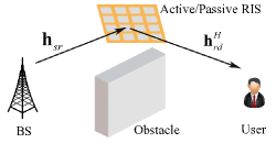
We consider a single-input single-output (SISO) system with the aid of an RIS equipped with elements as illustrated in Fig. 1. The BS-RIS and RIS-user channels are denoted by and , respectively. For the sake of comparison, we assume that the direct channel is blocked due to obstacles.
As in [9, 8], we assume that line-of-sight (LoS) paths exist in RIS-reflected channels. Based on the uniform linear array (ULA) model, we denote that and , where and are the angles of arrival and departure, respectively. and represent the distance-dependent path-loss factors expressed as and , where represents the reference strength for the channel at a distance of m, and are distances, and and denote the path-loss exponents. Note that it is general to set dB and . Accordingly, for moderate distances of m and path exponents of , the channel gains would be dB, which are very small values. Without amplification, the received signal at the user suffers from the product/double path-loss dB and therefore becomes very weak. In the sequel of this letter, the order of magnitude of and could help us better understand the performance comparison between the active RIS and the passive RIS.
Define the reflection matrix of the RIS as , where denotes the phase shift of the -th RIS reflecting element. For passive RIS, we have . However, are feasible for active RIS due to its amplifiers. For simplicity, we assume that and then define . Let denote the symbol transmitted from the BS. Then, the signal reflected by the active RIS and finally received by the user is given by
| (1) |
where is the transmit power of BS in active RIS systems, denotes the thermal noise introduced by active RIS components, and represents the thermal noise at the receiver. Letting and , we can obtain the received signal in the passive RIS-aided system as follows
| (2) |
where is the transmit power of BS in passive RIS systems. Besides, the overall power consumption of active and passive RIS-aided systems are respectively given by[8]
| (3) |
where is the output signal power of active RIS, is the power consumed by the phase shift switch and control circuit in each RIS elements, is the direct current biasing power used by each active RIS element.
III Active RIS versus Passive RIS
Based on (1), the achievable rate of active RIS systems is , in which the signal-to-noise-ratio (SNR) is expressed as
| (4) |
where utilizes the optimal design of , i.e., .
Substituting (III) with and , we obtain the achievable rate of passive RIS systems as , where
| (5) |
Comparing (III) with (5), it is obvious that , if (without the same power budget constraint), (for dB), , and . Therefore, for a fair comparison, it is necessary to constrain that both two schemes have the same overall power budget , which means . In this context, the superiority of active RIS over passive RIS is non-trivial and needs to be re-examined again.
III-A Problem Formulation with the Same Power Budget
Assume that the total power budget is , i.e., . From (3), we have
| (6) | |||
| (7) |
where corresponds to the available power left for allocating to the BS and active RIS after supplying the hardware power consumption. Clearly, if , we have and . Therefore, we only focus on the region of in this section.
Different from the passive RIS, we need to additionally decide the optimal power allocation for and given . The optimization problem is formulated as
| (8a) | ||||
| (8b) | ||||
| (8c) | ||||
Since increases with , substituting (8c) into (8b), the optimal should satisfy the following condition
| (9) |
Then, the original problem is transformed to
| (10a) | ||||
| (10b) | ||||
It is readily to find and . Therefore, it is necessary to decide the optimal power allocation between the BS and the active RIS.
III-B Optimal Power Allocation
Theorem 1.
If , the optimal power allocated to the BS is . Otherwise, we have
| (11) |
Meanwhile, the optimal power allocated to the RIS is .
Proof: Please refer to Appendix A.
If , condition can be satisfied when the RIS is located in the middle between the BS and the user. In this special case, it is optimal to equally allocate the power to the BS and the RIS. Unless otherwise stated, we focus on the case in the following.
Corollary 1.
When , and . When , , which further tends to if .
As , the receiver noise becomes dominant, and therefore larger is preferred, which achieves larger and then reduces the term in (III). As , the RIS noise becomes dominant, and it is useless to increase since it also amplifies the RIS noise term in (III). In this case, increasing can effectively improve the SNR.
Corollary 2.
Both and are increasing functions of but decreasing functions of .
Proof: Please refer to Appendix B.
Corollary 2 shows that as power budget grows, it is optimal to simultaneously increase the power of the BS and the RIS. Fully allocating the increased power to the BS/RIS unfairly will sacrifice the performance. Meanwhile, when increases, less power is left for the BS and the RIS, and it is optimal to simultaneously cut down their power.
Corollary 3.
When , is an increasing function of but decreasing function of . On the contrary, when , is a decreasing function of but increasing function of .
Proof: Please refer to Appendix C.
Although the power should be allocated fairly, Corollary 3 unveils that there do exist some allocation priorities for increased . With larger , more power should be allocated to the BS, since reduces the impact of RIS noise. By contrast, with larger , more power should be allocated to the active RIS, which leads to larger and therefore decreases the impact of receiver noise. Besides, by moving the RIS closer to the user, increases while decreases. Hence, when the RIS is located near the BS (user), more power should be allocated to the RIS (BS). This is because the received signal at the RIS is stronger with larger , and larger is needed to amplify a stronger signal for a certain multiple as shown in (9).
III-C SNR Comparison
Lemma 1.
Passive RIS performs better if
| (12) |
Otherwise, active RIS performs better when
| (13) |
We firstly focus on condition (12). Since , passive RIS must be better if , i.e., for sufficiently large , since in this case active RIS suffers from severe noise . (12) is easier to hold for small or large . This is because active RIS can effectively mitigate the impact of but it is impaired by . If , condition (12) is equal to , which means that the attenuation from path-loss is compensated by RIS’s gain and therefore double path-loss attenuation no longer exists. However, we emphasize that the satisfying condition (12) may be very large due to the small value of .
Lemma 2.
Define . If , increases with . If , depending on the values of , could be an increasing function or a function which firstly increases but then decreases with . In addition, and which approaches as .
Proof: Please refer to Appendix D.
Corollary 4.
Passive RIS outperforms active RIS for small , i.e., for low power budget .
Proof: Define . If , condition (12) holds for all (also for small ). If not, from Lemma 2, there exists an intersection point so that . Then, condition (12) holds for all .
The above discussions demonstrate that passive RIS is better for very large and very small . We next use condition (13) to demonstrate the superiority of active RIS when is not very large and is not very small.
Corollary 5.
Active RIS outperforms passive RIS if , , and .
IV Simulation Results
We consider the same simulation setup as in [8, 7]. If not specified otherwise, we set , dBm, dBm, dBm, and dBm. For the path-loss factors, we set dB, . The BS and the user are located at and , respectively. The RIS is located at where m is adopted by default.
We first validate our conclusion in Corollary 5. Based on the above simulation setup and use the sub-optimal solution , we can calculate the left- and right-hand side of (13) as and , respectively, which verifies the correctness of Corollary 5.
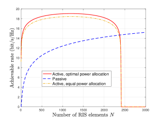
Fig. 2 illustrates the superiority of active RIS when is not very large. This is because active RIS can exploit a small amount of power to amplify the signal attenuated after the transmission in the first hop, and therefore significantly improve the strength of the signal received at the user. When is very large, passive RIS becomes superior while the data rate of active RIS begins to decrease. This is because a huge amount of power is consumed by active RIS to supply its amplifiers and also because of the stronger active RIS thermal noise . To sum up, active RIS is more promising than passive RIS since it can achieve a high achievable rate with a small number of elements.
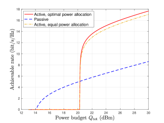
Being consistent with Corollaries 4 and 5, Fig. 3 unveils that the passive RIS performs better for small power budgets while the active RIS is superior when the power budget is sufficient. Meanwhile, it can be seen that the equal allocation strategy begins to show its defects as increases. This is because as the power budget grows, the optimal allocation ratio between the BS and active RIS needs to be adjusted accordingly, as discussed in Corollary 3.
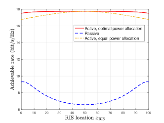
Finally, Fig. 4 compares the active and passive RISs for different deployments. It is shown that active RIS can perform constantly better in all deployments. It is known that the passive RIS should be deployed near the BS or the user in order to alleviate the attenuation from double path-loss. However, the active RIS can be deployed flexibly since the double-fading effect is effectively circumvented thanks to the integration of amplifiers. Besides, compared to the equal power allocation scheme which only achieves optimality for a middle deployment, the proposed optimal allocation scheme can dynamically balance the power allocation and then make the achievable rate of active RIS stable in all locations.
V Conclusion
This letter theoretically compared the active RIS with the passive RIS under the same power budget. We firstly derived the optimal power allocation ratio between the BS and the active RIS. We then provided some insights based on the derived allocation ratio and discussed the conditions when active or passive RIS performs better.
Appendix A
The first-order derivative of in (10a) with respect to is given by
| (16) |
where
| (17) |
If , is a linear function with . Clearly, the optimal solution is . When , is a quadratic function with and . Therefore, there must exist one and only one root for within . When , . When , . Accordingly, based on (16), is maximized at . We next derive the root which locates in . After some simplifications, two roots of are given by
| (18) |
Appendix B
The first-order derivative of with respect to is
| (19) |
where and
| (20) |
where utilizes the inequality and as assumed before. Therefore, the function in (19) monotonously increases (decreases) with if (). Besides, we have and . Due to the monotonicity, there must be . Similarly, using , we can prove . Since increases with but decreases with , the proof is completed.
Appendix C
Define . Then, we have
| (21) |
and . Note that we have proved that is a decreasing function. When , is an increasing function leading to for . When , is a decreasing function leading to for .
Appendix D
Using , we have where with . Besides, we have . As proved in Appendix B, if , which leads to and . By contrast, if , we have and then is a decreasing function. As , we have
| (22) |
where the first term is negative while the second term is positive. Thus, when is larger than a threshold, and then . Otherwise, decreases from positive value to negative value which means that firstly increases but then decreases.
References
- [1] M. Di Renzo, A. Zappone, M. Debbah, M. S. Alouini, C. Yuen, J. de Rosny, and S. Tretyakov, “Smart radio environments empowered by reconfigurable intelligent surfaces: How it works, state of research, and the road ahead,” IEEE J. Sel. Areas Commun., vol. 38, no. 11, pp. 2450–2525, Nov. 2020.
- [2] Q. Wu and R. Zhang, “Intelligent reflecting surface enhanced wireless network via joint active and passive beamforming,” IEEE Trans. Wireless Commun., vol. 18, no. 11, pp. 5394–5409, Nov. 2019.
- [3] C. Pan, H. Ren, K. Wang, M. Elkashlan, A. Nallanathan, J. Wang, and L. Hanzo, “Intelligent reflecting surface aided MIMO broadcasting for simultaneous wireless information and power transfer,” IEEE J. Sel. Areas Commun., vol. 38, no. 8, pp. 1719–1734, Aug. 2020.
- [4] C. Huang, A. Zappone, G. C. Alexandropoulos, M. Debbah, and C. Yuen, “Reconfigurable intelligent surfaces for energy efficiency in wireless communication,” IEEE Trans. Wireless Commun., vol. 18, no. 8, pp. 4157–4170, Aug. 2019.
- [5] C. Pan et al., “Multicell MIMO communications relying on intelligent reflecting surfaces,” IEEE Trans. Wireless Commun., vol. 19, no. 8, pp. 5218–5233, Aug. 2020.
- [6] E. Björnson, Ö. Özdogan, and E. G. Larsson, “Intelligent reflecting surface versus decode-and-forward: How large surfaces are needed to beat relaying?” IEEE Wireless Commun. Lett., vol. 9, no. 2, pp. 244–248, Feb. 2020.
- [7] Z. Zhang, L. Dai, X. Chen, C. Liu, F. Yang, R. Schober, and H. V. Poor, “Active RIS vs. passive RIS: Which will prevail in 6G?” 2021. [Online]. Available: https://arxiv.org/abs/2103.15154
- [8] R. Long, Y.-C. Liang, Y. Pei, and E. G. Larsson, “Active reconfigurable intelligent surface aided wireless communications,” IEEE Trans. Wireless Commun., vol. 20, no. 8, pp. 4962–4975, Aug. 2021.
- [9] C. You and R. Zhang, “Wireless communication aided by intelligent reflecting surface: Active or passive?” IEEE Wireless Commun. Lett., early access, 2021.
- [10] M. H. Khoshafa, T. M. N. Ngatched, M. H. Ahmed, and A. R. Ndjiongue, “Active reconfigurable intelligent surfaces-aided wireless communication system,” IEEE Commun. Lett., vol. 25, no. 11, pp. 3699–3703, Nov. 2021.
- [11] K. Liu, Z. Zhang, L. Dai, S. Xu, and F. Yang, “Active reconfigurable intelligent surface: Fully-connected or sub-connected?” IEEE Commun. Lett., early access, 2021.
- [12] P. Zeng, D. Qiao, Q. Wu, and Y. Wu, “Active IRS aided WPCNs: A new paradigm towards higher efficiency and wider coverage,” 2021. [Online]. Available: https://arxiv.org/abs/2111.11600
- [13] D. Xu, X. Yu, D. W. K. Ng, and R. Schober, “Resource allocation for active IRS-assisted multiuser communication systems,” 2021. [Online]. Available: https://arxiv.org/abs/2108.13033