Performance evaluation of the QOS provisioning ability of IEEE 802.11e WLAN standard for multimedia traffic
Abstract
This paper presents an analytical model for the average frame transmission delay and the jitter for the different Access Categories (ACs) of the IEEE 802.11e Enhanced Distributed Channel Access (EDCA) mechanism. Following are the salient features of our model. As defined by the standard we consider (1) the virtual collisions among different ACs inside each EDCA station in addition to external collisions. (2) the effect of priority parameters, such as minimum and maximum values of Contention Window (CW) sizes, Arbitration Inter Frame Space (AIFS). (3) the role of Transmission Opportunity (TXOP) of different ACs. (4) the finite number of retrials a packet experiences before being dropped. Our model and analytical results provide an in depth understanding of the EDCA mechanism and the effect of Quality of Service (QoS) parameters in performance of IEEE 802.11e protocol.
Index Terms:
Wireless LAN, IEEE 802.11e, EDCA, Markov chain model, Performance analysis, Delay, Jitter.I Introduction
The IEEE 802.11 standard and many of its enhancements like a, b, e, g, n, ad are some of the most widely deployed Wireless Local Area Network (WLAN) standards [1]. These days IEEE 802.11 WLAN based hotspots are available at offices, university campuses, airports, hotels, residential areas etc. enabling people to get connected to the Internet easily. The WLAN can be set up in a simple manner in almost all areas without requiring the use of extensive infrastructure.
The IEEE 802.11 WLAN defines two architectures namely Basic Service Set (BSS) and Independent Basic Service Set (IBSS). In BSS all wireless nodes are connected to an access point (A.P.) and communicate only through that A.P. In (IBSS) nodes communicate directly with each other in an adhoc manner i.e without an A.P.
IEEE 802.11 MAC defines two different mechanisms for frame transmission namely Distributed Coordination Function (DCF) and Point Coordination Function (PCF). DCF uses Carrier Sense Multiple Access with Collision Avoidance (CSMA/CA) mechanism with slotted Binary Exponential Back-off (BEB) algorithm. PCF provides controlled channel access through polling.
Today’s WLAN carry many forms of media such as video, voice, data and signaling. Information services on the Internet come in varying forms, such as web browsing, e-mail, VOIP based telephony and multimedia on demand. This means that different applications have different service features and desired QoS. Multimedia applications such as VOIP, and video-on demand have stringent QOS requirements and are sensitive to delay and jitter in their traffic. In contrast web-browsing are bursty in nature and do not require QOS service guarantee on delay and jitter. While multimedia traffic can tolerate packet loss, applications like FTP needs to be very reliable.
In the IEEE 802.11 standard, there is no traffic differentiation. In view of this an enhanced Channel access mechanism has been introduced in the IEEE 802.11e standard to satisfy the QoS requirements of different traffic. The EDCA mechanism has also been implemented in ieee 802.11p vehicular Networks [2] to maintain traffic priorities.
In this work we carry out the performance analysis of IEEE 802.11e standard to bring out its ability to provide QoS for the multimedia traffic. To this end we first give an overview of the IEEE 802.11 and 802.11e MAC protocol followed by the literature survey before doing the analysis.
I-A Overview of IEEE 802.11 and 802.11e MAC Protocol

The IEEE 802.11 DCF operates in two modes. First mechanism is the basic access mechanism and the second mechanism is by using RTS/CTS frames. Figure 1 illustrates the basic access mechanism. In basic access mechanism a station with a new frame to transmit, continuously monitors the channel activity. If the channel is sensed to be idle for a period equal to at least Distributed Inter Frame Space (DIFS) time interval the station transmits. On the other hand if the channel is sensed busy, the station continuously monitors the channel activity, until the channel becomes idle for at least DIFS time. At this point the station generates a random number of slots, the random number being uniformly distributed between (0,CW-1), where "CW" denotes the contention window size.
The initial value of CW is set as W0, a value predefined by the standard. A back-off timer keeps track of the number of slots to wait for frame transmission. The back-off count value is decremented by "1" in every slot as long as the channel is idle. The counter is frozen whenever the channel is sensed busy. The countdown is reactivated when channel is again sensed idle for more than DIFS time interval. When the back-off timer count reaches zero the station attempts a transmission. If the transmitting station starts receiving ACK (acknowledgement) for a transmitted frame within SIFS time interval (defined by standards), the transmitting station assumes it as a successful frame transmission. Lack of an acknowledgement within SIFS time interval for a transmitted frame is assumed to indicate an unsuccessful frame transmission. Since SIFS time interval is less than DIFS time interval, ACK do not encounter collision. For each unsuccessful frame transmission CW is doubled until it becomes a predefined maximum value CWmax. There after CW remains constant at CWmax. According to the standards [1], a frame can have a finite number of retrials with CWmax. If collision occurs after finite retrials, the frame is dropped.
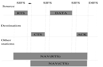
RTS/CTS mechanism is a four way hand shaking mechanism. Figure 2 illustrates the RTS/CTS mechanism wherein the source station sends a short frame called RTS before data transmission. Then the destination station responds with CTS at the end of the RTS frame after a period of time equal to SIFS, if RTS is received correctly. On the reception of CTS the sender sends the data frame to the destination within a time duration of SIFS. The successful reception of data frame is followed by an ACK frame after a period of time equal to SIFS. Successful exchange of RTS/CTS ensures that channel has been reserved for transmission for particular pair of sender and receiver.
The RTS and CTS frames carry the length of the data frame to be transmitted. All other stations hearing RTS or CTS frame update their Network Allocation Vector (NAV) containing the information of the period of time in which the channel will remain busy. Therefore other stations delay their transmission and thereby avoid interference. RTS/CTS mechanism is useful only when longer data frames are transmitted since for smaller data frame the overhead caused by using RTS/CTS would degrade the performance.
The IEEE 802.11e standard defines a new coordination function called the Hybrid Coordination Function (HCF) to support QoS. The contention based channel access mechanism of HCF is called as the Enhanced Distributed Channel Access (EDCA). The centrally controlled, contention free channel access mechanism of HCF is called the HCF controlled channel access (HCCA). The HCF combines the features of both EDCA and HCCA. We concentrate only on EDCA because HCCA is not widely used. The EDCA supports QoS by assigning different priorities for the incoming traffic.
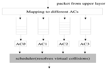
Fig.3 shows EDCA mechanism. As shown in Fig.3, each EDCA station maintains four queues for the four different Access Categories (ACs). Each frame with a particular kind of traffic is mapped to a particular AC. The service differentiation is realised by using different set of parameters for each AC. Parameters used for service differentiation are,
-
1.
AIFS (Arbitration Inter Frame Spacing): This is the time period for which medium has to be sensed idle before transmitting or initiation of backoff.
-
2.
CWmax and CWmin : These are the maximum and minimum values of contention window sizes.
-
3.
TXOP (Transmission opportunity): The maximum duration of the frame transmission after channel is accessed.
| AIFSN | TXOP | ||||
|---|---|---|---|---|---|
| 0 | AC0 | 7 | 15 | 2 | 3.264ms |
| 1 | AC1 | 15 | 31 | 2 | 6.016ms |
| 2 | AC2 | 31 | 1023 | 3 | 0 |
| 3 | AC3 | 31 | 1023 | 7 | 0 |
(IEEE 802.11e standard [1])
As shown in the table I, the high priority AC (i.e AC0) has smaller values of AIFS, CWmin, CWmax, and larger value of TXOP compared to low priority AC (i.e AC3). There are two types of collisions that are present in EDCA. They are internal collisions (also called as virtual collisions) and external collisions. Virtual collision occurs because two or more ACs within a station attempt to transmit in the same slot ( i.e , decrease their back-off counter to zero simultaneously). When virtual collision occurs transmission opportunity is given to the highest priority AC and the lower ACs behave as if an external collision has occurred and follows the back-off rules. The scheduler resolves the internal collisions by assigning transmission opportunity to the highest AC involved in collision.
I-B Literature Survey
Many analytical models for DCF have been proposed in the literature [3], [4], [5], [6], [7], [8], [9], which are relevant to our work. Bianchi [3], proposed a two dimensional markov chain model and calculated the saturation throughput for IEEE 802.11 DCF. Assumptions made by Bianchi were (i) constant and independent collision probability for each transmitting frame, and (ii) ideal channel conditions. Most of the authors in the literature use the markov chain similar to the Bianchi’s markov chain.
Xiao [10] extended the Bianchi’s Markov Chain model to priority schemes and compared these priority schemes with DCF. But the concept of virtual collision was not considered. Tao [11] proposed a three dimensional Markov Chain for IEEE 802.11e EDCA mechanism and calculated the throughput analytically for each access categories of EDCA. Zheng [12] proposed a Markov Chain for DCF under saturated traffic conditions and calculated the throughput by considering the concept of virtual collision and different AIFS parameter values. Yin [13] analysed protocol service time of EDCA under statistical traffic using Markov Chain model. Throughput and average frame transmission delay have been calculated under statistical traffic conditions.
Liu [14] calculated the performance of EDCA under unsaturated traffic conditions. Throughput and average frame transmission delay are calculated analytically using a four state Markov Chain. Tinnirello et al. have modeled 802.11e EDCA that relies on decoupling approximation and performs fixed point computation of the backoff counter distribution after a generic transmission attempt [15]. MacKenzie et al. have modelled 802.11e as p-persistent CSMA where the access probability can be varied for different access categories using the differentiation of CW, AIFS etc. [16]. Qinglin et al. have considered an unsaturated 802.11e network and models joint differentiation of all four EDCA parameters for arbitrary buffer size, using M/G/1/K queuing model [17].
Abu et al. have studied the performance of 802.11e EDCA under finite load and error prone channel, using a multidimensional Markov chain along with another Markov model for channel [18]. Ramaiyan et al. have performed a fixed point analysis of 802.11e WLAN and shown the presence of multistability when multiple unbalanced fixed point exist [19]. Inan et al. considered the analysis of the 802.11e EDCA function using a DTMC model [20].
In most of the papers mentioned above throughput and average frame transmission delay were calculated for different access categories without considering the concept of internal collisions. Some models do not consider the effect of TXOP on the QoS-differentiation. Further there is a need for analyzing jitter which is an important QoS metric. Our model differs from existing models in the following ways :
-
1.
As defined by the standards we consider the virtual collisions among different ACs inside each EDCA station in addition to external collisions.
-
2.
In our model we consider the effect of all the priority parameters such as CWmax, CWmin, AIFS, TXOP and finite number of retrials.
-
3.
Average frame transmission delay as well as jitter of all ACs are derived analytically.
This paper is organized as follows. Section II describes our modified Bianchi’s Markov chain model of a DCF station valid for any one category. We derive an analytical formula for probability of transmission of a frame in any generic time slot. Then we extend our analytical results which we get in the section II to EDCA mechanism in section III. In the section IV, we derive an analytical formula for the average frame transmission delay. In the section V we analyse jitter for different ACs of an EDCA station. In the section VI, we analyse our results based on numerical computation. Finally, our conclusions are given in the section VII.
II Modified Bianchi’s Markov Chain Model for DCF
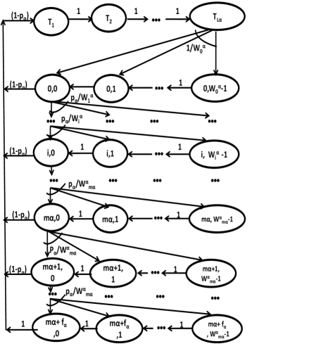
In this section we introduce and analyze a modified Bianchi’s markov chain model shown in the fig. 4. Assumptions made are (i) constant and independent collision probability for each transmitted frame, and (ii) ideal channel conditions. We use the index to denote the access category (AC), where = 0,1,2,3. We assume that each of the ACs can be modeled as Markov chain shown in the Fig. 4.
Let be the of the AC number . Let 111We have used the symbol and not to denote the maximum number of stages in , since itself appear as subscript in certain places. denote the number of stages for the . Let denote the number of retrials permitted for after stages. Let denote the number of data packets that can be transmitted with in the TXOP period by the .
Following is the explanation of the Markov Chain model shown in the Fig. 4. In the Fig. 4, the state at any given slot corresponds to back-off stage and with a value of back-off counter as . The values of for denoted as are given in table I. The size of the collision window for the stage (reached after collisions) belonging to denoted as is given by . The variable ranges from to , where is the maximum retransmission limit after which if collision occurs the frame is dropped. Here is the maximum number of stages up to which back-off counter doubles, = , is the maximum number of retrials after stage . The index ranges from to . The station enters the stage from the stage when the transmitted frame encounters a collision.
The bidimensional process is Markovian [3]. We adopt the following discrete time scale. Let and corresponds to the beginning of two consecutive time slots. The back-off counter is decremented at the beginning of each idle slot. This implies that between two state transitions there can either be no packet transmission or one successful packet transmission or collision. The back-off counter decrementation is stopped when the channel is busy. So, the time interval between two successive counter decrementation varies depending on the channel condition.
We use the following short hand notation for one step state transition probability:
Let be the stationary state occupancy probability of Markov Chain for the . A station transmits a frame when back-off counter value is equal to zero. If the transmission is successful the node continues to transmit its packet from the for a duration equal to TXOP corresponding to . This is indicated by a sequence of states called transmitting states denoted as T1,T2,… . The values of TXOP for different ACs are shown in table I. Let denote the number of packets that can be transmitted by in its TXOP. = , where is the floor function. For AC2 and AC3 the standard indicates the value of TXOP as ’0’ (refer table I). This implies that only one packet transmission is permissible in its TXOP. In other words .
Let "" be the constant conditional collision probability which is derived later in the Eqn. 14. The non-null one step state transition probabilities for the above Markov Chain can be derived along the lines similar to that of Bianchi [3],
-
1.
After successful transmission of frames in its TXOP the station enters into the state where
In the above equation, for , . This is because in saturated traffic conditions, station always has frames ready for transmission. In the state, there are only two possible conditions. They are successful frame transmission after which station enters into the stage "", with probability "" or dropping of the frame with probability "". In either case station enters into the stage "".
-
2.
During the TXOP period packets are transmitted one after another until packets get transmitted.
(1) Followed by this, the backoff process is initiated by setting the counter to a random value following the distribution . Recall that for and .
-
3.
Stage changes from to when a transmitted frame encounters collision.
-
4.
Back-off time counter is decremented by "1" in each slot.
The effect of freezing the back-off counter (for busy channel conditions) is considered later in the section III.
In the steady state the following equations can be derived along the lines similar to that of Bianchi [3]:
The expression for is given by,
| (2) |
From the inspection of Markov chain, the expression for can be written as,
| (3) |
Now we derive an expression for in terms of "". From the probability conservation formula[21],
| (4) |
substituting Eqns. 2, 3 in Eqn.4 and noting that = and = to we get,
| (5) |
From the Eqn.II, after some algebra we get an expression for given by the Eqn.8.
Now we derive an analytical formuale for probability of transmission of a frame in any generic time slot "". Since a frame will be transmitted when the counter value is equal to zero, the expression for "" is given by the equation,
| (6) |
Where is the state occupancy probability of a station in a generic stage "i". The expression for is given by the Eqn. 2.
III Analysis of IEEE 802.11e EDCA with virtual collisions
In this section we extend the results which we got in the section II to EDCA mechanism by considering the concept of virtual collisions. We derive an analytical expression for probability of transmission of a frame in any generic time slot for an EDCA station.
As shown in the Fig. 3, EDCA maintains four different ACs. Each of the ACs has different QoS parameters. Each AC contends for the channel with different values of AIFS and different sizes of and . Let be the value of AIFS for an AC "". According to the standards the value of where "" is Arbitrary Inter Frame Space Number which is different for different AC. The values of AIFSN for four ACs are given in the table I.
When virtual collision occurs within an EDCA station, transmission opportunity is given to the highest colliding AC, and lower AC differ their transmission and follow the back-off rules. Let and be the probabilities of transmission of a frame from AC0, AC1, AC2 and AC3 respectively as given by Eq.7 for . The probability of transmission of a frame by an EDCA station from any AC in any generic time slot "" is given by Eqn.9.
| (8) |
| (9) |
Now let us derive an expression for probability of collision of a frame from an ACα. Let represents the probability of internal collision for a frame from an ACα.
-
1.
Internal collision will not occur for a frame which has been transmitted from AC0.
(10) -
2.
Internal collision for a frame in AC1 will happen only when a frame from AC0 transmits in the same slot.
(11) -
3.
Internal collision for AC2 will happen when a frame from any one of the AC0 or AC1 transmits in the same slot.
(12) -
4.
Internal collision for AC3 will happen when a frame from any one of the AC0 or AC1 or AC2 transmits in the same slot.
(13)
The probability of collision for ACα, is given by,
| (14) |
Where Pex is the probability that the transmitted frame encounters an external collision which is same for all stations. The expression for Pex is given by the equation,
| (15) |
We now derive PSα the conditional probability that the frame transmitted from the ACα is successful given that a frame is transmitted by a station.
-
1.
Let PS0 be the conditional probability that the frame transmitted from AC0 is successful given that a frame is transmitted by a station. This is possible when no other station transmits in the same slot. The expression for PS0 is given by,
(16) -
2.
Let PS1 is the conditional probability that a frame transmitted from AC1 is successful given that a frame is transmitted by the station. This is possible when (i) a packet from AC0 of the same station is not transmitted in the same slot and (ii) no other station transmits in the same slot. The expression for PS1 is given by,
(17) -
3.
Let PS2 be the conditional probability that the transmission of frame from AC2 is successful. This is possible when (i) a frame from either AC0, AC1 belonging the same station is not transmitted in the same slot and (ii) no other station transmits in the same slot. The expression for PS2 is given by,
(18) -
4.
Let PS3 be the conditional probability that the transmission of the frame from AC3 is successful. This is possible when (i) a frame from either AC0, AC1, AC2 belonging the same station is not transmitted in the same slot and (ii) no other station is transmitted in the same slot. The expression for PS3 is given by,
(19)
From the simultaneous non-linear Eqns. from 7 to 15 by using numerical methods we can find the value of probability of transmission of a frame in any generic slot "" for a given EDCA station.
IV Average frame transmission delay analysis
In this section, we derive an analytical expression for average frame transmission delay for different ACs of an EDCA station.
Let "" be the number of states visited by a station for successful packet transmission from an (i.e, number of back-off counter decrements for successful packet transmission). The expected number of slots visited by a station belonging an ACα, in the stage is , where is then . One extra slot accounts for the frame transmission.
| (20) |
where is the probability that transmission is successful in the stage for an , given that the frame is not dropped. The term in equation 20 accounts for the number of slots spent in the TXOP period. is different for different ACs because, is a function of minimum and maximum values of contention window, and which is different for different ACs.
IV-A Derivation of expected time duration of the state transition for ACα:
Let T be the time the channel is sensed busy because of successful frame transmission, and T be the time the channel is sensed busy by each station because of collision for a frame from an ACα. For the basic access mechanism, value of T for an ACα is given by the equation,
| (21) |
Where t is the time required for frame transmission which is calculated as where "R" is data rate and Lp is the payload size . tH the time required for transmission of both PHY and MAC headers which is given by where "H" is equal to sum of MAC header and PHY header in bits. In the above equation tACK is equal to where LACK is length of ACK frame.
The value of T for basic access mechanism is given by the equation,
| (22) |
The value of T for RTS/CTS mechanism is given by,
| (23) | |||||
and the value of T for RTS/CTS is given by the equation,
| (24) |
Let E(Tα) be the expected time duration of the state transition for ACα. The channel may be idle or busy. The duration of the state transition is with the probability if the channel is busy because of successful frame transmission. The value of for and given by equations 16 to 19. The duration is equal to with probability if the channel is busy because of collision for corresponding AC "". If the channel is idle then station takes to decrement its back-off count. The expression for is given by the Eqn. 26. Here is the probability of a transmission in a given slot and is given by . The final term indicates how many extra time slots the station has to wait after the channel is sensed idle in order to decrement the back-off counter value. Numerically it is equal to the number of slots in the DIFS time interval. According to the standards .
From the table I, AIFSN values for AC0 and AC1 is equal to 2, for AC2 has a value of 3 and AC3 has a value of 7. So, AC0 and AC1 decrement the back-off count value by one if the channel is idle for DIFS time interval. AC3 has to wait for an one slot extra to decrement its back-off count and AC3 has to wait 5 more slot times to decrement its back-off count as compared to AC0 and AC1.
Note that every time a transmission attempt become successful packets will be transmitted in the TXOP by . Thus the channel access delay "" for one packet belonging to is given by,
| (25) |
| (26) |
From the Eqn. 25, the expected frame transmission delay for an , "" is given by,
| (27) |
V Jitter Analysis
The Jitter is defined as the square root of variance in the delay. , . Let Var(Dα) represents the variance in the delay for an access category "". Let denote the variance of number of states visited by a frame from an for a given station for successful frame transmission.
From equation 25 treating and to be constants we get[21],
| (28) |
is given in the Eqn. 26. is given by the Eqn. 31. From the Eqn.28 we can find the jitter for is given by
| (29) |
Expression for expected frame transmission delay of an AC of an EDCA station is given by:
| (30) |
Expression for Variance of frame transmission delay:
| (31) |
VI Numerical Result
In this section we present our analytical results computed numerically using the Mathematica package [22].
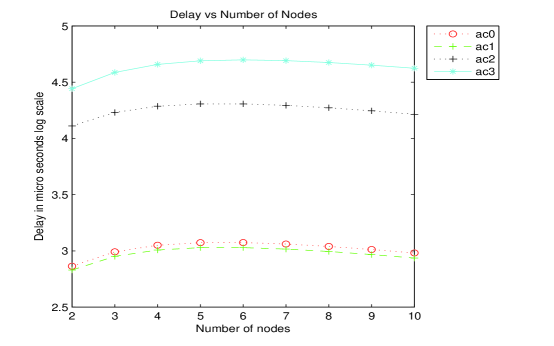
Fig. 5 shows the delay computed numerically using equations (26), (27), (V) for different access categories. From Fig. 5 it can be seen that the delay of access categories and are considerably less than that of and . Notice from Table I that the values of and of and are much lower as compared to and (31 - 1023). This ensures that the expected value of the counter at any given is less for and as compared to and . Further lower values of implies that and has to wait for lesser number of slots to restart the backoff process once the channel becomes free. Further larger values for followed by allows a number of packets to be transmitted after each successful contention which reduces the contention overhead. All these factors along with the concept of internal collision contributes to the lower values of delay for and . The differentiating factor between and are and the internal collision which explains the larger value of delay as compared to .
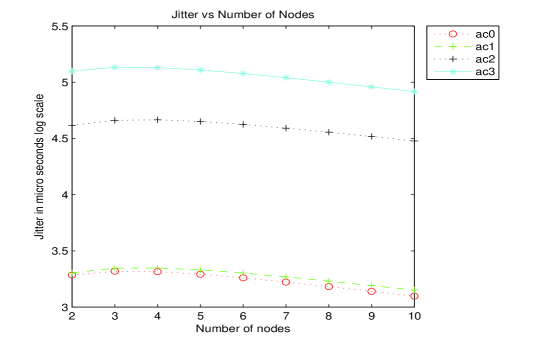
Fig. 6 shows the jitter computed numerically using equations (26), (28), (31). Fig. 6 shows that the jitter of access categories and are considerably less than that of and . The arguments mentioned above explaining lower values of delay for and as compared to and also hold good for jitter. Both delay and jitter do not vary much with the number of nodes as nodes are assumed to be saturated.
VII Conclusion
In this paper we have presented the performance of IEEE 802.11e EDCA standard under saturated and ideal channel conditions. We have derived the analytical formulae for the average frame transmission delay and jitter for different access categories of EDCA station. In our model, as defined by the standards we have considered the internal collisions which may occur within an EDCA station, as well as external collisions which may occur among the EDCA stations. The effect of priority parameters such as CWmin, CWmax sizes, AIFS values, and finite retrials on packet transmission delay and Jitter for an EDCA station under saturated traffic conditions have been analysed. Our analytical results quantifies the goal of the IEEE 802.11e standard to provide QOS for high priority multimedia traffic.
References
- [1] “Ieee standard for information technology–telecommunications and information exchange between systems local and metropolitan area networks–specific requirements part 11: Wireless lan medium access control (mac) and physical layer (phy) specifications - redline,” IEEE Std 802.11-2012 (Revision of IEEE Std 802.11-2007) - Redline, pp. 1–5229, 2012.
- [2] “Ieee standard for wireless access in vehicular environments (wave)–multi-channel operation,” IEEE Std 1609.4-2010 (Revision of IEEE Std 1609.4-2006), pp. 1–89, Feb 2011.
- [3] G. Bianchi, “Performance analysis of the IEEE 802.11 distributed coordination function,” Selected Areas in Communications, IEEE Journal on, vol. 18, no. 3, pp. 535–547, 2000.
- [4] E. Ziouva and T. Antonakopoulos, “Csma/ca performance under high traffic conditions: throughput and delay analysis,” Computer Communications, vol. 25, no. 3, pp. 313–321, 2002.
- [5] C. Wang, B. Li, and L. Li, “A new collision resolution mechanism to enhance the performance of IEEE 802.11 DCF,” Vehicular Technology, IEEE Transactions on, vol. 53, no. 4, pp. 1235–1246, 2004.
- [6] T. Sakurai and H. Vu, “MAC access delay of IEEE 802.11 DCF,” Wireless Communications, IEEE Transactions on, vol. 6, no. 5, pp. 1702–1710, 2007.
- [7] O. Tickoo and B. Sikdar, “A queueing model for finite load IEEE 802.11 random access MAC,” in Communications, 2004 IEEE International Conference on, vol. 1. IEEE, 2004, pp. 175–179.
- [8] P. Raptis, V. Vitsas, P. Chatzimisios, and K. Paparrizos, “Delay jitter analysis of 802.11 DCF,” Electronics Letters, vol. 43, no. 25, pp. 1472–1474, 2007.
- [9] A. Babu and L. Jacob, “Fairness analysis of IEEE 802.11 multirate wireless LANs,” Vehicular Technology, IEEE Transactions on, vol. 56, no. 5, pp. 3073–3088, 2007.
- [10] Y. Xiao, “Performance analysis of priority schemes for IEEE 802.11 and IEEE 802.11 e wireless LANs,” Wireless Communications, IEEE Transactions on, vol. 4, no. 4, pp. 1506–1515, 2005.
- [11] Z. Tao and S. Panwar, “Throughput and delay analysis for the IEEE 802.11 e enhanced distributed channel access,” Communications, IEEE Transactions on, vol. 54, no. 4, pp. 596–603, 2006.
- [12] Z. Kong, D. Tsang, B. Bensaou, and D. Gao, “Performance analysis of IEEE 802.11 e contention-based channel access,” Selected Areas in Communications, IEEE Journal on, vol. 22, no. 10, pp. 2095–2106, 2004.
- [13] J. Tantra, C. Foh, I. Tinnirello, and G. Bianchi, “Analysis of the IEEE 802.11 e EDCA under Statistical Traffic,” in Communications, 2006. ICC’06. IEEE International Conference on, vol. 2. IEEE, 2006, pp. 546–551.
- [14] J. Liu and Z. Niu, “Delay analysis of IEEE 802.11 e EDCA under unsaturated conditions,” in Wireless Communications and Networking Conference, 2007. WCNC 2007. IEEE. IEEE, 2007, pp. 430–434.
- [15] I. Tinnirello and G. Bianchi, “Rethinking the ieee 802.11e edca performance modeling methodology,” Networking, IEEE/ACM Transactions on, vol. 18, no. 2, pp. 540–553, 2010.
- [16] R. MacKenzie and T. O’Farrell, “Achieving service differentiation in ieee 802.11e enhanced distributed channel access systems,” Communications, IET, vol. 6, no. 7, pp. 740–750, 2012.
- [17] Q. Zhao, D. Tsang, and T. Sakurai, “A scalable and accurate nonsaturated ieee 802.11e edca model for an arbitrary buffer size,” Mobile Computing, IEEE Transactions on, vol. 12, no. 12, pp. 2455–2469, 2013.
- [18] O. Abu-Sharkh and A. Tewfik, “Toward accurate modeling of the ieee 802.11e edca under finite load and error-prone channel,” Wireless Communications, IEEE Transactions on, vol. 7, no. 7, pp. 2560–2570, 2008.
- [19] V. Ramaiyan, A. Kumar, and E. Altman, “Fixed point analysis of single cell ieee 802.11e wlans: Uniqueness and multistability,” Networking, IEEE/ACM Transactions on, vol. 16, no. 5, pp. 1080–1093, 2008.
- [20] I. Inan, F. Keceli, and E. Ayanoglu, “Analysis of the 802.11e enhanced distributed channel access function,” Communications, IEEE Transactions on, vol. 57, no. 6, pp. 1753–1764, 2009.
- [21] S. M. Ross, Introduction to probability models. Academic press, 2014.
- [22] Wolfram Research, Inc., Mathematica, Version 10.0, Champaign, IL, 2014.