Flat Magic Window
Abstract
Magic windows (or mirrors) consist of optical devices with a surface deformation or thickness distribution devised in such a way to form a desired image. The associated image intensity distribution has been shown to be related to the Laplacian of the height of the surface relief. We experimentally realize such devices with flat optics employing optical spin-to-orbital angular momentum coupling, which represent a new paradigm for light manipulation. The desired pattern and experimental specifications for designing the flat optics was implemented with a re-configurable spatial light modulator which acted as the magic mirror. The flat plate, optical spin-to-orbital angular momentum coupler, is then fabricated by spatially structuring nematic liquid crystals. The plate is used to demonstrate the concept of a polarization-switchable magic window, where, depending on the input circular polarization handedness, one can display either the desired image or the image resulting from the negative of the window’s phase.
The mechanism behind ancient magic mirrors from China and Japan was not understood until the 20th century, despite the earliest creations of these artistic pieces dating back to 2000 BC berry2005oriental . The cast bronze mirrors presented as normal mirrors while viewing ones reflection. However, when sunlight was shone directly on the mirror, it acted as a subtly parabolic mirror forming an image—corresponding to patterning on the back side of the mirror—presented on the floor or a screen ayrton1879ii . A similar phenomenon can be observed in the reflection of the sun off large windows and onto a street below. Though the window appears flat and does not significantly distort an image while we look through it, the slight deformations from tension around the edges result in a non-uniform reflection onto the ground in the shape of an “X”-pattern. Despite deriving from a millennia old tradition, magic mirrors inspired a measurement technique (called Makyoh topography after the Japanese word for “wonder mirror”) for detecting surface deformities in silicon wafers in the late 20th century kugimiya1990characterization ; laczik2000quantitative . This approach has the advantage of being very simple and practical for industry based applications, in comparison with other measurement techniques such as interferometry or atomic force microscopy kugimiya1988characterization .
The mathematical description and final understanding of how the magic mirrors worked was derived in 2005 by Sir Michael Berry berry2005oriental . Here, it was shown that the intensity of the image is given to the first order approximation by the Laplacian of the height of surface reliefs on the mirror. The principle of the magic mirror can be applied to devices working in transmission, the so called “magic windows”, which can produce a similar effect forming the Laplacian image through very slight thickness deformations berry2017laplacian . Specifically, the surface should be “smooth” enough, with gentle variations, such that caustics are not formed before the image appears. It is shown that the intensity of the Laplacian image is given in terms of the height of the surface relief, , by berry2005oriental . Here, and are the distance along the propagation direction and transverse position from the centre of the mirror respectively, normalized to the magnification of the convex mirror . and are the distance from the mirror and transverse position of the image, respectively. The Laplacian image produced from a magic window, however, depends on the relative refractive index of the window, , in addition to the height of the surface relief, , which is given by berry2017laplacian ,
| (1) |
Here is the distance of the image plane from that of the window, and is the transverse distance from the center of the window. Given any image, we can thus find the necessary surface of the magic window or mirror by solving the Poisson equation in the transverse plane.
There has been recent interest in the problem of shaping light intensity often referred to as freeform optics brand2019freeform . In this work we show how magic mirrors/windows can be implemented with flat optical devices. We use liquid crystal (LC) based devices, a reflective Spatial Light Modulator (SLM), and a Pancharatnam-Berry Optical Phase Element (PBOE), to construct our magic mirror and magic window larocque2016 . The latter, through an effect known as light’s spin-to-orbital angular momentum coupling cohen2019geometric , allows us to implement a polarization dependent phase distribution. Thus, one can observe the image resulting from the phase or its negative by switching the input polarization from left to right circular. In addition, the introduced topic of spin-to-orbit coupling allows one to explore the complex patterns of polarization singularities when the LC magic plate is illuminated with a linear superposition of left and right-handed circular polarizations. There have been many investigations into singular optics, arising from such polarization singularities, introduced in polarization system such as Stokes singularities, polarization knots and linksflossmann2008polarization ; larocque2018reconstructing ; dennis2002polarization ; cardano2013generation . It is thus interesting to reconstruct the polarization topology of the images formed by a LC magic plate. In particular, we track the trajectory in the three-dimensional space of C-point singularities, i.e., loci of circular polarization. We show that C-points accumulate in points of the transverse plane where the image is forming.
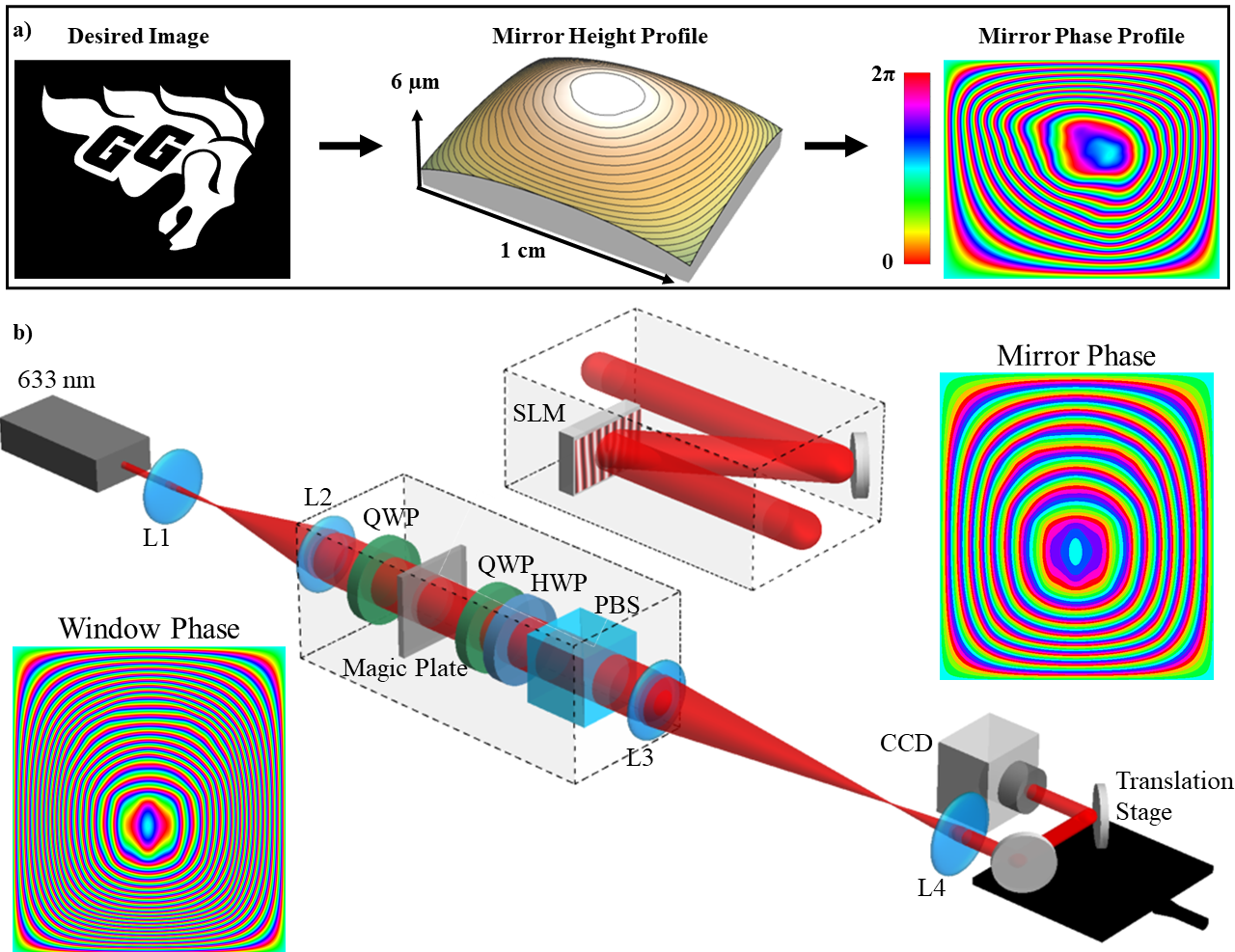
The goal of the experiment is to show a magic mirror and magic plate using liquid crystal technology in an SLM and PBOE, respectively. To achieve this, we must generate the phase pattern corresponding to the chosen intensity image. The image patterns that we use are converted to a bitmap form such that the pixels contain only a 1 or 0 for the intensity, see Fig. 1-a. Based on Eq. (1) the discretized intensity function is then used to find the height of the surface relief , where at the image plane. The inverse of the Laplacian is solved numerically with Dirichlet boundary conditions using the 2-dimensional discrete sine transform. In the case of flat optics, we are not varying the height of the window, but rather the index of refraction . Thus, Eq. (1) becomes , where is the transverse spatially dependent index of refraction of the plate. The resulting window phase pattern, as shown in Fig. 1-a, is plotted in radians.
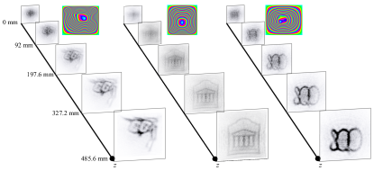
The magic mirror is realized using a Hamamatsu SLM with a screen resolution of 800 by 600 pixels. Figure 1-b shows the detail of the experimental setup for both magic mirror and magic plate. Given the desired image, the required phase pattern for the mirror is computed. There is a freedom to increase the steepness of the pattern, i.e., increasing the number of times the phase pattern goes from 0 to . This can be seen as altering the concavity of the mirror which results in changing how quickly the image is formed. In practical settings, care must be taken in choosing the window size and phase steepness. Due to beam divergence, an image which forms too slowly will lose its sharpness. At the same time, the pattern must be smooth enough such that caustics are not formed before the image plane berry2017laplacian . The phase pattern was uploaded to the SLM with the addition of a vertical grating. The first order of diffraction is selected, filtering out the rest using an iris in the center of a 4-f lens system, to remove unconverted light resulting from inefficiencies in the SLM. In addition to selecting the first order of diffraction, the 4-f lens system is also used to image the SLM plane and probe the intensity at different propagation distances. The evolution of the intensity distribution is recorded on a CMOS camera from the plane of the SLM down to the image formation planes. Additional planes were also imaged beyond the latter to capture the formation of caustics. The implementation of three SLM magic mirrors is shown in Fig. 2, where the intensity distribution smoothly evolves from the input beam profile to the desired image pattern.
As the next step, we bring together the concepts of magic window imaging and photonic spin-orbit coupling. Such a device, which we call the spin-orbit magic plate, is based on PBOEs, i.e., slabs of uniaxial anisotropic materials (liquid crystals, in our case) with an extraordinary axis orientation that is spatially varying in the plate’s plane. The action of a PBOE element with extraordinary axis orientation and (spatially uniform) retardation is given by
| (2) |
where and stand for the left and right circular polarization unit vectors, respectively. The sample optical retardation, , can be tuned by applying an AC voltage to the plate. Here, we can see that a perfectly tuned PBOE with results into the complete conversion of the input circular polarization to the opposite handedness with the addition of the desired phase , where is the inverse Laplacian of the image. Therefore, by flipping the incident polarization state from left to right handed, one can gain a and phase at the output, respectively.
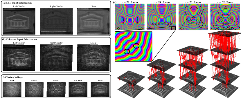
The University of Ottawa logo was chosen to be used for the spin-orbit magic plate. The plate is fabricated in our own liquid crystal facility larocque2016 . A pair of ITO glass plates are spin-coated with a polyamide. The ITO plates then are kept at 4 m-distance using spacers, and glued to each other with epoxy glue. The chosen polyamide can be photoaligned through illumination from linearly polarized UV light. We are able to control the orientation of the polyamide by changing the polarization of an incident UV-beam on a pixel by pixel basis by using a digital micromirror device (DMD). The pattern written on the polyamide dictates the orientation of the liquid crystal molecules, which are added between the plates in the successive stage. The pattern was written with 32 phase steps, thus 32 polarization settings illuminating different parts of the plate. We characterized the action of the fabricated plate illuminating it with both incoherent and coherent light. The magic plate optical retardation was set to by applying an AC voltage. An incoherent source, emitted light from an LED followed by a polarizing beam splitter, was used to illuminate the magic plate. The light was filtered with a bandpass filter centered at 633 nm. We choose the input polarization to be either linear or right/left circular by using a quarter-wave plate before illuminating the magic plate. The transmitted intensity was recorded on the CMOS camera. With the linear polarized input, we observe the simultaneous formation of the University of Ottawa logo and its negative image (with an imperfect overlap due to polarization dependent lensing), as shown in Fig. 3-a. The appearance of the negative image is due to the input right circular polarization component, which gains the phase (this has the effect of flipping the relative sign in Eq. (1)). It is possible to isolate the image or its negative by choosing input left or right circular polarization, respectively (Fig. 3-a). Similar effects are observed in the case of illumination with a coherent laser beam. We used a He-Ne laser ( nm) prepared with left/right circular or linear polarization. The resulting intensity in the case of input left circular polarization corresponds to the desired pattern (Fig. 3-b). We also observe fringes due to the transverse coherence of the source. As in the incoherent illumination case, an input right circular polarization gives rise, within the magic window theory approximations, to the negative of the desired image. When a beam with linear polarization is sent onto the magic plate, as opposed to one of the circular polarizations, the resultant image is a coherent linear combination of the images one would achieve from a left and right circular input. Moreover, the magic plate optical retardation can be altered to not be , but any other values. In Fig. 3-c, we show how, by tuning the optical retardation , we can switch, at a given plane, between the input beam intensity distribution and the image encoded in the plate. The interplay between source coherence and polarization conditioned action of the device leads to the formation of polarization singularities during the beam propagation. The polarization of an optical field can generally be described by the ellipse traced out by the electric field vector upon propagation. The polarization ellipse can then be defined by how close the ellipse is to a circle, its ellipticity, and the orientation of the ellipses major axis, called the azimuth. The polarization azimuth is defined as the phase of , where is the angle of the polarization ellipse, and and are the Stokes parameters defined in terms of the measured intensity patterns of the horizontal (), vertical (), diagonal (), and antidiagonal () polarizations, respectively dennis2009singular . When an electric field has a non-uniform polarization pattern, an interesting phenomenon can arise whereby the polarization azimuth is undefined. These singularities of the complex scalar field are called C-points. C-points are loci of exactly circular polarization, thus the orientation of the major axis of the polarization ellipse cannot be defined. When the magic plate is illuminated by linearly polarized light, the outgoing beam has both the right and left circular component, whose propagation is dictated by, respectively, the plate phase and the negative of the plate phase. The interaction of these two co-propagating beams gives rise to C-points with different topological charges. In the plane of the liquid crystal magic plate, the polarization remains uniformly linear, since we still have a uniform intensity distribution, albeit with a different phase for the left and right components, i.e., . It is not until propagation to the image plane where differences in the intensity pattern of the right and left components result in the appearance of the polarization C-points. Due to conservation of total topological charge, C-points appear at given planes in pairs with opposite topological charges. The free-space dynamics of the C-points generated here is rich and requires to be investigated individually.
In summary, we have realized a liquid crystal-based magic plate exploiting the principle of light manipulation with flat optics, where the impinging light wavefront is modulated by an inhomogeneous refractive index distribution. By exploiting the physics of patterned anisotropic media, we fabricated a flat spin-orbit magic plate. This device, depending on whether the input polarization is circularly left- or right-handed, creates a desired pattern or its negative, respectively. The flat magic plate can be tuned for operation at different wavelengths since its optical retardation can be adjusted by applying an external electric field to the plate. The working principle was demonstrated for both incoherent and coherent sources. In the latter case, interference effects lead to the formation of polarization singularities (C-points) whose trajectories were experimentally reconstructed.
E.K. acknowledges the fruitful conversation with Sir Michael Berry. This work was supported by Canada Research Chairs; Ontario Early Research Award (ERA); Canada First Research Excellence Fund (CFREF) and Natural Sciences and Engineering Research Council of Canada (NSERC).
References
- (1) Berry, M. V. Oriental magic mirrors and the laplacian image. European journal of physics 27, 109 (2005).
- (2) Ayrton, W. E. & Perry, J. Ii. the magic mirror of japan. part i. Proceedings of the Royal Society of London 28, 127–148 (1879).
- (3) Kugimiya, K. Characterization of polished surfaces by “makyoh”. Journal of crystal growth 103, 461–468 (1990).
- (4) Laczik, Z. J. Quantitative makyoh topography. Optical Engineering 39, 2562–2567 (2000).
- (5) Kugimiya, K. Characterization of polished mirror surfaces by the “makyoh” principle. Materials Letters 7, 229–233 (1988).
- (6) Berry, M. V. Laplacian magic windows. Journal of Optics 19, 06LT01 (2017).
- (7) Brand, M. & Birch, D. A. Freeform irradiance tailoring for light fields. Optics express 27, A611–A619 (2019).
- (8) Larocque, H. et al. Arbitrary optical wavefront shaping via spin-to-orbit coupling. Journal of Optics 18, 124002 (2016).
- (9) Cohen, E. et al. Geometric phase from aharonov–bohm to pancharatnam–berry and beyond. Nature Reviews Physics 1, 437–449 (2019).
- (10) Flossmann, F., Kevin, O., Dennis, M. R. & Padgett, M. J. Polarization singularities in 2d and 3d speckle fields. Physical review letters 100, 203902 (2008).
- (11) Larocque, H. et al. Reconstructing the topology of optical polarization knots. Nature Physics 14, 1079–1082 (2018).
- (12) Dennis, M. Polarization singularities in paraxial vector fields: morphology and statistics. Optics Communications 213, 201–221 (2002).
- (13) Cardano, F., Karimi, E., Marrucci, L., de Lisio, C. & Santamato, E. Generation and dynamics of optical beams with polarization singularities. Optics express 21, 8815–8820 (2013).
- (14) Dennis, M. R., O’Holleran, K. & Padgett, M. J. Singular optics: optical vortices and polarization singularities. Progress in optics 53, 293–363 (2009).