Max-Min Energy-Efficiency Fair Optimization in STAR-RIS Assisted System
Abstract
In this paper, we investigate simultaneously transmitting and reflecting reconfigurable intelligent surfaces (STAR-RIS), which enables to communicate with users both sides by transmitting signals to users forward and reflecting signals to users backward simultaneously. We consider a communication system with a STAR-RIS, a base station (BS) and many users to maximize the minimum user energy efficiency (EE) by jointly optimizing the active beamforming, transmission and reflection coefficients with BS power consumption limited. To solve this optimization problem efficiently, we divide it into two subproblems to optimize the transmitting beamforming matrix and phase shifts of STAR-RIS seperately. With the two subproblems fixed, an Alternating Optimization (AO) method is proposed to solve the maximize minmum user EE fair optimization problem. Numerical results can demonstrate that STAR-RIS behaves better than traditional reflecting-only RIS, and the algorithm we desigend can maximize the minum EE problem efficienty to ensure user fairness.
Index Terms:
STAR-RIS, MIMO, energy efficiency, phase shift, non-convex optimization, alternating maximization.I Introduction
The upcoming 6G wireless network demands high spectral efficiency (SE) and massive connectivity. Since high channel capacity has been considered widely, energy efficiency (EE), defined as the ratio of SE over power consumption, becomes the focus of our research. Traditional relay in wireless communication network inevitably brings a lot of hardware loss, thus reconfigurable intelligent surface (RIS) is considered a promising new technology for reconfiguring the wireless propagation environment through software controlled reflection.
Reflecting-only RISs have been fully investigated in wireless communication systems to enhance transmission quality [1] and maximize RIS-assited system EE[2, 3]. However, RISs who can only reflect incident signals face significant spatial limitations that all the users have to be the same side of RIS. In order to overcome this absolute space limitation and to meet the needs of our 360-degree users, we propose the concept of simultaneous transmitting and reflecting RIS (STAR-RIS) in this letter. While retaining the reflected signal characteristics of RIS, STAR-RIS can also transmit incident signals to users behind itself at the same time. Based on its own electromagnetic physical characteristics, both the reflected and transmitted signals can be adjusted and reconstructed by reflection and transmission coefficients of STAR-RIS. The users in front of STAR-RIS receive reflected signals, while users behind it receiving transmitted signals, thus enabling 360-degree communication.
As an arising technology, there are plenty of papers introducting STAR-RIS assisted communication systems. A general hardware model for STAR-RISs is presented in [4]. Channel models are proposed for the near-field and the far-field scenarios, base on which the diversity gain of the STAR-RIS is analyzed and compared with that of the conventional reflecting-only RIS. Numerical simulations can verify analytical results and to demonstrate that full diversity order can be achieved on both sides of the STAR-RIS. Based on its unique simultaneous transmission reflection mechanism, three practical transmission protocols are shown in [5], namely energy splitting (ES), mode switching (MS), and time switching (TS). Literature [5] desicribe a STAR-RIS aided downlink communication system considered for both unicast and multicast transmission, where a multi-antenna base station (BS) sends information to two users on each side of the STAR-RIS. A power consumption minimization problem for the joint optimization of the active beamforming at BS and the passive transmission and reflection beamforming at the STAR-RIS is formulated for each of the proposed operating protocols, subject to communication rate constraints of the users. Numerical results reveal that the required power consumption for both scenarios is significantly reduced by employing the proposed STAR-RIS instead of conventional reflecting/transmiting-only RIS. Paper [6] aims to characterize the fundamental coverage range of STAR-RIS aided communication networks. An AP communicates with one transmitted user and one reflected user employing both non-orthogonal multiple access (NOMA) and orthogonal multiple access (OMA) with the aid of an STAR-RIS [6]. A sum coverage range maximization problem is formulated for each multiple access scheme.
In this paper, we propose a maximize minmum user EE optimization to ensure communication fair among transmitting and reflecting users [7]. According to user’s relative location, they are divided to reflecting users and transmitting users depending on whether it’s in front or behind STAR-RIS. Given BS limited power consumption, we jointly optimize the power allocating matrix, transmitting and reflecting coeffients matrixs of STAR-RIS to maximize the minal EE problem. By decomposing it into two subproblems, the semi-definite relaxation (SDR) approach [8, 9]and successive convex approximation (SCA) [10] is applied to optimize the beamforming vectors at the BS and the phase shifts of STAR-RIS. Finally, AO algorithm is utilized to solve the original max-min EE optimization problem.
The layout of this work is organized as follows: STAR-RIS and relative works are introduced in Section I. Section II investigates the signal model and power consumption model of STAR-RIS aissited communication system. An efficient optimization algorithm is proposed for the energy splitting (ES) scheme in Section III to solve the max-min EE optimization problem. Section IV shows the numerical results.
Notation: is a scalar, is a vector, and is a matrix. , , , and denote transpose, Hermitian (conjugate transpose), inverse, and Frobenius norm of , respectively. , , and denote the real part, modulus, conjugate and the angle of a complex number, respectively. denotes the trace of a matrix and (with ) is the identity matrix. is a diagonal matrix with the entries of on its main diagonal. means that is positive semidefinite. is the imaginary unit.
II System Model
II-A System Model
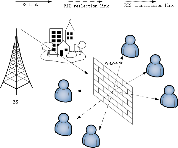
Consider a downlink communication system consisting of one BS equipped with M antenna element and K single-antenna mobile users. In the STAR-RIS aided system, the BS broadcasts independent superposed data streams to the users with beamforming vectors {, ,…, }, where is the active beamforming vector for user . We assume that this communication takes place via RIS with N reflecting elements simultaneously transmitting and reflecting signals emmitted from BS to users on both sides, as illustrated in Fig. 1. The direct signal path between BS and mobile users is intercepted due to the buildings between them.
The received signal at the -th user is given by
| (1) |
where suggests the receiving matrix between RIS and -th user, represents the transmission characteristics from the BS to the RIS. represent the transmit beamforming vector from BS to user, is the RIS coefficient diagonal matrix which is defined as
Spectrum efficiency
| (2) |
For convenience, let us define the equivalent channel spanning from the BS to the -th user .
II-B User Power Consumption Model
Composed of the BS transmit power, the hardware static power consumed in the BS, mobile user terminals and RIS, -th user will consume the power to connect with BS, which can be expressed as
| (3) |
where , is the efficiency of the transmit power amplifier, represents the transmit power, denotes the hardware static power of -th UE, and denote the total hardware static power consumption by BS and RIS, respectively. Furthermore, the total power consumption of each user can be expressed as
| (4) |
where is devided into transmitting energy consumption and static circuit power consumption for reciever . Define the EE for each user as the data rate for user k per total dissipation power which is given by
| (5) |
II-C Design Problem Formulation
We are interested in maximizing the minimum EE of users to guarantee fairness among them by jointly optimizing the transmit beamforming vectors at the BS, and the transmitting and reflectionphase shifts at the RIS, appearing in the diagonal of . The BS release constant transmit power continuously.
The considered maximize power problem is expressed as follows:
| (6a) | ||||
| s.t. | (6b) | |||
| (6c) | ||||
| (6d) | ||||
where denotes the individual QoS constraint of the user, represents the total static power in the system. Constraint(6b) nsures that the sum of the powers to reach the RIS is equal to a fixed value. Constraint(6c) promises each user can get qualified signal whose SNR reached . Constraint(6d) explains physical constraints to the transmission and reflection coefficients of every STAR-RIS elements.
III Optimization Formulation And Analysis
In this section, we investigate Alternating Optimization(AO) approach to handle problem efficiently by dividing it into two subproblems.
III-A Transmit Beamforming Matrix Optimization with Fixed Phase Shift Matrix
First, we apply non-liner (NL) fractional programming theory [11] to solve the fractional problem. Hence, can be formulated as:
| (7a) | ||||
| s.t. | (7b) | |||
| (7c) | ||||
| (7d) | ||||
According to Dinkelbach algorithm [12], the fractional problem has the following form:
| (8) |
Theorem 1: The optimal solution to the problem in (7) is achieved if and only if:
| (9) |
It is not hard to find that equivalent problem (III-A) is strictly decreasing in . To facilitate the solution design and to smooth the objective function, an auxiliary variable is introduced so that the equivalent form (6a) can be expressed as:
| (10a) | ||||
| s.t. | (10b) | |||
| (10c) | ||||
| (10d) | ||||
| (10e) | ||||
Up to now we have finished the hard fractional objective function. By applying the AO algorithm with fixed phase shifts, problem () can be reformulated as the following equivalent problem:
| (11a) | ||||
| s.t. | (11b) | |||
| (11c) | ||||
| (11d) | ||||
To optimize this sub-problem, the semi-definite relaxation (SDR) approach is applied to optimize the beamforming vectors at the BS. Given the reflection and transmitting matrix of RIS , is certain therefore. Define , where matrix is semi-definite and satisfies rank() 1. By applying SDR technique [8], we have:
| (12) |
| (13) |
Thus, the subproblem can be restated as:
| (14a) | ||||
| s.t. | ||||
| (14b) | ||||
| (14c) | ||||
| (14d) | ||||
The proposed algorithm for solving (P3) is given in Algorithm 1, to settle this sub-problem.
With solved, we notice that the relaxed is a standard semi-definite programming (SDP) [13] which can be solved by using CVX [14]. Hence, a tractable form of (P2) is obtained where we handle (P3) instead of (P2).
Up to now, we have figured out the beamforming vectors at the BS. Next, we attempt to optimize the reflection and transmitting matrix at the STAR-RIS by utilizing the AO algorithm [7].
III-B Transmitting and Reflection Phase Shifts Matrix Optimization with Fixed Transmit Beamforming
Given the transmitting beamforming vetor , we go back to our original problem model (6). Denote and . where , rank() =1 and []n,n = , c . All STAR-RIS elements simultaneously operate in transmitting and reflecting modes under the energy splitting (ES) protocol. Hence, we have
| (15) |
where = and the matrix is defined as:
Thus, the transmission and reflection phase shifts optimization problem in (6) with fixed active beamforming vectors can be formulated as:
| (16a) | ||||
| s.t. | ||||
| (16b) | ||||
| (16c) | ||||
| (16d) | ||||
| (16e) | ||||
where c . It can be concluded that (16e) makes non-convex. According to [15, 16], the non-convex rank-one constraint (16e) can be replaced by the following relaxed convex constraint:
where denotes the maximum eigenvalue of matrix , is a relaxation parameter in the -th iteration, which controls to trace ratio of . Specifically, = 0 indicates that the rank-one constraint is dropped; = 1 is equivalent to the rank-one constraint. Therefore, we can increase from 0 to 1 sequentially via iterations to gradually approach a rank-one solution. It is noted that is not differentiable, i.e., non-smooth. The following approximation expression can be used to approximate :
where is the eigenvector corresponding to the maximum eigenvalue of . Therefore, (16) is transformed to the following relaxed problem:
| (17a) | ||||
| s.t. | ||||
| (17b) | ||||
| (17c) | ||||
| (17d) | ||||
| (17e) | ||||
where . Problem (17) is a standard convex SDP, which can be solved efficiently by numerical solvers such as the SDP solver in CVX tool [14]. The parameter can be updated via [16]
| (18) |
where is the step size. Details of the proposed sequential constaint relaxation method is presented in Algorithm 2.
Based on the above discussions, we provide details of the proposed AO algorithm to solve the original max-min EE problem (6) in Algorithm 3.
IV Numerical Results
The environmental parameters are given as follows: the total number of users K = 6, BS antenna number M = 4, noise = -20dBm, SNR ratio threshold R = 6.6, RIS elements N = 30, system static power P = 5dBm and power emitted form BS Pmax = 50dBm. Having set the position parameters of the communication system, we verify the validity of our proposed approach through different user distributions. Via different reflected and transmitted users, we demonstrate that maximizing minimum user EE really works and ensure fariness between different type of users. Meanwhile, we also compare with traditional reflecting-only and transmitting-only RIS to see whether STAR-RIS has improved system performance indeed.
Firstly, we found that system EE grows with max energy power budget emitted by the BS in Fig 2, which means when Pmax is not big enough there’s plenty room in the system channel. Fig 3 indicates that average Spectral efficiency (SE) increases with Pmax almost synchronically. However when Pmax retains a growing tunrning point, EE comes to a slow growth phase gradually reaching the maximum limit of the system. We can conclude that different numbers of transmitting and reflection users don’t affect the EE optimization of the smallest user, and STAR-RIS performs better than reflecting-only and transmitting-only RIS.
Fig 4 shows that EE is improved due to the increase of RIS element numbers. In the given uniform other conditions, STAR-RIS always perform better than reflecting-only and transmitting-only RIS. The more number of RIS pieces, the larger RIS area will be. So it can reflect/transmit more transmitting signals and reduce leakage. Thus improve the minal user EE. The increasing curves grow fast or slow because area is to the second power not linear and signals radiated from BS is uneven.
In addition to the positive trend, performance of different situations in the face of increased system static power is also documented in Fig 5. Simply rising hardware power consumption will no doubtly decreases user EE. It is worth mentioning that STAR-RIS declines more moderately.
Fig 6 and 7 show the changes of EE and average SE when the system noise increases respectively. The increase of noise in communication system seriously affects the signal transmission quality, reduces the SNR ratio, and thus lower the user EE. It is not difficult to find that STAR-RIS assisted system performs better when facing larger noise power.
References
- [1] Q. Wu and R. Zhang, “Intelligent reflecting surface enhanced wireless network via joint active and passive beamforming,” IEEE, 2018.
- [2] Z. Yang, M. Chen, W. Saad, W. Xu, M. Shikh-Bahaei, H. V. Poor, and S. Cui, “Energy-efficient wireless communications with distributed reconfigurable intelligent surfaces,” 2020.
- [3] C. Huang, A. Zappone, G. C. Alexandropoulos, M. Debbah, and C. Yuen, “Reconfigurable intelligent surfaces for energy efficiency in wireless communication,” IEEE Transactions on Wireless Communications, vol. 18, no. 99, pp. 4157–4170, 2019.
- [4] J. Xu, Y. Liu, X. Mu, and O. A. Dobre, “Star-riss: Simultaneous transmitting and reflecting reconfigurable intelligent surfaces,” 2021.
- [5] X. Mu, Y. Liu, L. Guo, J. Lin, and R. Schober, “Simultaneously transmitting and reflecting (star) ris aided wireless communications,” 2021.
- [6] C. Wu, Y. Liu, X. Mu, X. Gu, and O. A. Dobre, “Coverage characterization of star-ris networks: Noma and oma,” IEEE Communications Letters, vol. PP, no. 99, pp. 1–1, 2021.
- [7] Li, Qiang, Hong, Mingyi, Wai, Hoi-To, Liu, and Ya-Feng, “Transmit solutions for mimo wiretap channels using alternating optimization,” IEEE Journal on Selected Areas in Communications, vol. 31, no. 9, pp. 1714–1727, 2013.
- [8] Z. Q. Luo, W. K. Ma, A.-C. So, Y. Ye, and S. Zhang, “Semidefinite relaxation of quadratic optimization problems,” IEEE Signal Processing Magazine, vol. 27, no. 3, pp. 20–34, 2010.
- [9] M. Fukushima, Z. Q. Luo, and P. Tseng, “Smoothing functions for second-order-cone complementarity problems,” Siam Journal on Optimization, vol. 12, no. 2, pp. 436–460, 2002.
- [10] M. Razaviyayn, M. Hong, Z. Q. Luo, and J. S. Pang, “Parallel successive convex approximation for nonsmooth nonconvex optimization,” advances in neural information processing systems, 2014.
- [11] H. Ishii, T. Ibaraki, and H. Mine, “Fractional knapsack problems,” Mathematical Programming, vol. 13, no. 1, pp. 255–271, 1977.
- [12] B. Kim, J. M. Kang, H. M. Kim, and J. Lee, “Max-min energy-efficiency optimization in wireless powered communication network with harvest-then-transmit protocol,” in 2016 6th International Conference on IT Convergence and Security (ICITCS), 2016.
- [13] A. Mobasher, M. Taherzadeh, R. Sotirov, and A. K. Khandani, “A near maximum likelihood decoding algorithm for mimo systems based on semi-definite programming,” IEEE Transactions on Information Theory, vol. 53, no. 11, pp. 3869–3886, 2007.
- [14] M. Grant, “Cvx: Matlab software for disciplined convex programming,” http://cvxr.com/cvx, 2008.
- [15] X. Mu, Y. Liu, L. Guo, J. Lin, and N. Al-Dhahir, “Exploiting intelligent reflecting surfaces in noma networks: Joint beamforming optimization,” IEEE Transactions on Wireless Communications, vol. PP, no. 99, pp. 1–1, 2020.
- [16] X. Mu, Y. Liu, L. Guo, J. Lin, and R. Schober, “Joint deployment and multiple access design for intelligent reflecting surface assisted networks,” 2020.