Also at ]Int. Centre for Theoretical Physics, Trieste, Italy
Also at ]National Institute of Chemical Physics & Biophysics, Tallinn, Estonia
Also at ]Dept. of Physics, Faculty of Science, Beni-Suef University, Egypt
Also at ]Department of Physics, School of Applied Mathematical and Physical Sciences, National Technical University of Athens, Athens, Greece
THE MoEDAL COLLABORATION
Search for Highly-Ionizing Particles in
Collisions at the LHC’s Run-1 Using the Prototype MoEDAL Detector
Abstract
A search for highly electrically charged objects (HECOs) and magnetic monopoles is presented using 2.2 fb-1 of collision data taken at a centre of mass energy (ECM) of 8 TeV by the MoEDAL detector during LHC’s Run-1. The data were collected using MoEDAL’s prototype Nuclear Track Detector array and the Trapping Detector array. The results are interpreted in terms of Drell-Yan pair production of stable HECO and monopole pairs with three spin hypotheses (0, 1/2 and 1). The search provides constraints on the direct production of magnetic monopoles carrying one to four Dirac magnetic charges (4) and with mass limits ranging from 590 GeV/c2 to 1 TeV/c2. Additionally, mass limits are placed on HECOs with charge in the range 10 to 180, where is the charge of an electron, for masses between 30 GeV/c2 and 1 TeV/c2.
pacs:
14.80.Hv, 13.85.Rm, 29.20.db, 29.40.CsThe quest for highly ionizing particle (HIP) avatars of physics beyond the Standard Model (SM) has been an active area of investigation at accelerator centres for several decades [1, 2, 3, 4, 5, 6, 7, 8, 9, 10, 11, 12, 13, 14, 15, 16, 17]. Searches have also been performed in cosmic rays and in matter [18, 19].
Most HIP searches can be divided into two categories: the quest for magnetic monopoles (MMs) and the hunt for highly electrically charged objects (HECOs). Also, according to the Bethe-Bloch formula [20], massive singly charged particles traversing matter can be highly ionizing at low velocity, (the particle velocity expressed as a fraction of the speed of light, ). The physics program of the MoEDAL experiment described [4] a number of such massive Singly Electrically Charged Object (SECO) HIP scenarios. Further studies have examined MoEDAL’s sensitivity to SUSY SECOs [21, 22] and doubly charged [22] SUSY particles.
In 1931 Dirac formulated a consistent description of a magnetic monopole [23] within the framework of quantum physics. This monopole is associated with a line of singularity called a Dirac string. Dirac derived his Quantization Condition (DQC) in order that this string has no physical effect:
| (1) |
where is the electric charge of the particle probe, is Planck’s constant divided by 2, is the magnetic charge, is the permeability of free space and is an integer.
The DQC indicates that if magnetic charge exists then the electric charge is quantized in units of . The value of is approximately 68.5. Dirac’s theory did not constrain the mass or the spin of the monopole. Further, the Dirac quantization condition indicates a coupling strength much bigger than one: 34. Thus, perturbation theory cannot be applied and cross-section calculations based on perturbation theory are not physically valid, although useful as a benchmark.
In 1974 ’t Hooft [24] and Polyakov [25] discovered monopole solutions of the non-Abelian Georgi-Glashow model [26]. This model has only one gauge symmetry, , with a three component Higgs field. The mass of the ’t Hooft-Polyakov MM was predicted to be around 100 GeV/c2. However, MMs with such a low mass were ruled out by experiment. Subsequently, Georgi and Glashow combined their electroweak theory with a theoretical description of strong nuclear forces to form a Grand Unified Theory (GUT) [27] using the single non-Abelian gauge symmetry, . In this GUT theory the MM would have a mass of 1015 GeV/c2 which is far too heavy to be directly produced at any foreseeable terrestrial collider.
The SM has an group structure that does not allow a finite-energy monopole. However, Cho and co-workers have modified its structure to admit the possibility of an “electroweak” monopole [28, 29] with a magnetic charge of 2. Based on this work, Cho, Kim and Yoon (CKY) [30] have more recently presented an adaptation of the SM –including a non-minimal coupling of its Higgs field to the square of its gauge coupling strength –that permits the possibility of a finite energy dyon [31].
In another extension of the SM there exists a topologically stable, finite energy magnetic monopole with a mass estimated to lie in range 900 GeV/c2 to 3 TeV/c2 [32, 33]. This extension retains the same gauge group as the SM but possesses an extended fermion and Higgs sector where right-handed neutrinos are non-sterile.
The question of whether it is possible to create generalizations of the CKY model that are consistent with the SM was considered by Ellis, Mavromatos and You (EMY) [38]. EMY concluded that there is a possibility that an “electroweak” monopole, consistent with the current constraints on the SM, may exist and be detectable at the LHC. The existence of a MM is such a theoretically well predicated and revolutionary possibility that the search for a MM has been carried out as each new energy frontier is broached.
We consider here only those models that admit a magnetic charge quantized in units of Dirac charge, , or a multiple of the Dirac charge. As = 68.5, a relativistic monopole with a single Dirac charge will ionize 4700 times more than a relativistic proton. It is thus a prime example of a HIP.
As mentioned above electrically charged HIPs, or HECOs, have also been hypothesized. Examples of HECOs, include: dyons [31], doubly charged massive particles [4]; scalars in neutrino-mass models [39]; aggregates of - [40] or -quark matter [41], -balls [42, 43] and the remnants of microscopic black-holes [44].
The first searches for MMs and/or HECOs at the LHC were performed by the ATLAS and MoEDAL Collaborations in 8 TeV collisions [5, 6, 9]. At this stage, the ATLAS monopole search was sensitive to singly magnetically charged (1) monopoles, whereas the MoEDAL search was sensitive to single and multiply charged monopoles. ATLAS and MoEDAL continued the quest for HIPs at Run-2.
In the case of MMs, the ATLAS and MoEDAL searches were complementary, in the sense that ATLAS utilized the MMs highly ionizing signature [8, 15] whereas, until now, the MoEDAL experiment only exploited the induction technique to directly detect the magnetic charge [10, 11, 12]. Extensive accelerator searches for HIPs at the LHC have also been undertaken [15, 8, 7, 5]. The latest result from the LHC is from an ATLAS experiment search for HECOs and monopoles using data taken during LHC’s Run-2 at a centre-of-mass energy of 13 TeV [16].
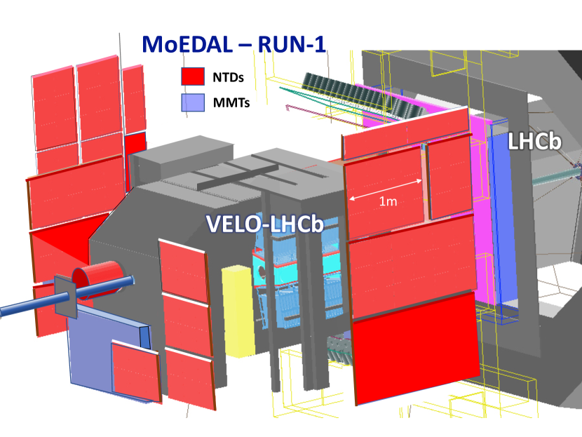
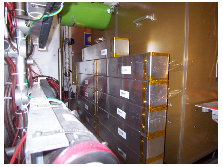
In this paper we report the first use of the prototype MoEDAL Nuclear Track Detector (NTD) System, which relies on an ionization signal to detect HIPs in conjunction with the prototype MoEDAL trapping detector system that utilizes a Superconducting Quantum Interference Device (SQUID) to detect the presence of trapped magnetic charge. The complete prototype detector is shown in Fig. 2. A total of 2.2 fb-1 of collision data was obtained during LHC’s Run-1 at intersection point IP8 on the LHC ring using this detector and analyzed for evidence of HECOs. The precision of the luminosity measurement at IP8 during Run-1 is estimated to be 1.16% [45].
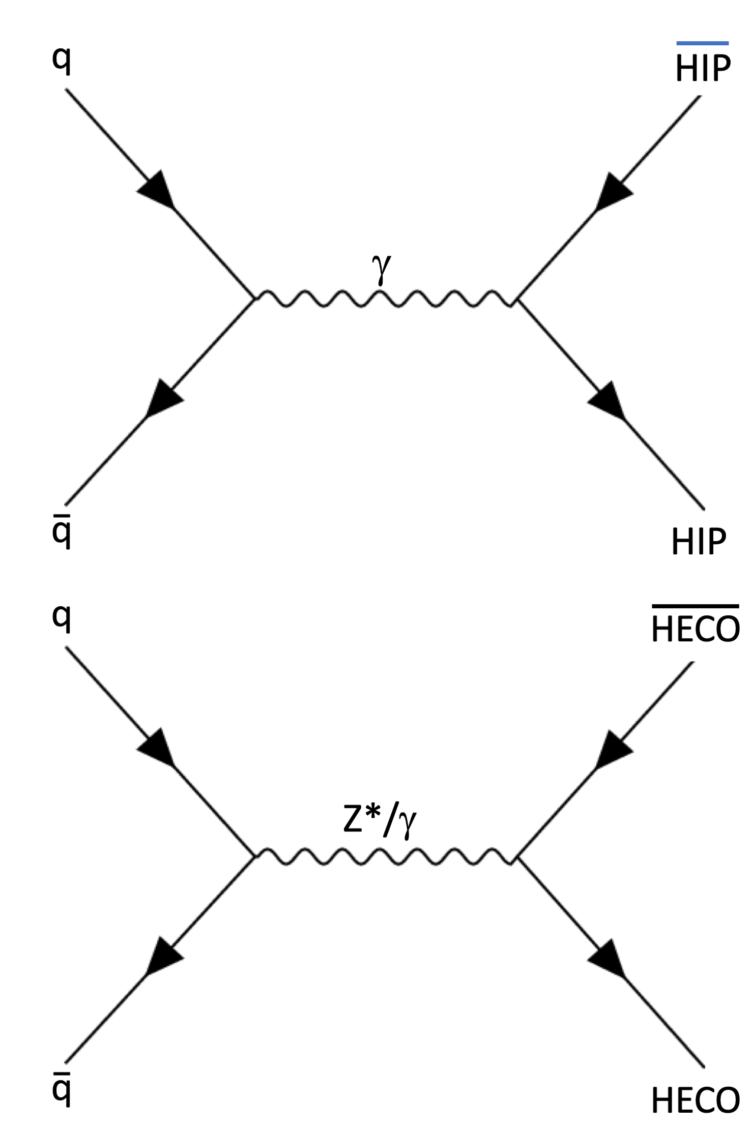
A DY mechanism provides a simple model for HIP pair production. Monopole pair production and spin-0 and spin-1 HECO pair production cross sections are computed using the Feynman-like diagram shown in Fig. 1(top). In the case of spin-1/2 HECOs DY production can take place via virtual photon or Z exchange [46], as depicted in Fig. 1(bottom). In the case of Drell-Yan processes of magnetic monopole production, the coupling of the magnetic charge to the Z boson is usually assumed to be absent. In specific models of such monopoles this is proven explicitly [32, 33], since any Z-flux that could exist in the monopole solution would be concentrated inside the monopole core. In the case of electrically charged dyons this issue is model dependent. The spin 1 magnetic monopole [34, 35] can have a non-zero magnetic moment, characterized by the parameter [36]. In this analysis the value =1 is used as it is the only one that respects unitarity [37].
It should be noted that the large monopole-photon coupling places such calculations in the non-perturbative regime. In the case of HECOs, which are characterized by large electrical charges, the Drell-Yan (DY) diagram shown in Fig. 1 should undergo appropriate resummation, to account for potential non perturbative quantum corrections, see e.g. [47], [48]. Such techniques are beyond the scope of this paper, and will be the topic of a future investigation.
I The MoEDAL Detector
MoEDAL’s detector technology is radically different from the general-purpose LHC experiments, ATLAS and CMS. The MoEDAL detector, deployed alongside LHCb’s VELO (VErtex LOcator) detector at IP8, employs two unconventional passive detection methodologies tuned to the discovery of HIPs. The first of these is a plastic NTD stack array to detect the ionization trail of HIPs. The second is a detector system comprised of aluminium absorber elements. This detector system is called the MMT (Magnetic Monopole Trapper) since it was used to trap HIPs with magnetic charge, that slow down and stop within its sensitive volume, for further laboratory analysis. Both of these detector systems are passive, requiring neither a trigger or readout electronics. The MoEDAL detector is described in more detail below.
The MoEDAL detector is exemplified by its ability to retain a permanent record, and even capture new particles for further study. The NTDs provide a tried-and-tested and cost effective method to accurately measure the track of a HIP and its effective charge. Importantly, the NTD response was directly calibrated using heavy-ion beams at the CERN SPS. The second detector system, the MMT, ensures that a small but significant fraction of the HIPs produced are slowed down, stopped and trapped for further study in the laboratory. There are no SM particles that can produce such distinct signatures. Thus, even the detection in MoEDAL of few HIP messengers of new physics would herald a discovery.
I.1 Energy Loss of HIPs in MoEDAL
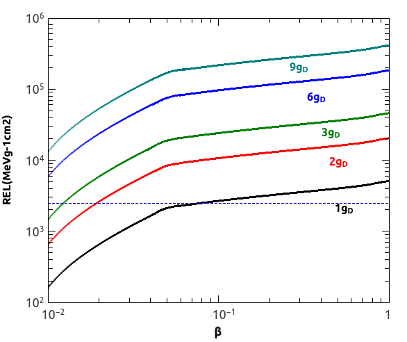
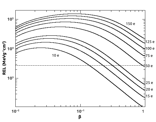
In the MoEDAL detector HIPs lose energy by ionization. The energy loss by ionization in the MMT detector is computed using Bethe-Bloch formula. For NTDs, the relevant quantity is the Restricted Energy Loss (REL) [49]. For 10-2, the REL is equal to the particle’s total energy loss in the medium. At larger velocities, REL is the fraction of the electronic energy loss leading to the formation of -rays with energies lower than a cut-off energy Tcut. The REL can be computed from the Bethe-Bloch formula restricted to energy transfers TTcut with Tcut a constant characteristic of the medium. For Makfrofol, which is the MoEDAL NTD used for the analysis reported in this paper, T 350 eV. The RELs for MMs and for HECOs in Makrofol are shown in Fig. 3 and Fig. 4, respectively.
I.2 The MMT Detector
The prototype MMT detector deployed for LHC’s Run-1 consisted of 198 aluminium rods weighing a total of 163 kg. These rods were housed in an enclosure placed just underneath the beampipe at the upstream end of LHCb’s VELO detector as shown in Fig. 5. After exposure the MMT’s aluminium volumes are sent to the ETH Zurich Laboratory for Natural Magnetism where they are passed through a SQUID magnetometer to scan for the presence of trapped magnetic charge. A monopole will stop in the MMT detector when its speed falls below 10-3. It then binds due to the interaction between the monopole and the nuclear magnetic moment[50, 51, 52, 53] of an aluminium nucleus comprising a MMT trapping volume.
The anomalously large magnetic moment of an aluminium nucleus gives rise to a monopole-nucleus binding energy of 0.5 - 2.5 MeV [50], comparable to the shell model splittings. In any case, it is reasonable to assume that the very strong magnetic field of the monopole will rearrange the nucleus, permitting it to bind strongly to the nucleus. As reported in Ref. [50] monopoles bound in such a way would be trapped indefinitely. It would require fields well in excess of several Tesla for the lifetime of the trapped monopole state to compromise its detection by the MoEDAL trapping detector. We note that the MoEDAL detector is only subject to fields lower than 10 mT.
I.2.1 Calibration of the MMT Detector
A magnetic monopole captured in an MMT volume is tagged and measured as a persistent current in the SQUID coil encircling the samples’ transport axis that passes through the SQUID magnetometer. The calibration of the magnetometer response is achieved using two independent techniques. In brief, the magnetometer calibration was obtained using a convolution method applied to a dipole sample, and validated using long thin solenoids that simulate a monopole of well-known magnetic charge. For more details see Ref. [54]. These calibration methods agree to within 10%, which is taken as the pole strength calibration uncertainty. The magnetometer response has been determined by measurement to be charge-symmetric and linear in a range of magnetic charge 0.3 - 300 .
I.3 The Nuclear Track Detector System
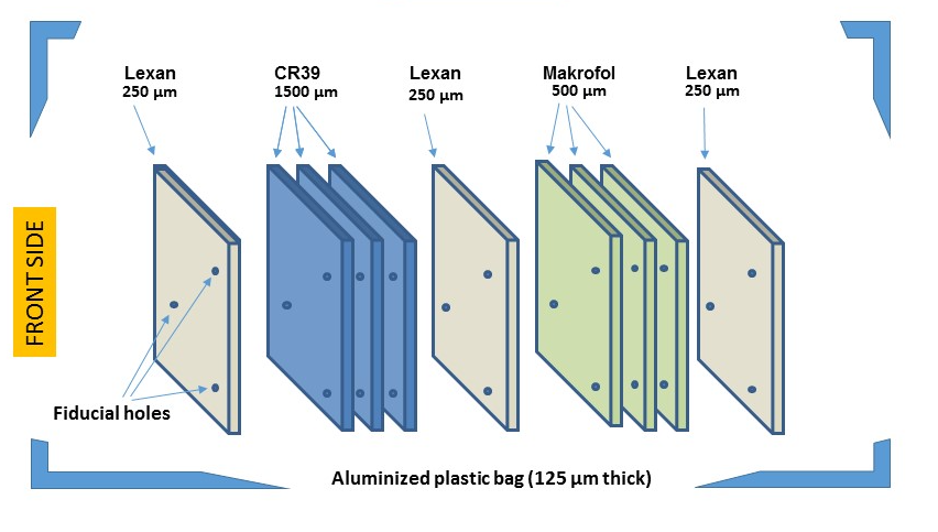
The MoEDAL NTD is arranged in modules deployed around IP8 in the VELO cavern. A prototype NTD array of 125 25 cm 25 cm stacks was installed for Run-1 as shown in Fig. 2. Each module comprises three layers of 1.5 mm thick CR39® polymer, three layers of Makrofol DE® and three layers of Lexan® 0.5 and 0.25 mm thick, respectively, inside Aluminium bags (Fig. 6). Currently the Lexan® foils serve as protective layers and are not analyzed.
In this analysis only the Makrofol NTDs are utilized. This is due to roughly a factor ten higher detection threshold in Makrofol than CR39 which results in substantially less “visual noise” in the etched plastic large due to spallation products arising from beam backgrounds. Beam background particles are generated by the interaction of the LHC beam with LHC machine elements and the machine environment. Thus, the analysis of the CR39 NTDs is considerably more time intensive. HIPs produced via the DY mechanism in LHC collisions during Run-1 are sufficiently highly ionizing that they can easily be detected with the Makrofol NTDs, obviating the need to scan the CR39 in the first pass. In the event of the observation of a candidate event in the Makrofol all 6 NTD sheets in the stack would have been analyzed.
I.3.1 The Etching Procedure
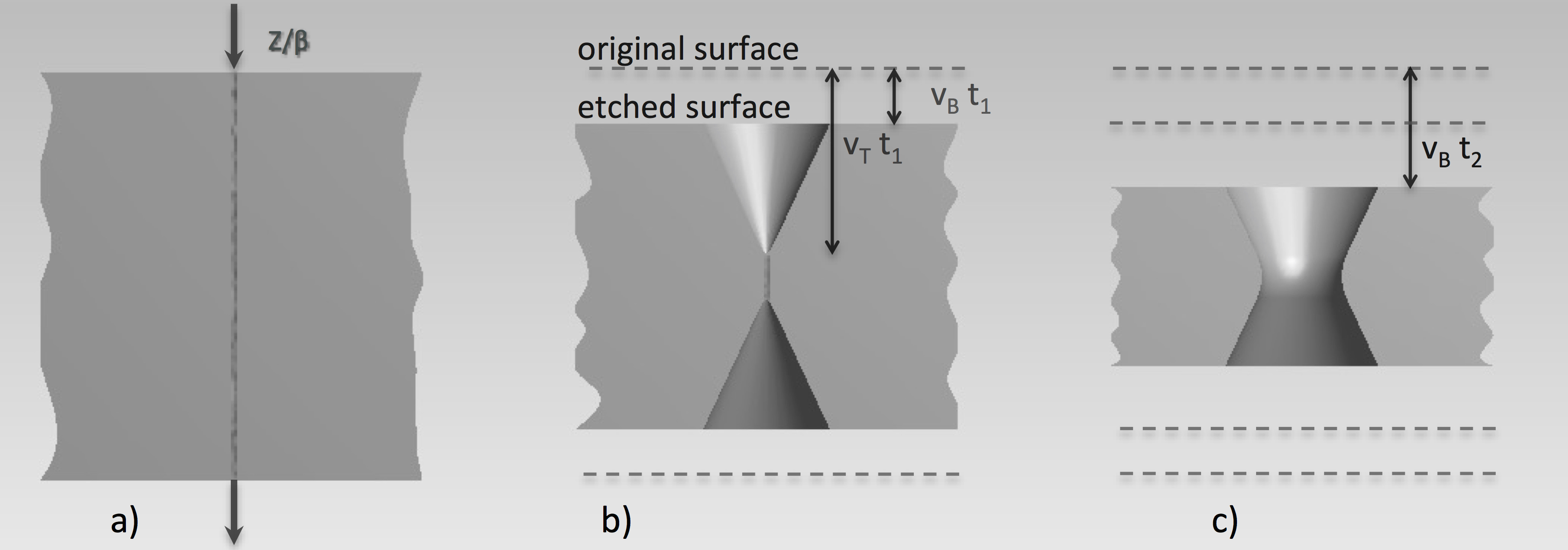
In plastic track-etch detectors, the passage of a heavily ionizing particle can produce a permanent damage of polymeric bonds in a cylindrical region (“latent track”) extending few tens of nanometers around the particle trajectory (Fig. 7). By subsequent chemical etching the latent track is “amplified” and can be made visible under an optical microscope. In the etching process, the bulk of the material is removed at a rate and at a higher rate along the latent track. The damage zone is revealed under an optical microscope as a pair of cone shaped etch-pits, one on each face of the NTD sheet. Etch-pits surface openings have a circular shape for normally incident particles, otherwise they are elliptical. A single well measured etch pit is called a “track” candidate. If another etch pit is measured on the NTD sheet that is consistent with being the twin then we have a confirmed track candidate.
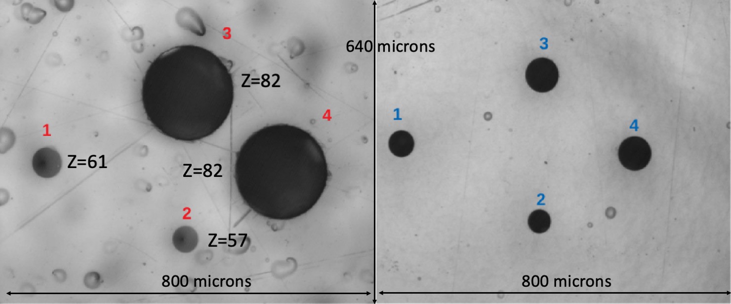
A sketch of an etch-pit at different etching times is shown in Fig. 7 for a normally incident particle crossing the detector with a constant energy loss. Two etching conditions were applied (Table 1). The first is the so-called “strong” etching condition, allowing faster etching and yielding larger etch-pits that were easier to detect under visual scanning. Strong etching was applied to the first, most upstream, Makrofol foil in each module. The second, “soft etching,” condition results in a slower etching process. This allows the etching process to proceed in several steps in order to follow the formation of etch-pits. Soft etching is applied to subsequent Makrofol foils in the stack, if a candidate track is found in the first layer. In Fig. 8 are shown microphotographs of relativistic Pb82+ tracks in Makrofol foils etched in (left) “strong conditions”; (right) “soft conditions.”
| Etching Conditions | ||
|---|---|---|
| Etching Mode | Etchant | vB(m/hour) |
| Strong | 6N KOH + 20% ethyl alcohol at 65∘C | 230.5 |
| Soft | 6N KOH + 20% ethyl alcohol at 50∘C | 3.40.05 |
I.3.2 Calibration of the NTD Detector
The response of the NTD is measured by the etching rate ratio, also called the reduced etch-rate, = vT/vB, as a function of the particle’s REL. Heavy ion beams are used to determine the detector response over a large range of energy losses, as discussed in ref. [55]. The Makrofol was calibrated with ion beams of 158 A GeV Pb82+ and 13 A GeV Xe54+ energy per nucleon, at CERN’s SPS. The calibration set-up included a stack of Makrofol foils placed upstream and downstream of an Aluminum target. Incoming ions undergo charge changing nuclear fragmentation interaction along their path through the detector foils and the target. After exposure the detectors were etched in 6N KOH+20 ethyl alcohol at 50 ∘C for 10 hours. The bulk etching velocity was vB = 3.4 m/h.
After etching, the size of the etch pits was measured with an automatic scanning system providing the cone base area, and the coordinates of the center of the etch pits. Etch pits diameters typically range from 10 m to 100 m, with a modal value in the range 30 m to 40 m. The base area distributions of incoming ions and of their fragments is shown in Fig. 9. The projectile fragments have the same velocity and approximately the same direction as the incident ions. From the base area spectrum, the charge corresponding to each nuclear fragment peak can be identified, and the corresponding REL determined. A detailed description of the calibration procedure can be found in [55].
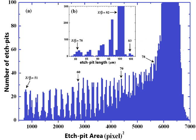
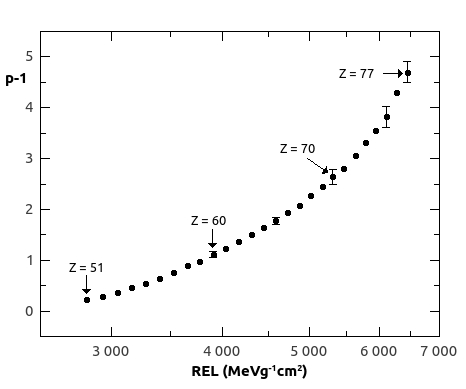
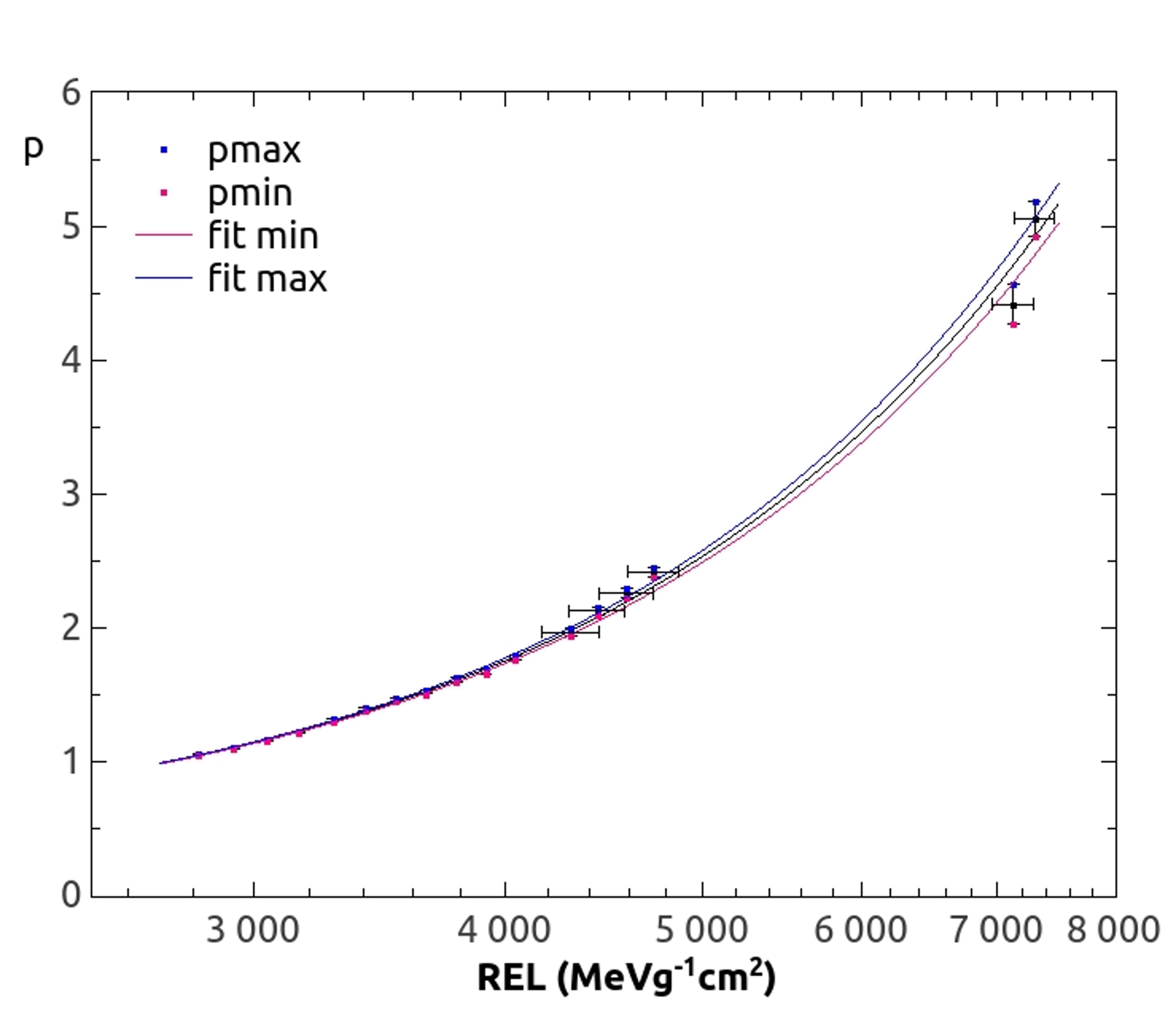
For each identified peak the reduced etch rate p, the Z/ and eventually the restricted energy loss are computed (Fig.9). Calibration data thus obtained are shown in Fig.10. For Makrofol, the mimimum detectable relativistic charge is Z/ 50, for both soft and strong etching. The REL corresponding to this detector threshold is 2700 MeV g-1cm2.
I.3.3 Etching and Scanning of MoEDAL NTD
After exposure in the LHC IP8 region, the MoEDAL NTD stacks were taken to the INFN etching and scanning laboratory in Bologna. A global module reference system is created by drilling three reference holes – 2 mm diameter – on each detector module. This coordinate system provides an accuracy of 100 m on the determination of the position of a particle track over the detector surface. The stacks are then unpacked, the detectors foils labelled and their thickness measured on a grid of points uniformly distributed over the foil surface.
For the search reported in this paper only Makrofol foils were analysed. In each exposed stack, the most upstream Makrofol layer was etched in 6 N KOH + 20% ethyl alcohol at 65∘C. After 6 hours etching, etch-pits as small as 10m would be detected under 20 magnification. An efficiency of 99% was estimated by scanning foils exposed to ions as described below.
Each Makrofol layer examined was manually scanned. Every detected surface structure was further observed under higher magnification and classified either as material defects or particle’s track. If a pair of etch-pits is detected on the front and back sides of the foil, it was observed at larger (100 - 500) magnification. From the etch-pit size on the “front” and “back” surfaces, and the bulk etching rate, the incidence angle on each surface is estimated. It takes around 2.5 hours to scan one side of a Makrofol layer when using the microscope at 32 total magnification.
A pair of collinear incident and exiting etch-pits, consistent with pointing to the IP, is defined as a potential candidate “track”. In particular, if a candidate is found in the first layer of a module the downstream Makrofol foils would be etched in 6 N KOH + 20% ethyl alcohol at 50∘C. The vast majority of spallation products arising from beam backgrounds have a very limited range in the NTD sheet, typically tens of microns, and only give rise to a single pit when the NTD sheet is etched.
An accurate scan of the downstream Makrofol sheets would then be performed using an optical microscope with high magnification (100 - 200 ) in a square region of about 1 cm2 around the candidate expected position. If collinear etch-pits are found in all three Makrofol sheets the CR39 would then be scanned for etch-pits collinear with those in the Makrofol layers. A HIP candidate track requires collinear etch-pits in all six NTD sheets in the stack that points to the IP. Additionally, the REL estimated from the etch-pits dimensions (surface area, etch-pit length) has to be consistent with the HIP hypothesis. However, no candidate “track” candidate was found.
I.3.4 The Detection Threshold for Makrofol
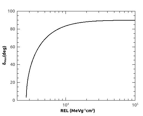
For the HIP to be detected its REL must be greater than the detection threshold of the Makrofol. The detection threshold will vary with the etching conditions. It will also vary with the angle of incidence () of the HIP on the NTD. The connection between the threshold and the maximum angle of incidence () to the normal to the NTD that the HIP can make and still be detected, is expressed by the relationship: , where is reduced etch-rate described above. The lowest threshold is obtained for a HIP impinging normally to the NTD. The curve obtained from a empirically based parameterization of the relation between and the REL is shown in Fig. 11. This parameterization is used in the determination of the acceptance for HIPs incident on the MoEDAL’s NTD stacks.
I.3.5 Efficiency and False Positives in the NTD Detectors
As described above the signal for the passage of a HIP messenger of new physics through a MoEDAL NTD stack would be a string of etch-pits in the stack, where an etch-pit pair is due to the ingress and egress of the HIP passing though an NTD sheet. No such signal has ever been seen in this search, or observed by any other HIP search employing NTDs [2]. Indeed, no candidates were seen in the 125 stacks examined (corresponding to 7.8 m2), where only the most upstream sheet of the NTD stacks were examined.
The absence of false positives using the NTD technique was also a feature of the astroparticle physics experiments MACRO [60] and SLIM [61] , which deployed a surface area of 1263 m2 and 427 m2, respectively. Neither experiment observed a single HIP candidate. It should be noted that the NTD technique employed by these experiments are essentially identical to those employed at colliders.
The lack of false positives in the NTD technique at colliders or in astroparticle physics experiment raises the question of the false negatives or detector efficiency, where a signal exists but is not seen. This can be evaluated using the heavy ion beams that are used to calibrate NTD detectors. In the absence of beam backgrounds, the detection, or scanning, efficiency for the etch-pits due to heavy-ion HIPs with ionizing power above the NTD threshold was measured to be in excess of 99% as described directly below.
In order to estimate the detection efficiency of NTDs for HIPs in the presence of beam backgrounds we utilized NTD calibration stacks exposed to a relativistic lead-ion beam as described above. The stacks were comprised of sheets of Makrofol NTDs exposed to the beam backgrounds (LHC-exposed sheets) in the VELO cavern at the LHC for a year of data taking, interleaved with Makrofol NTD sheets (LHC-unexposed sheets). Plastic from the same production batch was used in calibration and standard data taking.
The NTDs sheets comprising the calibration stacks were then etched in the same way as the standard NTD stacks deployed for data taking during Run-1. The individual sheets were scanned using the same manually controlled optical scanning microscope technology employed to examine all MoEDAL NTD stacks.
The relativistic lead-ion calibration beam particles penetrate the whole stack allowing the signal etch-pits seen in the LHC unexposed sheets - where the signal can clearly be observed with a 100% efficiency - to serve as a map. The identification of etch-pits in the LHC-unexposed sheets is measured to be 100% by making independent comparison scans of the other LHC-unexposed sheets in the stack which, of course, have the identical etch-pit number and pattern.
Using the LHC-unexposed sheets in the stack as a one-to-one same-scale map for the hits in the adjacent LHC-exposed sheets the scanning efficiency for LHC-exposed sheets can be measured. Such measurements indicate that the overall scanning efficiency for detection above threshold was in excess of 99%. This number was found by scanning the LHC-exposed sheets and then comparing the etch-pits found with the etch-pits identified in the adjacent LHC- unexposed stacks. Each sheet has exactly the same number and pattern of “ signal” etch-pits, resulting from the calibration beam - since the beam passes through the complete stack.
II Acceptance of the Run-1 MoEDAL Detector
The MoEDAL detector’s acceptance is defined to be the fraction of the number of events in which at least one HIP of the DY produced pair was detected in MoEDAL in either the NTD detector or the MMT detector. The acceptance for DY production of HECOs and magnetic monopoles is described by an interplay of the geometrical disposition of MoEDAL NTD modules and MMT detectors, energy loss in the detectors, mass of the particle and the spin-dependent kinematics of the interaction products. In the case of the HECOs, MoEDAL’s NTD system provides the only means of detection.
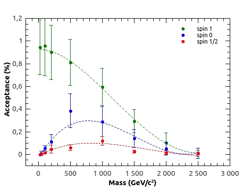
For a given HIP mass and charge, the pair-production model determines the kinematics and the overall trapping acceptance obtained. The uncertainty in the acceptance is dominated by uncertainties in the material description [9, 10, 11]. This contribution is estimated by performing simulations with hypothetical material conservatively added and removed from the nominal geometry model. An example, showing the MoEDAL NTD acceptance curves for spin-1/2, spin-0, spin-1 HECOs with charge 125 - produced by a DY process via virtual photon exchange - is shown in Fig. 12. Note that HECOs can only be detected by the NTDs since HECOs trapped in the MMT detector do not have a magnetic charge and hence cannot be detected in MoEDAL’s SQUID detector. These curves are determined by the kinematics of the produced particles convoluted with the VELO material immediately surrounding IP8 and the distribution of the MoEDAL NTD detectors. The prototype MoEDAL detector provides only a partial, non-uniform, coverage of the available solid angle.
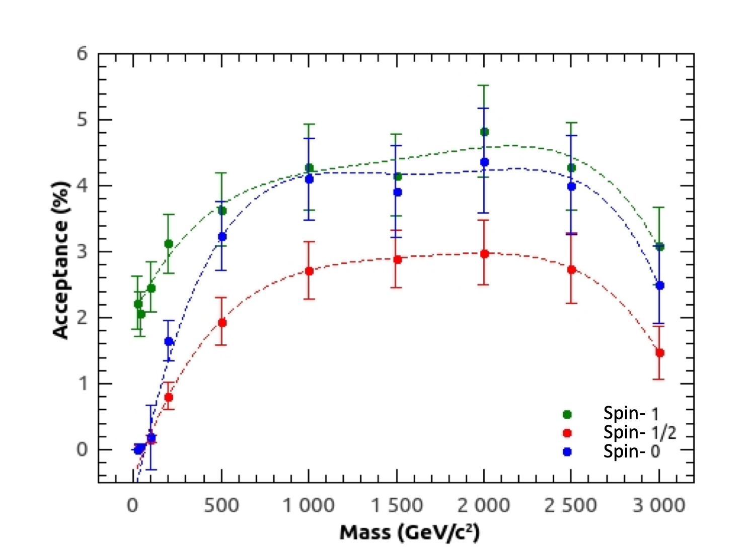
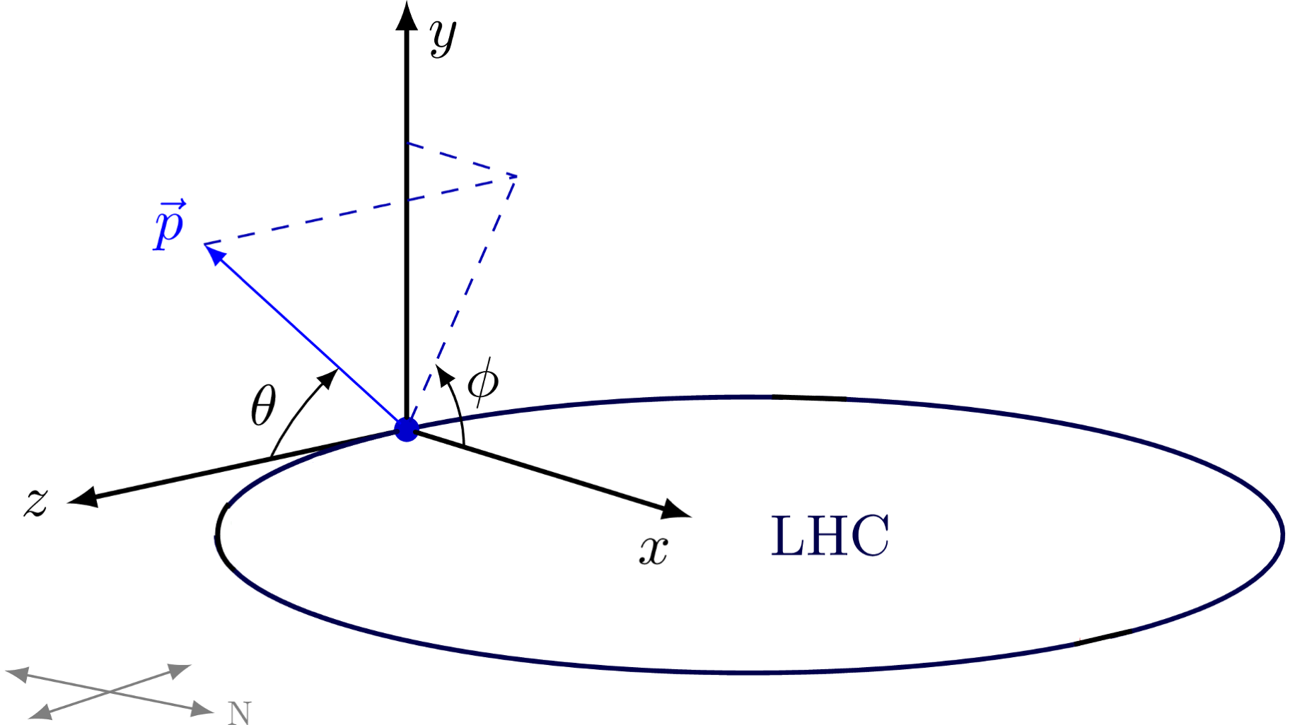
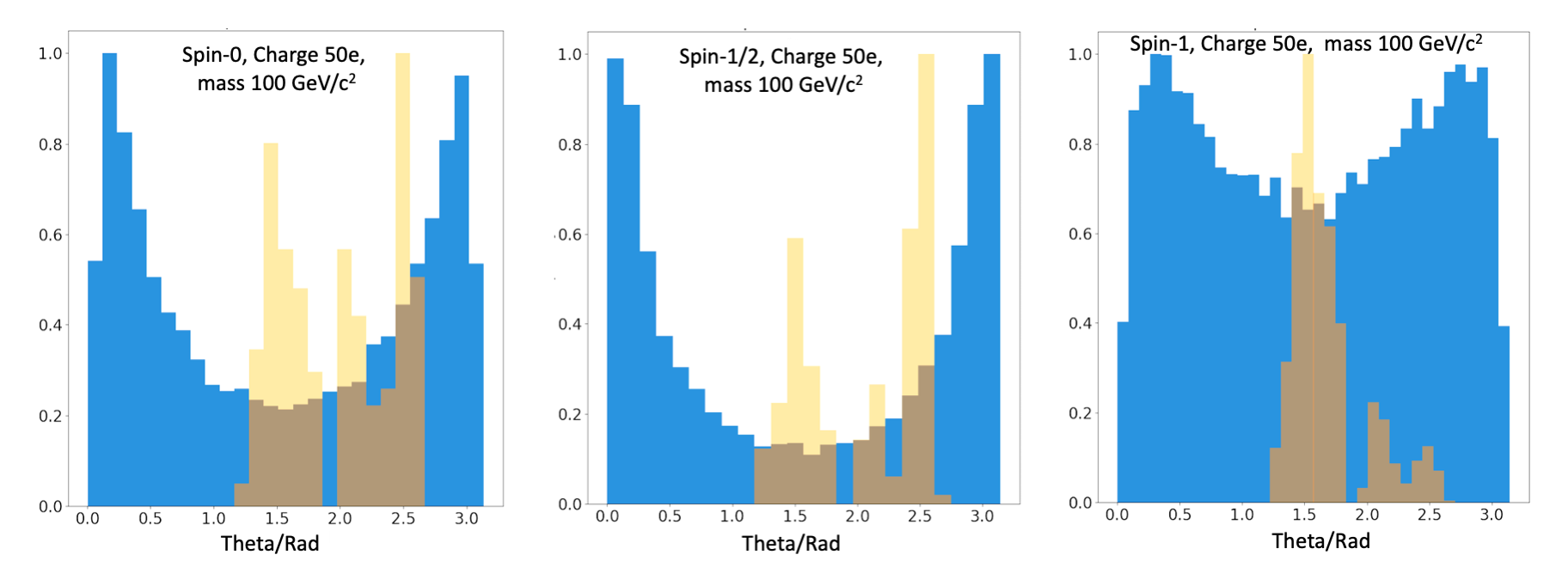
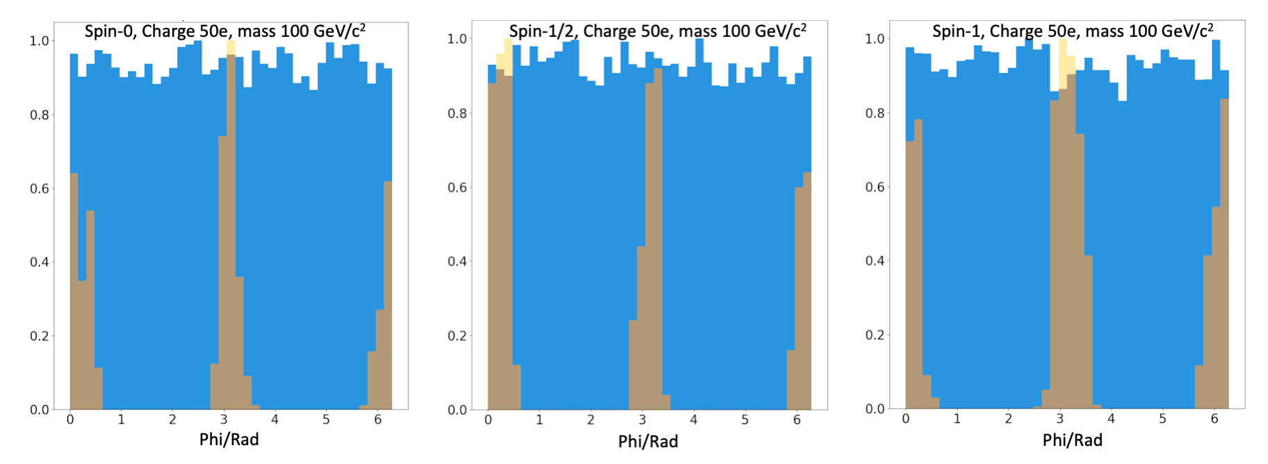
The acceptance curves for spin-0, spin-1/2 and spin-1 monopoles, found using the NTD and MMT detectors combined, are shown in Fig. 13. The acceptances shown in Fig. 12 and Fig. 13 refer to the prototype detector deployed for LHC’s Run-1. The acceptance for the Full Run-2 detector is somewhat larger. The difference between the acceptances for HECOs with spins with spin-1/2, spin-0 and spin-1, is mainly due to how well the disposition of the detector elements in theta () matches the corresponding theta distribution of the DY produced HECO’s. To illustrate this point we have compared the kinematic quantities (momentum (), theta () and phi () ) of the uncut signal to the corresponding distributions for the events that pass the selection criteria. The angles theta () and phi () are defined in Figure 14.
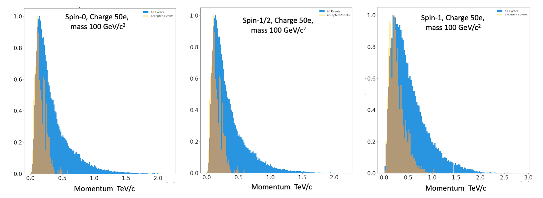
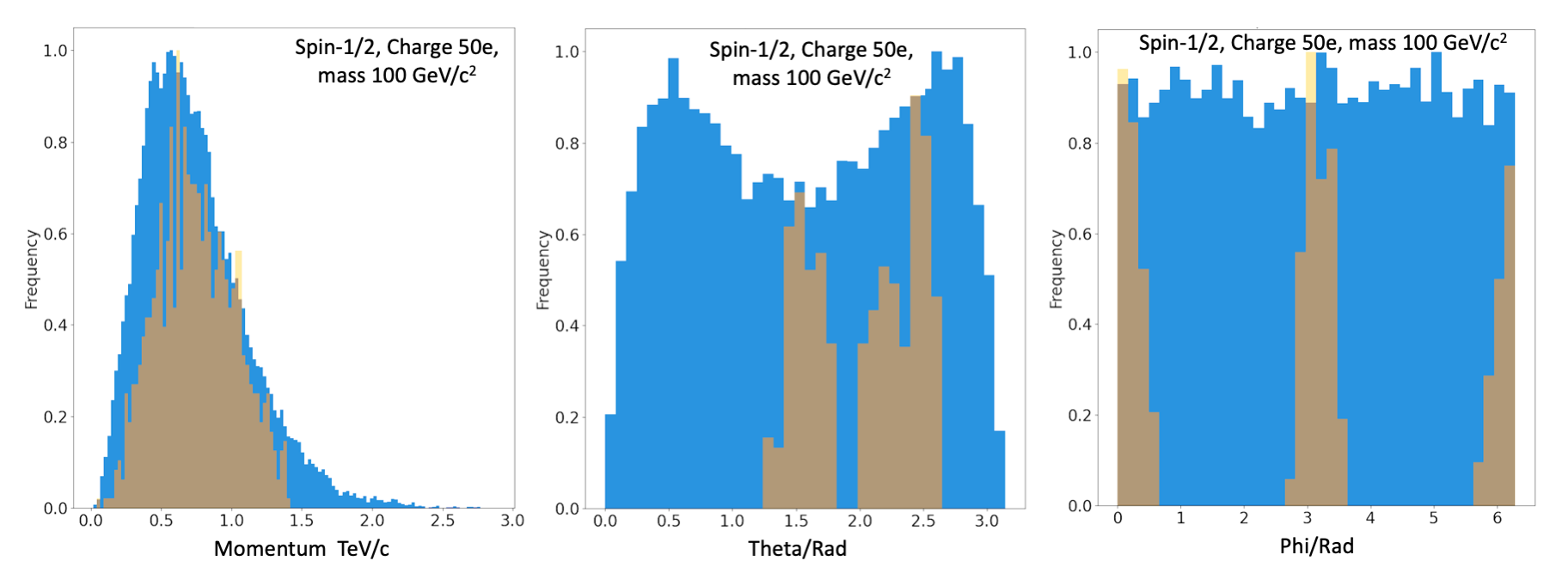
In order to make the comparison clearer, given the large disparity between the number of generated and selected events, each plot was normalized to the the highest amplitude bins as selected by the Freedman - Diaconis rule [62]. As an example we plotted the kinematic variables for DY production of HECOs with mass of 100 GeV/c2 and electric charge 50 are shown in Figure 15, Figure 16 and Figure 17. The corresponding plots for DY production via photon/Z0* exchange, which affects only the spin-1/2 case, are shown in Figure 18.
III Analysis Results
The first Makrofol sheet of each of MoEDAL’s 125 NTD stacks, exposed during LHC’s Run-1 were etched and scanned, as described above, for evidence of the passage through the sheet of a highly ionizing object such as a HECO or a magnetic monopole. The total area of plastic analyzed was 7.8 m2. No candidate events were observed. In addition, no monopole candidates were observed to be trapped in the MMT detector. This is the first time that the data from the full MoEDAL prototype detector, deployed during Run-1, has been presented.
Both the MMTs and the NTDs can be used to detect magnetic monopoles. Consequently, both the NTD and MMT detectors are incorporated into the analysis together. The Run-1 geometric acceptance of MoEDAL’s NTD and MMT detectors did not overlap. Thus, the procedure to combine the monopole signal detected in the NTD and MMT detectors is simple addition. However, only the NTDs can be utilized for the HECO analysis since we have no way to detect electrically charged particles trapped in the MMT detectors.
The dominant source of systematic error in this analysis arises from the imperfect knowledge of the amount of material between the interaction point and the MoEDAL NTD modules, due to LHCb’s VELO detector. The VELO vacuum vessel and the various elements of the VELO detector within LHCb’s physics acceptance are simulated with great precision in the LHCb geometry. However, detailed technical drawings of other elements of VELO outside of the physics acceptance such as cables, in-situ electronics, cooling pipes, various flanges, a vacuum pump and a vacuum manifold, are not available.
Nominally, this intervening material is between 0.1 and 8.0 radiation lengths () in thickness and on average around 1.4 [56] thick. The main contribution to the systematic uncertainty in this analysis arises from the estimate of the material in the Geant4 geometry description. The uncertainty in the material map is modelled by two geometries which represent an excess and a deficit of material, using conservative estimates of uncertainties on material thicknesses and densities, compared to the best assessment of the material budget that is compatible with direct measurement and existing drawings.
This systematic uncertainty in the material map gives rise to uncertainties in the DY acceptances. For singly charge monopoles () the resulting relative uncertainty is of the order of 10% [9]. This uncertainty increases with electric and magnetic charge. For a doubly charged monopoles () it is of the order of 10 - 20% for intermediate masses, around 1 TeV.
Other sources of systematic error are an uncertainty due to a conservative estimate of 1 cm uncertainty in the trapping detector position. Simulations show this error lies in the range 1-17% [9]. Another source of systematics is the uncertainty in as a function of , resulting in a 1-10% relative uncertainty in the acceptance [9].
In the case of monopoles and HECOs a systematic error on the variable , due to the NTD etching and calibration process is given in Fig. 10 (bottom). This error on can give rise to an error on the threshold value for detection of the plastic as well as an error on the variation of efficiency with angle of the NTD. However, these uncertainties are negligible compared to the error on the material map discussed above. All of the above sources of systematic error were added in quadrature and included in the final limit calculation.
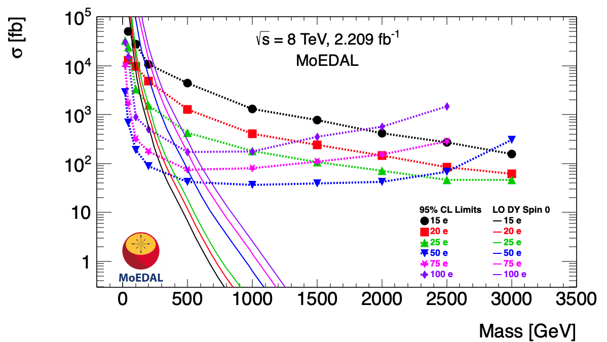
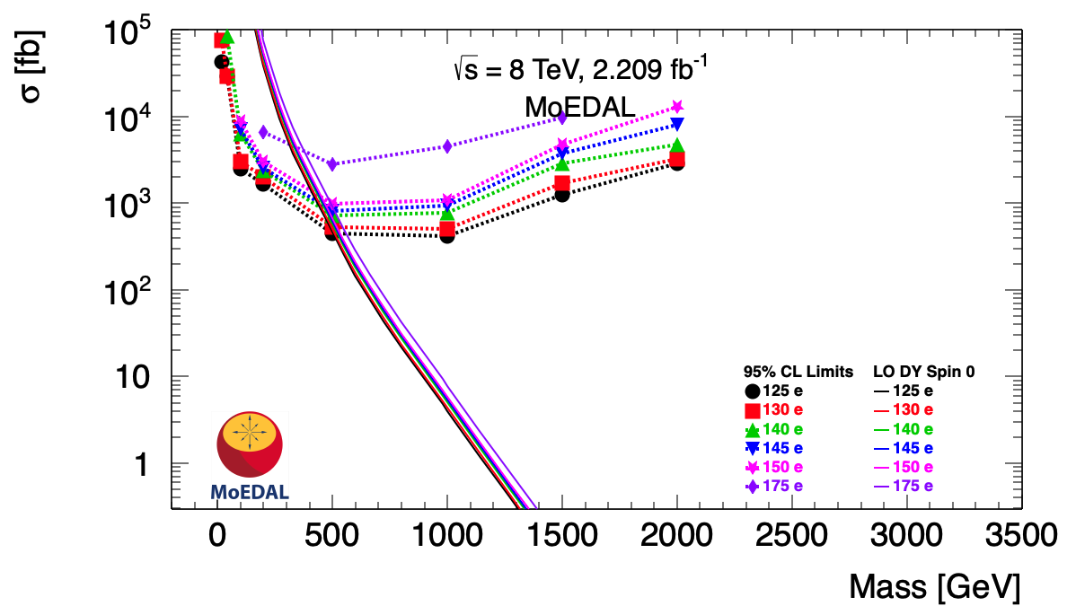
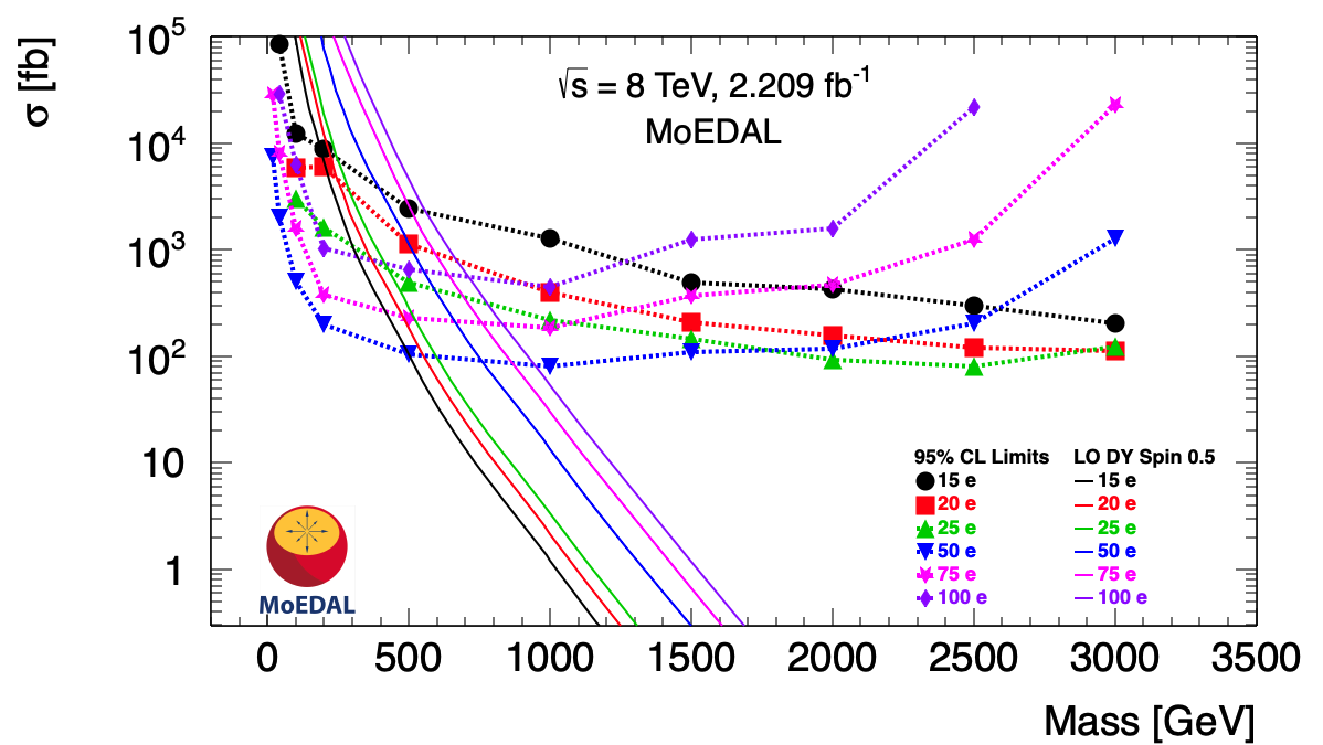
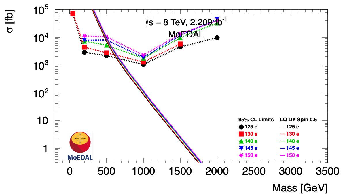
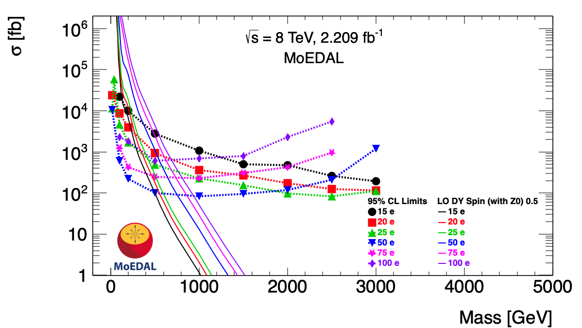
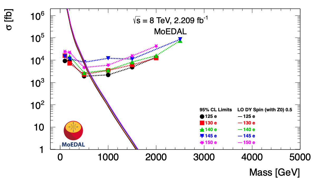
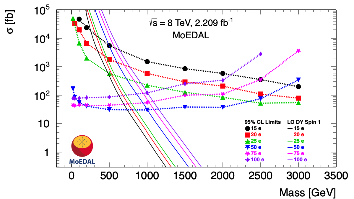
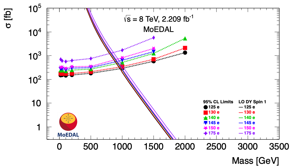
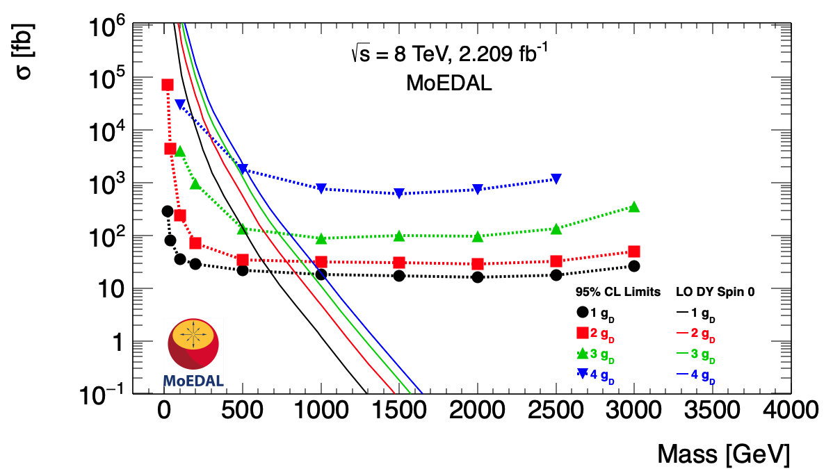
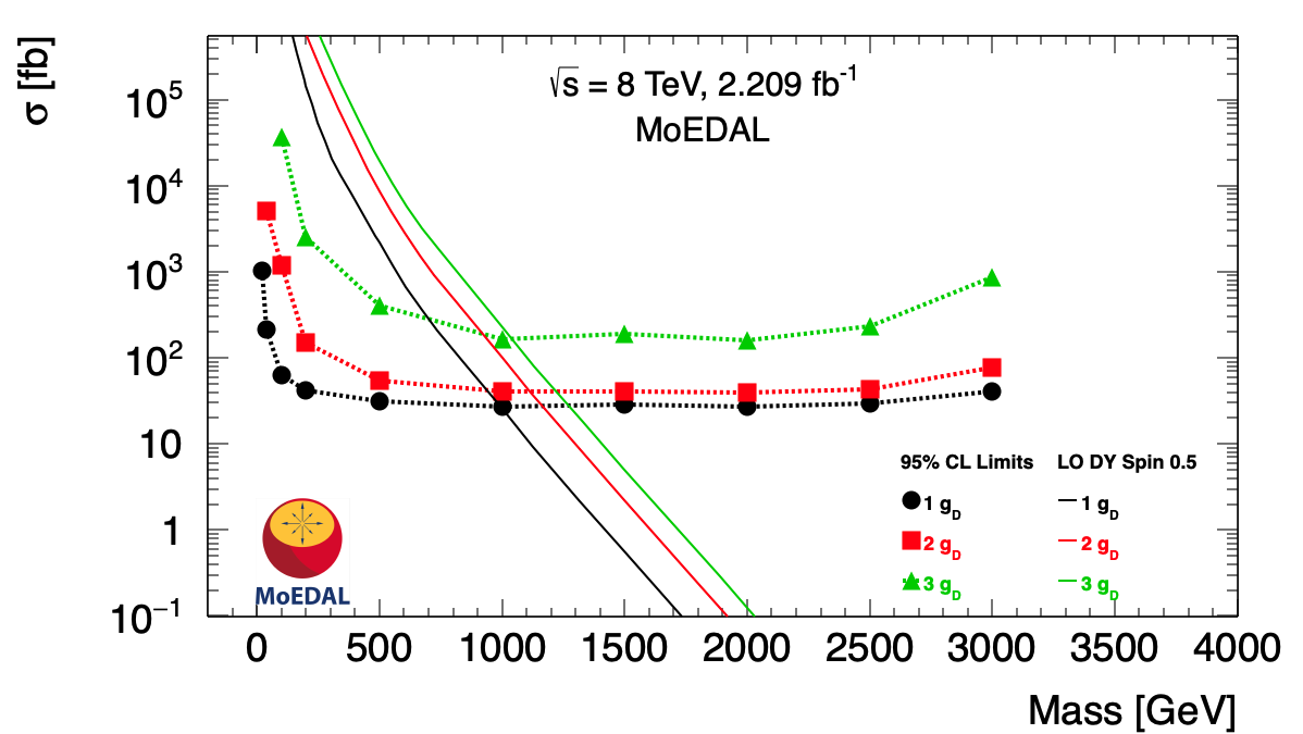
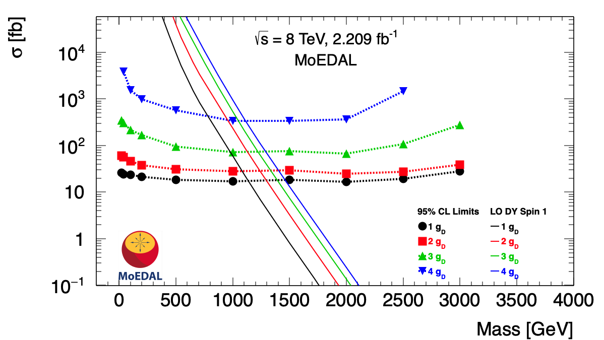
We calculated the 95% C.L. upper limits to the cross-section using as a measure a DY model for HECO and magnetic monopole production assuming a independent monopole coupling and that the monopole can have a spin of and . The limit curves obtained are shown in Fig. 19 for HECOs. The change in trend of the limit curves as the HECO charge goes above 50 is due to the NTD threshold for detection of highly relativistic HECOs that lies at roughly 50. For monopoles the cross-section upper limits versus mass are given in Fig. 20 for spin and . The values of the corresponding 95% C.L. mass limits are listed in Table 2 and Table 3, for HECOs and magnetic monopoles, respectively. In the case of spin-1/2 HECOs we have included exclusive DY production limits, both from combined photon/Z0 exchange and from simply photon exchange. This allows our result to be be compared with the best published charge limit on HECO production prior to this, from the ATLAS Collaboration [16], that considered only DY production of HECOs via photon exchange.
Note that in the spin-1/2 case and at the mass scale explored in this analysis, the cross-section of DY production of HECOs via photon exchange is slightly larger than the DY HECO production cross-section via photon/Z0 exchange, due to destructive interference effects. The convolution of this lower cross-section with the harder momentum spectrum and better acceptance of HECOs produced by DY production via photon/Z0 exchange, results in similar spin-1/2 mass limits to those obtained from HECOs produced by DY production via photon exchange only, over most of the charge range.
| Electric charge (e) | ||||||||||||
| 15 | 20 | 25 | 50 | 75 | 100 | 125 | 130 | 140 | 145 | 150 | 175 | |
| Spin | 95% CL mass limits [GeV/c2] | |||||||||||
| 0 | 70 | 120 | 190 | 560 | 580 | 550 | 500 | 490 | 470 | 470 | 460 | 400 |
| 1/2 (-exchange) | 180 | 280 | 440 | 780 | 780 | 730 | 660 | 640 | 580 | 520 | 500 | - |
| 1/2 (/Z∗-exchange) | 170 | 310 | 440 | 780 | 780 | 710 | 640 | 620 | 620 | 510 | 580 | - |
| 1 | 280 | 430 | 590 | 1000 | 1020 | 1000 | 960 | 950 | 930 | 920 | 900 | 870 |
| Magnetic charge () | ||||
| 1 | 2 | 3 | 4 | |
| Spin | 95% CL mass limits [GeV/c2] | |||
| 0 | 700 | 790 | 750 | 520 |
| 1/2 | 990 | 1110 | 1040 | - |
| 1 | 1140 | 1240 | 1230 | 1110 |
IV Conclusions
Both MoEDAL’s prototype NTD system and aluminium elements of the MoEDAL MMT detector, were exposed to 8 TeV LHC collisions during LHC’s Run-1. At the end of Run-1 both detector systems were examined for the presence of magnetic monopoles and/or HECOs. The NTDs were etched and scanned to reveal evidence for the passage of a magnetic monopole or a HECO using semi-automatic and manual optical microscopes. In the case of the MMT a SQUID-based magnetometer was also utilized to search for the presence of trapped magnetic charge. This is the first time that search results utilizing the NTD detectors are presented.
In previous MoEDAL searches [9] only MoEDAL’s MMT detectors were utilized. Consequently, the HIP search was limited to magnetic monopoles. In this search the use of the NTDs allows the highly ionizing signature of the HIP to be registered. This permits both magnetically charged and electrically charged HIPs (HECOs) to be detected.
No magnetic monopole candidates were found. Consequently, limits on the DY production of magnetic monopole pair with cross-section in the range of approximately 40 fb to 5 pb were set for magnetic charges up to 4 and mass as high as 1.2 TeV/c2. These limits are not competitive with recent Run-2 collider limits [12, 16] despite the use of the NTDs as well as the MMT sub-detectors. This is due to a combination of: the limited acceptance of MoEDAL’s MMT and NTD Run-1 prototype detectors compared to Run-2; the smaller ECM and DY cross-section at Run-1; and, the smaller luminosity of Run-1 compared to Run-2.
No evidence was found for DY produced HECO pairs. Thus, limits were placed on the DY production of HECO pairs with cross-sections from around 30 fb to 70 pb, for electric charges in the range 15e to 175e and masses from 110 GeV/c2 to 1020 GeV/c2. The limits on the DY production of HECOs are the strongest to date, in terms of charge reach, at any collider experiment.
V Acknowledgments
We thank CERN for the LHC’s successful Run-1 operation, as well as the support staff from our institutions without whom MoEDAL could not be operated. We acknowledge the invaluable assistance of particular members of the LHCb Collaboration: G. Wilkinson, R. Lindner, E. Thomas and G. Corti. In addition we would like to recognize the valuable input from W-Y Song and W. Taylor of York University on HECO production processes. Computing support was provided by the GridPP Collaboration, in particular by the Queen Mary University of London and Liverpool grid sites. This work was supported by grant PP00P2_150583 of the Swiss NSF; by the UK Science and Technology Facilities Council, via the grants, ST/L000326/1, ST/L00044X/1, ST/N00101X/1, ST/P000258/1 and ST/T000759/1; by the Generalitat Valenciana via a special grant for MoEDAL and via the projects PROMETEO-II/2017/033 and PROMETEO/2019/087; by MCIU / AEI / FEDER, UE via the grants, FPA2017-85985-P, FPA2017-84543-P and PGC2018-094856-B-I00; by the Physics Department of King’s College London; by NSERC via a project grant; by the V-P Research of the University of Alberta (UofA); by the Provost of the UofA); by UEFISCDI (Romania); by the INFN (Italy); by the Estonian Research Council via a Mobilitas Plus grant MOBTT5; by a National Science Foundation grant (US) to the University of Alabama MoEDAL group; and, by the National Science Centre, Poland, under research grant 2017/26/E/ST2/00135 and the Grieg grant 2019/34/H/ST2/0070.
References
- [1] M. Fairbairn et al., Stable Massive Particles at Colliders, Phys. Rept. 438 (2007).
- [2] L. Patrizii and M. Spurio, Status of Searches for Magnetic Monopoles, Annu. Rev. Nucl. Part. Sci. 65, 279 (2015)
- [3] James Pinfold, MoEDAL Collaboration, Technical Design Report of the MoEDAL Experiment, June 8, 2009, 76 pages Report number: CERN-LHCC-2009-006, MoEDAL-TDR-001
- [4] B. Acharya et al., MoEDAL Collaboration, Physics Programme Of The MoEDAL Experiment At The LHC, Int. J. Mod. Phys. A29, 1430050 (2014).
- [5] G. Aad et al., ATLAS Collaboration, Search for massive long-lived highly ionizing particles with the ATLAS detector at the LHC, Phys. Lett. B 698, 53 2011.
- [6] G. Aad et al., ATLAS Collaboration, Search for Magnetic Monopoles in = 7 TeV pp Collisions with the ATLAS Detector, Phys. Rev. Lett. 109, 261803 (2012),
- [7] G. Aad et al., ATLAS Collaboration, Search for long-lived, multi-charged particles in pp collisions at = 7 TeV using the ATLAS detector, Phys. Lett. B 722, 305 (2013).
- [8] G. Aad et al, ATLAS Collaboration, Search for magnetic monopoles and stable particles with high electric charges in 8 TeV pp collisions with the ATLAS detector, Phys. Rev. D 93, 052009 (2016).
- [9] B. Acharya et al., MoEDAL Collaboration, Search for magnetic monopoles with the MoEDAL prototype trapping detector in 8 TeV proton-proton collisions at the LHC, JHEP 08, 067 (2016).
- [10] B. Acharya et al., MoEDAL Collaboration, Search for magnetic monopoles with the MoEDAL forward trapping detector in 13 TeV proton-proton collisions at the LHC, Phys. Rev. Lett. 118, 061801 (2017).
- [11] B. Acharya et al., MoEDAL Collaboration, Search for magnetic monopoles with the MoEDAL forward trapping detector in 2.11 fb-1 of 13 TeV proton-proton collisions at the LHC, Phys. Lett. B 782, 510 (2018).
- [12] B. Acharya et al., MoEDAL Collaboration, Magnetic Monopole Search with the Full MoEDAL Trapping Detector in 13 TeV pp Collisions Interpreted in Photon-Fusion and Drell-Yan Production, Phys.Rev.Lett. 123, 021802 (2019).
- [13] ATLAS Collaboration, Search for heavy long-lived multi-charged particles in pp collisions at = 8 TeV using the ATLAS detector, Eur. Phys. J. C 75, 362 (2015).
- [14] S. Chatrchyan et al., CMS Collaboration, Searches for long-lived charged particles in pp collisions at = 7 and 8 TeV, JHEP 07, 122 (2013) 122.
- [15] M. Aaboud, ATLAS Collaboration, Search for heavy long-lived multi-charged particles in proton-proton collisions at = 13 TeV using the ATLAS detector, Phys. Rev. D 99, 052003 (2018) 052003.
- [16] G. Aad et al., The ATLAS Collaboration, Search for Magnetic Monopoles and Stable High-Electric Charged Objects in 13 TeV Proton-Proton Collisions with the ATLAS Detector, Phys. Rev. Lett., 124, 3 031802 (2020).
- [17] Nick E. Mavromatos, Vasiliki A. Mitsou, Magnetic monopoles revisited: Models and searches at colliders and in the Cosmos, Int. J. Mod. Phys. A 35 (2020) 23, 2030012 e-Print: 2005.05100 [hep-ph] DOI: 10.1142/S0217751X20300124.
- [18] L. Patrizii, Z. Sahnoun, and V. Togo, Searches for cosmic magnetic monopoles: past, present and future, Phil. Trans. R. Soc. A 377: 20180328 (2019).
- [19] S. Burdin et al., Non-collider searches for stable massive particles, Phys. Rept. 582, 1(2015).
- [20] J. Beringer et al. (Particle Data Group), Phys. Rev. D86, 0100001 (2012).
- [21] D. Felea et al., Prospects for discovering supersymmetric long-lived particles with MoEDAL, Eur. Phys. J. C 80 5, 431 (2020).
- [22] B. S. Acharya et al., MoEDAL Collaboration, Prospects of searches for long-lived charged particles with MoEDAL, Eur. Phys. J. C. 80 6, 572 (2020).
- [23] P. A. M. Dirac, Quantised Singularities in the Electromagnetic Field, Proc. Roy. Soc.A 133, 60 (1931).
- [24] G. ’t Hooft,Magnetic Monopoles in Unified Gauge Theories, Nucl. Phys. B79, 276 (1974).
- [25] A. M. Polyakov, Particle Spectrum in the Quantum Field Theory, JETP Lett.20, 194 (1974).
- [26] H. Georgi and S. Glashow, Unified weak and electromagnetic interactions without neutral currents. Phys. Rev. Lett, 28, 1494 (1972).
- [27] H. Georgi and S. Glashow, S. Unity of all elementary particle forces. Phys. Rev. Lett, 32, 438–441 (1974).
- [28] Y.M. Cho and D. Maison, Phys. Lett.B391, 360 (1997).
- [29] W.S. Bae and Y.M. Cho, JKPS46, 791 (2005).
- [30] Y. M. Cho, K. Kim and J. H. Yoon, Eur. Phys. J. C75, no. 2, 67 (2015).
- [31] J. Schwinger, A Magnetic Model of Matter. Science. 165, 757-761 (3895).
- [32] P. Q. Hung, “Topologically stable, finite energy electrweak-scale monopoles”, Nucl. Phys. B962, 115278 (2021).
- [33] J. Elllis, P. Q. Hung and N. Mavromatos, “ An Electroweak Monopole, Dirac Quantization and the Weak Mixing Angle”, Nucl. Phys. B 969 (2021) 115468 DOI: 10.1016/j.nuclphysb.2021.115468; arXiv:2008.00464[hep-ph], (2020).
- [34] Kurochkin, I. Satsunkevich, D. Shoukavy, N. Rusakovich, Y. Kulchitsky, “On Production of Magnetic Monopoles via Fusion at High Energy p-p Collisions,” Mod. Phys. Lett. A 21, 2873 (2006).
- [35] Y. Kurochkin, Y. Kulchitsky, I. Satsunkevich, D. Shoukavy, V. Makhnatch, N. Rusakovich, Modern status of magnetic monopoles (2007) (unpublished)
- [36] S. Baines, N. E. Mavromatos, V. A. Mitsou, J. L. Pinfold, A. Santra, “Monopole production via photon fusion and Drell-Yan processes: MadGraph implementation and perturbativity via velocity-dependent coupling and magnetic moment as novel features,” Eur. Phys. J. C 78, 966 (2018).
- [37] T.D. Lee, C.N. Yang, “Theory of Charged Vector Mesons Interacting with the Electromagnetic Field,” Phys. Rev. 128, 885 (1962).
- [38] J. Ellis, N. E. Mavromatos, T. You, The Price of an Electroweak Monopole, Phys. Lett. B756, 20-35 (2016).
- [39] M. Hirsch, R. Maselek and K. Sakurai, Detecting long-lived multi-charged particles in neutrino mass models with MoEDAL Eur. Phys. J. C 81 (2021) 8, 697; e-Print: 2103.05644 [hep-ph] DOI: 10.1140/epjc/s10052-021-09507-9.
- [40] B. Holdom, J. Ren, and C. Zhang, Quark Matter May Not Be Strange, Phys. Rev. Lett. 120, 222001 (2018).
- [41] E. Farhi and R. Jaffe, Strange matter, Phys. Rev. D30, 2379 (1984).
- [42] S. Coleman,Q-balls, Nucl. Phys. B262, 263 (1985).
- [43] A. Kusenko and M. E. Shaposhnikov, Supersymmetric Q-balls as dark matter, Phys. Lett. B418(1998) 46.
- [44] B. Koch, M. Bleicher, and H. Stöcker,Black holes at LHC? J. Phys. G34 S535 (2007).
- [45] A. Aaij et al., The LHCb Collaboration, “Precision luminosity measurements at LHCb”, JINST 9, P12005 (2014).
- [46] W-Y Song and W. Taylor, “Pair production of magnetic monopoles and stable high-electric-charge objects in proton-proton and heavy-ion collisions,” arXiv:2107.10789v1 [hep-ph] 22 Jul 2021.
- [47] C. D. Roberts and A. G. Williams,“Dyson-Schwinger equations and their application to hadronic physics,” Prog. Part. Nucl. Phys. 33, 477-575 (1994).
- [48] D. Binosi and J. Papavassiliou, “Pinch Technique: Theory and Applications,” Phys. Rept. 479, 1-152 (2009)
- [49] E. V Benton and W. D. Nix, The restricted energy loss criterion for registration of charged particles in plastics, NIM 67, 343-347 (1969).
- [50] L.P. Gamberg, G.R. Kalbfleisch and K.A. Milton, Direct and indirect searches for low mass magnetic monopoles, Found. Phys. 30, 543 (2000) 543; Private communication from Kimball A. Milton, January 26th 2021.
- [51] C.J. Goebel, Binding of nuclei to monopoles, in Monopole ’83, J.L. Stone ed., Plenum(1984), p. 333.
- [52] L. Bracci and G. Fiorentini, Interactions of Magnetic Monopoles With Nuclei and Atoms, Nucl. Phys. B 232, 236 (1984).
- [53] K. Olaussen and R. Sollie, Form-factor effects on nucleus-magnetic monopole binding, Nucl.Phys.B 255, 465 (1985).
- [54] A. De Roeck et al., Development of a magnetometer-based search strategy for stopped monopoles at the Large Hadron Collider, Eur. Phys. J. C72,2212 (2012).
- [55] S. Balestra et al., Bulk etch rate measurements and calibrations of plastic nuclear track detectors, NIM-B 254, 254-258 (2007).
- [56] A. A. Alves Jr., et al., LHCb Collaboration, The LHCb Detector at the LHC, JINST 3, S08005 (2008).
- [57] L. A. Harland-Lang, V. A. Khoze and M. G. Ryskin, “Exclusive LHC physics with heavy ions: SuperChic 3,” Eur. Phys. J. C 79, no.1, 39 (2019) doi:10.1140/epjc/s10052-018-6530-5 [arXiv:1810.06567 [hep-ph]].
- [58] P.J.W.Faulkner et al.,GridPP: development of the UK computing Grid for particle physics, Journal of Physics G: Nuclear and Particle Physics, 32(1), N1-N20 (2006)
- [59] D. Britton et al., GridPP: The UK grid for particle physics, Phil. Trans. R. Soc. 367(1897):2447-57 (2009)
- [60] M. Ambrosio et al., MACRO Collaboration, Eur. Phys. J. C25 511 (2002).
- [61] S. Balestra et al., The SLIM Collaboration, Magnetic Monopole Search at high altitude with the SLIM experiment, Eur. Phys. J.C 55, 57-63 (2008).
- [62] D. Freedman and P. Diaconis, Persi (December 1981). “On the histogram as a density estimator: L2 theory”. Probability Theory and Related Fields. 57 (4), 453-476 (1981).