An Improved Fractional-Order Active Disturbance Rejection Control: Performance Analysis and Experiment Verification
Bolin Li, Lijun Zhu,
Bolin Li is with Key Laboratory of Imaging Processing and Intelligence Control, School of Artificial Intelligence and Automation, Huazhong University of Science and Technology, Wuhan 430074, China.Lijun Zhu is with Key Laboratory of Imaging Processing and Intelligence Control, School of Artificial Intelligence and Automation, Huazhong University of Science and Technology, Wuhan 430074, China.
Abstract
This paper presents an improved active disturbance rejection control scheme (IFO-ADRC) with an improved fractional-order extended state observer (IFO-ESO).
The structural information of the system is utilized in IFO-ESO rather than buried as in the typical fractional-order extended state observer (FO-ESO) and help significantly improve the performance of IFO-ESO and closed-loop system. Compared with the integer-order active disturbance rejection controller (IO-ADRC), the auxiliary tracking controller of IFO-ADRC has a simpler form and fewer parameters need to be tuned. Frequency-domain analysis shows that IFO-ESO has better performance over the larger frequency band than FO-ESO, and time-domain simulation shows that IFO-ADRC has better transient performance and is more robust against the parameter variations than traditional fractional-order active disturbance rejection controller (FO-ADRC) and IO-ADRC. The IFO-ADRC is applied to permanent magnet synchronous motor (PMSM) servo control system and demonstrates its capability in the real-world application.
Index Terms:
Active disturbance rejection control, fractional-order active disturbance rejection control, fractional-order extended state observer, robustness.
I Introduction
Fractional calculus has been applied to different fields in recent years [1, 2, 3, 4]. With a deep understanding of the system, there is a growing need for fractional-order control and modelling [5, 6]. Some real-world phenomena demonstrate fractional-order characteristics [7, 8]. Permanent magnet synchronous motor [8], gas-turbine [9], and heating–furnace [10] can be identified as fractional-order models. On the other hand, the fractional-order controller has the potential to achieve better and more robust control performance than the integer-order controller [11]. Many fractional-order controllers have been proposed, including fractional-order sliding mode controller [12, 13], fractional-order intelligent PID controller [14], fractional-order PID controller [15], and so on.
The active disturbance rejection control (ADRC) was proposed in [16] as an alternative paradigm for control system design. The core idea of ADRC is to improve the robustness of the system using extended state observer (ESO). ESO, an important part ADRC, can estimate the total disturbances, including internal disturbance caused by system uncertainties and external disturbance. Gao [17] proposed the linear ADRC to broaden the application range of ADRC by linearizing ESO (IO-ESO) and feedback control law. Applying IO-ESO, a -order integer-order system can be approximately converted into unit gain integer-order integrators in series. According to the design idea of the linear IO-ADRC, a linear feedback control law of parameters need to be designed to realize the stable closed-loop system. Furthermore, Gao [18] proposed an ADRC structure involving the fractional-order tracking differentiator, the fractional-order PID controller and the fractional-order extended state observer for nonlinear fractional-order systems. The stability region of the fractional-order system can be larger than that of the integer-order system in the complex plane [19]. FO-ADRC can provide a possibility to realize closed-loop stability with a simpler controller. In [1], Chen et al. applied FO-ESO to approximately convert a typical second-order system into a cascaded fractional-order integrator and the stable closed-loop system can be realized using merely a simple proportional controller. For a fractional-order system, it is natural to use a fractional-order controller to achieve closed-loop stability [20, 21]. A FO-ADRC based on FO-ESO was proposed by Li [22] to approximately convert the fractional-order system to a cascaded fractional-order integrator.
The IO-ADRC was proved by Li [23] to estimate the disturbances in fractional-order systems, which considers the fractional-order dynamics as a common disturbance.
An integer-order system can be approximately converted to a fractional-order system (a cascaded fractional-order integrator) by using FO-ESO and then an auxiliary tracking controller is designed to meet the actual needs [1]. However, the
satisfactory approximation can only be made
in the low-frequency band, making it difficult to ensure the system’s robustness when the control system bandwidth is large.
This paper is along the research line of proposing a new type of fractional-order ESO structure and then fractional-order ADRC. The main contributions of the paper can be summarized as follows. First, the new type of ESO, called IFO-ESO, will utilize structural information in the total disturbance given in FO-ESO. IFO-ESO will be used to compensate for the system uncertainties and external disturbance. The compensated system is approximately converted into a fractional-order integrator. It will be shown that
the approximation performance is improved by IFO-ESO over FO-ESO, making the system more robust to system uncertainties and external disturbances. The theoretical analysis is verified by the control experiment on the PMSM servo speed control system. Second, compared with IO-ADRC, the auxiliary tracking controller of IFO-ADRC has a simpler form and fewer parameters need to be tuned. Thirdly, the stability criteria of the IFO-ESO and the IFO-ADRC closed-loop system are given when the disturbance is assumed to be bounded. Unlike the stability analysis of the ESO and the closed-loop system in [1] and [22], the stability criteria of the high-order ESO and high-order ADRC closed-loop system in this paper are given.
This paper is organized as follows. The structures of IFO-ESO and IFO-ADRC are proposed in Section II. The BIBO stability criteria of the IFO-ESO and the closed-loop system are given in Section III. The performance analysis of the IFO-ESO in the frequency-domain is shown in Section IV. Section V presents the time-domain simulation results, followed by the experimental results on PMSM servo system in VI. The paper is concluded in Section VII.
Notations. is an identity matrix and is an zero vector matrix with size specified by the subscript.
II An improved Structure of Active disturbance rejection controls
In this paper, we consider an integer-order linear system as follows:
(1)
where is Laplace operator, , and are real numbers, and are positive integers with representing the maximum order of the system.
The differential equation form of system (1) with the external disturbance, denoted by , is
(2)
Caputo derivative is adopted as the fractional-order derivative method in this paper and described as follows,
(3)
where is an integer satisfying and is a real number, is Euler’s gammafunction. From the adopted definition, one can see that where is a positive number [24].
Let be a fractional number satisfying , be a positive integer number satisfying , and be a fractional number. As a result, .
Define the quantity . Equation (2) can be rewritten as follows,
(4)
Note that can be regarded as the total disturbance where the term is the internal disturbance due to uncertain parameters and is the external disturbance. The aim of this paper is to design such that the system output tracks a sufficiently smooth reference trajectory and the ultimate tracking error stays in the neighborhood of the origin, i.e., , when the reference signal and its derivatives, i.e., , , are bounded.
As inspired by FO-ADRC in [1], we propose the tracking controller as follows
(5)
where
and are estimators for signals and , respectively, and
is the auxiliary tracking controller to be specified later.
If signals and are approximately estimated by and , the closed-loop system composed of (4) and (5) can be approximately converted into a fractional-order integrator as follows
(6)
As will be explained in Remark II.2, a big advantage of IFO-ADRC and FO-ADRC is that a simpler auxiliary controller can be designed and easily tuned.
where the term = . In comparison to FO-ADRC, IFO-ADRC will separate the structurally certain term from . It is explicitly included in (4) and estimated in a new type of ESO introduced later. As will be demonstrated in Section IV and V, the structural certainty of the term can help significantly improve the performance of ESO and the closed-loop system.
Let where represent system states and is an extended state, the state-space representation of (4) is given as follows:
(8)
where
(11)
(14)
(17)
Then, IFO-ESO is designed to estimate as follows:
(18)
where
(20)
(22)
(23)
Note that are extended state observer gains. are the estimation of the state , respectively and is the nominal value of . Let in (5) be
With IFO-ESO, the tracking task can be fulfilled with
the auxiliary tracking controller in (5), which is designed as follows,
(24)
where are the parameters of the feedback control law. The closed-loop system composed of (2), (5) and (24), is called IFO-ADRC system.
where = . Any part of controller similar to (5) where the auxiliary tracking controller is designed as
(25)
Note that the number of parameters for the auxiliary tracking controller of IFO-ADRC is less than that of IO-ADRC.
In other words, we can achieve the trajectory tracking for an integer-order plant with a simpler auxiliary controller process, which simplifies the parameter tuning.
As will be demonstrated in Section V, a P auxiliary tracking controller can be adopted to achieve the trajectory tracking of a second-order integer-order plant, and a PD auxiliary tracking controller can be adopted for a third-order integer-order plant.
Section V will show the system transient performance of IFO-ADRC is better than that of IO-ADRC.
III Stablilty analysis of IFO-ADRC
In this section, the stability criteria for the ESO and the IFO-ADRC system are provided.
Let the observer error be
(26)
From (8) and (18), the equation of the extended state observer error can be written as
(27)
where .
The characteristic matrix of (27) is [25]:
(28)
From (28), the characteristic polynomial of the system (27) can be obtained:
(29)
where and .
Then,
Theorem III.1 will present the bounded-input bounded-output (BIBO) stability of the error system (27), when is bounded. If the boundedness of the external disturbance rather than is assumed, Theorem III.2 will give the condition of BIBO stability of the closed-loop system in terms of roots of a polynomial. In this case, the tracking error converges into a neighborhood of the origin.
A special case of Theorem III.2 when is elaborated in Proposition III.1, showing that when the observer gain is selected sufficiently large, the system is BIBO.
The proofs of both theorems and the proposition are given in the Appendix.
Theorem III.1
Consider the error dynamics of IFO-ESO (27). Let and for . If is bounded, then the IFO-ESO is BIBO stable, regarding as the input and as the output.
Theorem III.2
Consider the IFO-ADRC closed-loop system composed of (2), (5) and (24). Let , , , and positive prime such that and . Define a polynomial
(30)
If , and are selected such that all the roots of (30) are located in , then the IFO-ADRC closed-loop system is BIBO stable,
Moreover, the tracking error converges to a small neighborhood of the origin as .
Proposition III.1
Consider the IFO-ADRC closed-loop system composed of (2), (5) and (24) with
. Suppose the plant
(2) is stable or marginally stable, i.e., and .
Let for , . Then, there always exists a constant , such that the closed-loop system is BIBO stable.
Moreover, the tracking error converges to a small neighborhood of the origin as .
IV Performance Analysis of IFO-ESO in Frequency- domain
In this section, we will compare the performance of the IFO-ESO proposed in Section II with the FO-ESO proposed in [1].
The FO-ESO is as follows
(31)
where , , , and are given in (23).
Similar to the analysis in Section II, the controller utilizing the estimation of the FO-ESO in [1] is
(32)
which is aimed to approximately convert the perturbed system into a pure cascaded integrator shown as follows
(33)
Note that the role of the ESO in the framework of ADRC including IO-ESO, FO-ESO and IFO-ESO is to estimate the uncertain dynamics and external disturbances to improve the robustness of the system.
If the IFO-ESO can perfectly estimate and or the FO-ESO can perfectly estimate ,
the IFO-ADRC in (5) and the FO-ADRC in (32) can convert the original system into a cascaded fractional-order integrator (looking from to ).
Therefore, we are motivated to use the model difference between and to assess the performance of the two ESO.
We adopt mean square error between and in the frequency-domain to evaluate how difference the two models are. The mean square error (MSE) of two linear model is defined as
(34)
where
(35)
The MSE (34) was used in [26] for the model identification where the problem is re-casted into an optimal problem of minimizing the model difference between the identified and ideal model in terms of the MSE. Therefore, the MSE can be used to evaluate model difference in the frequency-domain.
As in [1], for simplicity, we consider the second-order system as follow
(36)
where the external disturbance and system uncertainty are not considered.
In this case, the FO-ESO in (31) is simplified
with
(40)
(43)
Similarly, the IFO-ESO is
(44)
where .
Next, let us calculate for FO-ADRC and IFO-ADRC.
For the fair comparison, we choose the same group of the observer gains , , for IFO-ESO and FO-ESO.
For the IFO-ESO, all the parameters meet the conditions of Theorem III.1, and thus the dynamics of the estimation error for IFO-ESO is asymptotically stable (because the disturbance and uncertainties do not exist). Conducting the Laplace transform on the both sides of (44) gives
(45)
where , , , and are the Laplace transforms of signals , , , and , and the quantity , respectively.
Conducting the Laplace transform on the both sides of (5) and substituting the result and (45) into (36) obtain
(46)
where
(47)
Similarly, the Laplace transform of the both side of FO-ESO (31) gives
(48)
Conducting the Laplace transform on the both sides of (32) and substituting the result and (48) into (36) obtain
(49)
where
(50)
The model difference between the fractional-order integrator and ( or ) at can be expressed as:
(51)
Then, the mean-square error between the fractional-order integrator and can be expressed as follows:
(52)
where
(53)
From (34) and (49), the mean-square error between the fractional-order integrator and can be expressed as follows:
(54)
where
(55)
Now, let us use the Bode diagram to study the performance of FO-ESO and IFO-ESO with observer gains . Moreover, the system parameters and the observer gain parameters are adapted from [1], i.e.,
, , and . The Bode diagram of in (46) and in (49) are illustrated in Fig. 1.
Figure 1: Bode diagram of the model : in (46) with IFO-ESO; in (49) with FO-ESO.
It is clearly shown in Fig. 1 that the amplitude and the phase diagram of are close to that of within a larger fequency band than that of are. In particular, the approximation of to gets worse in high-frequency band. Fig. 2 shows the mean-square error and with respect to frequency . The result coincides with Fig. 1 that better approximates the integrator than does. In other words, the IFO-ESO has better performance in terms of disturbance estimation than the FO-ESO. Therefore, the closed-loop system resulting from the IFO-ESO is more robust than that from the FO-ESO.
Figure 2: The MSE curves when , , and
Fig. 3 shows the curves of the mean-square error and with different model paramter when and . Fig. 4 shows the curves of the mean-square error and with different observer gains when and . Fig. 5 demonstrates the variation of the mean-square error with different order when and . As shown in Fig. 3, Fig. 4, and Fig. 5, the mean-square error is less prone to the variation of system parameter , controller parameters , and the order than the mean-square error is.
Figure 3: The MSE curves with different when = 2000 and = 0.75Figure 4: The MSE curves with different when = 10 and = 0.75Figure 5: The MSE curves with different when = 10 and = 2000
Remark IV.1
Note that if the performance of ESO is robust to the variation of the closed-loop system parameters , , and , the auxiliary tracking controller design of based on the compensated system (6) or (33)
can achieve better performance when these parameters vary. In other words, the IFO-ADRC closed-loop system is more robust with respect to the variations of the plant parameters and ESO parameters.
V Time-domain simulation and Comparison
In this section, we will show the performance of the IFO-ADRC in the time-domain using MATLAB/Simulink and compare it with IO-ADRC and FO-ADRC. The plant used for the simulation is (36) which is adopted from the example of [1].
The structures of IFO-ADRC, FO-ADRC and IO-ADRC are similar and presented in Fig. 6, 7 and 8, respectively.
An advantage of IFO-ADRC and FO-ADRC is that a simpler auxiliary controller can be used.
Note that the auxiliary controller for IFO-ADRC and FO-ADRC is a P controller, while PD controllers must be used in IO-ADRC to ensure the stability.
The controller in IFO-ADRC and FO-ADRC is
(56)
where
is the parameter of P controller
and the PD controller in IO-ADRC is
(57)
where and are the PD parameters. The IO-ESO used in IO-ADRC is given [17],
(58)
Refer to (43) for the matrices , , , and . The controller in IO-ADRC is given
(59)
Figure 6: Structure of the IFO-ADRCFigure 7: Structure of the FO-ADRC in [1]Figure 8: Structure of the IO-ADRC
The observer gains and the order are adopted from the reference paper [1], i.e., , , , rad/s, and . The fractional-order operator is discretized by the impulse response invariant method [27] where the discrete frequency for IFO-ESO and FO-ESO is 8000 Hz and the discrete order of the fractional-order operators is 7. Let the P controller parameter be . Note that
the observer parameters satisfy conditions of Theorem III.2 and Theorem 1 in [1], the IFO-ADRC and FO-ADRC closed-loop systems are BIBO stable.
For the fair comparison, based on the open-loop transfer function, the PD controller used in IO-ADRC parameters are chosen to ensure that the gain crossover frequency and the phase margin of the IO-ADRC are the same as that of the IFO-ADRC [1, 11]. For IFO-ADRC, the open-loop transfer function can be described as
(60)
where
(61)
The gain crossover frequency = 42 rad/s and the phase margin
can be calculated from
(62)
For IO-ADRC, the open-loop transfer function is
(63)
where
(64)
Then, the PD controller for IO-ADRC can be designed as
(65)
to ensure that the gain crossover frequency rad/s and the phase margin
The open-loop Bode diagram of the IO-ADRC and IFO-ADRC systems is illustrated in Fig. 9 showing that the two systems have the same gain crossover frequency = 42 rad/s and phase margin . From the open-loop Bode diagram of the IO-ADRC system, the IO-ADRC closed-loop system is stable.
Figure 9: Open-loop Bode diagram of the IO-ADRC system and the IFO-ADRC systemTABLE I: Comparison of the responses with three control systems (simulation)
The step responses of the IO-ADRC, FO-ADRC, and IFO-ADRC systems are shown in Fig. 10. It is shown in Fig. 10 that the IFO-ADRC system has better dynamic response performance than the FO-ADRC and IO-ADRC systems. The IFO-ADRC system has smaller overshoot than the FO-ADRC system.
Now, let us consider the system performance variation against controller parameters. Let us multiple the P controller parameter and PD controller parameter
by and . The nominal value is used when .
Fig. 11, Fig. 12 and Fig. 13 are the step responses of three closed-loop systems when different controller parameters are imposed. As shown in Fig. 12 and Fig. 13, the IFO-ADRC system are robust to controller gain variations.
When , , or are set respectively, the maximum speed of the step response are denoted as . The overshoot fluctuation is calculated as
overshoot fluctuation =
(66)
The step responses of three closed-loop systems for different are given in TABLE I. Note that the overshoots of IFO-ADRC system and the IO-ADRC system are similar and smaller than that of the FO-ADRC system. The settling time of the IFO-ADRC system is shorter than the IO-ADRC and FO-ADRC systems.
Figure 10: Step responses of three differemt control systemsFigure 11: Step responses of the IO-ADRC control system with controller gain variationsFigure 12: Step responses of the FO-ADRC control system with controller gain variationsFigure 13: Step responses of the IFO-ADRC control system with controller gain variations
VI Experiments: PMSM speed servo control
In the section, the control performance of IFO-ADRC, FO-ADRC, and IO-ADRC are compared in a real-world application. Experiments are carried out on the PMSM speed servo control system. Fig. 14 is the block diagram of the PMSM given in -axis frame. The diagram encircled by
the blue and red dotted lines are the electromagnetic and the mechanical part of the PMSM, respectively.
Figure 14: Mathematical model of the PMSM
The armature current of DC motor can be represented by -axis component of the current [8]. The -axis voltage equation of PMSM is described as follows
(67)
where is the -axis voltage, is the back
electromotive force, is the electromotive force coefficient, is the actual speed of motor rotor, is motor phase armature resistance, is -axis current and is -axis inductance.
Taking as the input voltage and as the output current, the transfer functions of the electromagnetic part is
(68)
where and are the Laplace transforms of and , respectively.
Note that is regarded as a constant disturbance input of the -axis current loop and is therefore not shown in the transfer function above [28].
The motion equation of PMSM can be described as follows
(69)
where is the electromagnetic moment, is the load moment, is the torque coefficient, is the equivalent current of load torque, is flywheel inertia, is a speed conversion factor, is coefficient of viscous friction, and is the actual speed of the motor rotor.
Taking as input current and as output speed, the transfer functions of the mechanical part is
(70)
where is the Laplace transforms of .
Note that the load moment is not considered in this paper, i.e., ,
(a)Current loop of the PMSM speed servo system(b) Speed loop of the PMSM speed servo system
Figure 15: PMSM speed servo system using IFO-ADRC
The block encircled by the green dash-dotted line in Fig. 15(a) is the block diagram of the current loop of the PMSM speed servo system. In Fig. 15(a), and are the per unit of the actual voltage and the actual current, respectively, is the reference input of the current loop, and are the voltage and current conversion factors, respectively. The PI controller in current loop is designed to ensure that in the operating frequency band of the speed loop. Fig. 15(b) is the block diagram of the speed loop of the PMSM speed servo system using IFO-ADRC. In Fig. 15(b), is the speed conversion factor, is the speed feedback filter coefficient, and is the per unit of the actual speed.
Since , thus the plant of the speed loop is
(71)
where and are Laplace transforms of and , respectively.
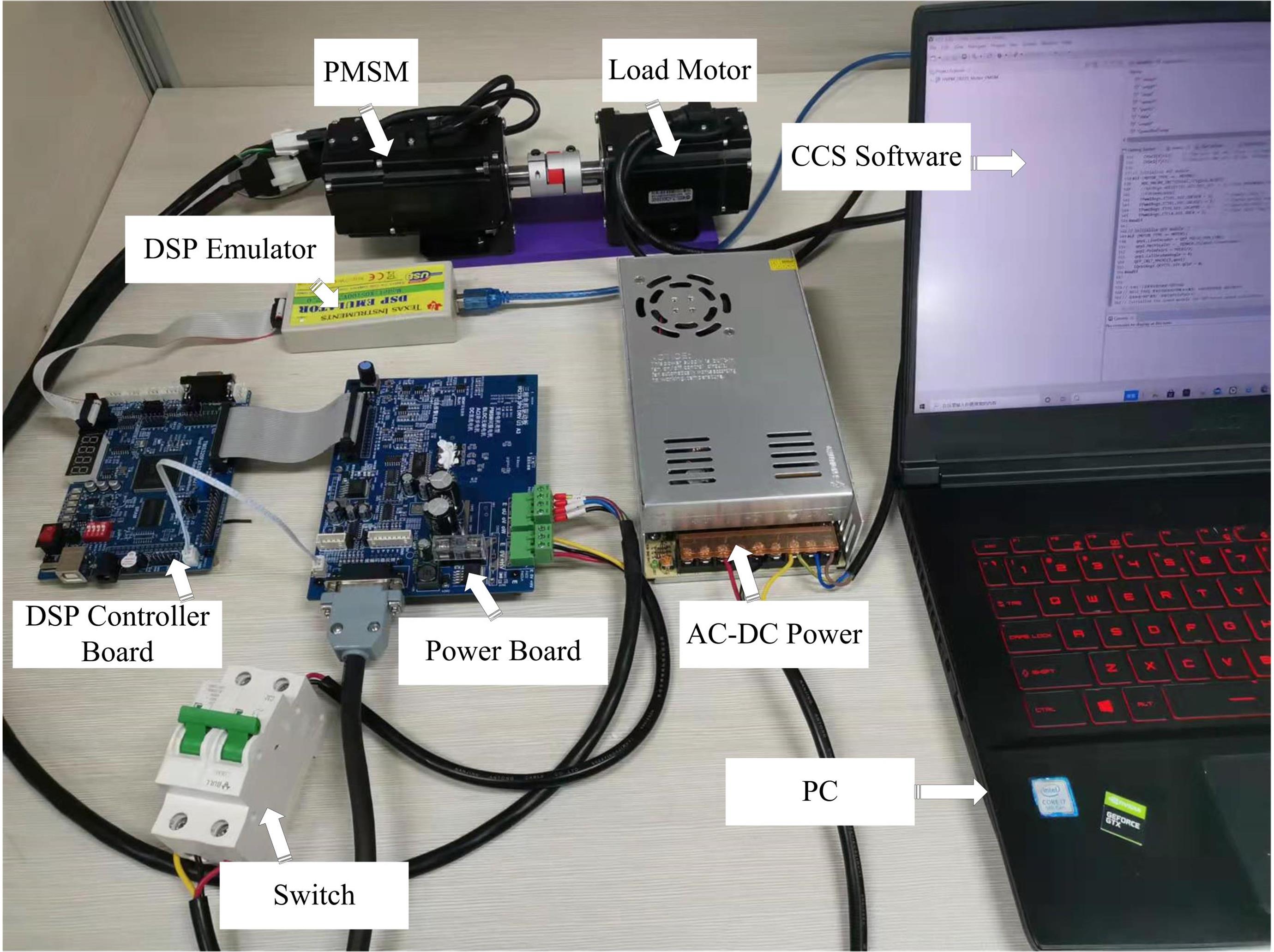
The closed-loop controller is implemented on digital signal processor (DSP) illustrated in Fig. 16. The PMSM is 60ST-M00630C and MOSFET is adopted as the gate driver. The specification of the PMSM is shown in TABLE II. is determined by the actual hardware, , , are configured by software, and is the speed conversion factor from rad/s to r/min. The speed sampling period was set as ms, and the current loop sampling period is set as ms. The motor speed waveform is collected by DSP Emulator and CCS software.
TABLE II: The specification of the PMSM Figure 16: Experimental platform for control performance validation
When the specification of the PMSM in Table II is used, the plant (71) of the PMSM becomes
(72)
We use the same controllers in Section V for IFO-ADRC, FO-ADRC and IO-ADRC. Let the observer gain be , rad/s, and .
The operator is discretized by the impulse response invariant method where
the discrete frequency is 8000 Hz and the discrete order of the fractional-order operators is 5. The parameter of the P controller (see (56)) used in the IFO-ADRC and the FO-ADRC is , while
the PD controller used in the IO-ADRC design method in Section V is designed as
(73)
For the IFO-ADRC closed-loop system, all parameters meet the conditions of Theorem III.2, thus the closed-loop of IFO-ADRC is BIBO stable. Also, the IO-ADRC and FO-ADRC closed-loop systems are ensured to be BIBO stable.
Figure 17: Step responses of the IO-ADRC control system with controller gain variations (simulation)Figure 18: Step responses of the FO-ADRC control system with controller gain variations (simulation)Figure 19: Step responses of the IFO-ADRC control systemwith controller gain variations (simulation)
Let us multiple the P controller parameter and PD controller parameter
by and , while the nominal value is used when .
Fig. 18 and Fig. 19 are simulation results of step responses with different controller parameters for the FO-ADRC and IFO-ADRC systems, respectively.
As shown in Fig. 18 and Fig. 19, the IFO-ADRC system is robust to the controller parameter variations. Fig. 20 is step responses of the IO-ADRC, FO-ADRC and IFO-ADRC systems for the experiment setup. It is illustrated that the step response of the IFO-ADRC system has smaller overshoot, oscillation magnitude and shorter settling time than the FO-ADRC and IO-ADRC system. Fig. 22 and Fig. 23 are experiment results of step responses of three different systems when the controller parameter varies. Similar to simulation result, the IFO-ADRC system is the most robust to controller parameter variations. Table III summarizes results of the step responses for three different systems, showing that the IFO-ADRC system has smaller overshoot, less settling time, and overshoot flutuation than the IO-ADRC and IFO-ADRC system.
Figure 20: Step responses of three different control methods (experiment)Figure 21: Step responses of the IO-ADRC with controller gain variations (experiment)Figure 22: Step responses of the FO-ADRC with controller gain variations (experiment)Figure 23: Step responses of the IFO-ADRC with controller gain variations (experiment)TABLE III: Comparison of the responses with three control systems (experiment)
VII Conclusion
An improved active disturbance rejection control scheme with IFO-ESO is proposed in this paper. IFO-ESO can approximately convert an integer-order system into a cascaded fractional-order integrator for which a simpler feedback law can be designed.
The approximation to a cascaded fractional-order integrator by IFO-ESO behaves well
across a larger frequency band than FO-ESO, ensuring the closed-loop system is robust to controller gain, ESO parameters, and plant parameters variations.
The frequency-domain analysis and PMSM speed servo control experiments verify that the proposed IFO-ADRC achieves better performance than FO-ADRC and IO-ADRC.
Proof of Theorem III.1:
Let , and (29) can be written:
(74)
where , .
According to Kharitonov-Based Method [29], the two boundary polynomials are:
(75)
Substitute , into gives . Then, the roots of the two boundary polynomials are:
(76)
Since all the roots of the boundary polynomials are loacted in , all the roots of (74) are loacted in [30], i.e., is Hurwitz, system (27) is BIBO stable, regarding as input and as output.
where , and are the Laplace transforms of signals , and , respectively.
Accoding to (80), one has
(83)
where and are the Laplace transforms of signals and , respectively.
Now, let us show is bounded. Let where and . Define the transfer function of the system as
(84)
where and are the Laplace transforms of and , respectively.
Similar to the proof of (29), the characteristic polynominal of the system is Hurwitz, ie., the system is BIBO stable. As a result, are bounded, i.e., is bounded, then is bounded. Note that = . Since is bounded, is bounded.
Because is bounded, we can treat as the disturbance and calculate the transfer function of the closed-loop system. Further calculation gives
(85)
(86)
Combining (85) and (86), the transfer function of the closed-loop system can be given
(87)
where is the Laplace transfoms of (see the Fig. 24).
The characteristic polynomial of the closed-loop system is
(88)
Finding prime number , , , and such that , , (30) is satisfied. Since is bounded, the closed-loop system is BIBO stable [29].
Proof of Proposition III.2:
When , the characteristic polynomial of the closed-loop system can be written
(89)
(90)
According to Kharitonov-Based Method, when for , the two boundary polynomial can be written
(91)
where
(92)
Firstly, we consider . When , , , and , from (92), we have , , and .
Accoring to Routh-Hurwitz criterion, if , , , and , all the roots of are located in left plane, i.e., when and , there exists a sufficiently large , such that all the root of are located in left plane.
Secondly, we consider . According to Routh-Hurwitz criterion, can be written as the Routh table form
When , , and is sufficiently large, from (94), we have , , , , , and .
According to Routh-Hurwitz criterion, if , , , , , and , then all the roots of are located in the left plane.
In summary, choosing for , when , and , there always exists a constant , such that the closed-loop is BIBO stable.
References
[1]
P. Chen, Y. Luo, W. Zheng, Z. Gao, and Y. Chen, “Fractional order active
disturbance rejection control with the idea of cascaded fractional order
integrator equivalence,” ISA transactions, vol. 114, pp. 359–369,
2021.
[2]
L. Liu, H. Xing, X. Cao, Z. Fu, and S. Song, “Guaranteed cost finite-time
control of discrete-time positive impulsive switched systems,”
Complexity, vol. 2018, 2018.
[3]
Y.-F. Pu, Z. Yi, and J.-L. Zhou, “Fractional hopfield neural networks:
Fractional dynamic associative recurrent neural networks,” IEEE
transactions on neural networks and learning systems, vol. 28, no. 10, pp.
2319–2333, 2016.
[4]
G. Tzounas, I. Dassios, M. A. A. Murad, and F. Milano, “Theory and
implementation of fractional order controllers for power system
applications,” IEEE Transactions on Power Systems, vol. 35, no. 6,
pp. 4622–4631, 2020.
[5]
Y. Luo and Y. Chen, “Fractional order [proportional derivative] controller for
a class of fractional order systems,” Automatica, vol. 45, no. 10,
pp. 2446–2450, 2009.
[6]
S. K. Mishra and D. Chandra, “Fractional order modeling of continuous
highorder mimo systems,” in 2013 IEEE International Conference on
Signal Processing, Computing and Control (ISPCC). IEEE, 2013, pp. 1–5.
[7]
Y. Chen, I. Petras, and D. Xue, “Fractional order control-a tutorial,” in
2009 American control conference. IEEE, 2009, pp. 1397–1411.
[8]
W. Zheng, Y. Luo, Y. Chen, and Y. Pi, “Fractional-order modeling of permanent
magnet synchronous motor speed servo system,” Journal of Vibration and
Control, vol. 22, no. 9, pp. 2255–2280, 2016.
[9]
P. Nataraj and R. Kalla, “Computation of spectral sets for uncertain linear
fractional-order systems,” Communications in Nonlinear Science and
Numerical Simulation, vol. 15, no. 4, pp. 946–955, 2010.
[10]
I. Podlubny, L. Dorcak, and I. Kostial, “On fractional derivatives,
fractional-order dynamic systems and pi/sup/spl lambda//d/sup/spl
mu//-controllers,” in Proceedings of the 36th IEEE Conference on
Decision and Control, vol. 5. IEEE,
1997, pp. 4985–4990.
[11]
W. Zheng, Y. Luo, Y. Chen, and X. Wang, “Synthesis of fractional order robust
controller based on bode’s ideas,” ISA transactions, vol. 111, pp.
290–301, 2021.
[12]
F. M. Zaihidee, S. Mekhilef, and M. Mubin, “Application of fractional order
sliding mode control for speed control of permanent magnet synchronous
motor,” IEEE Access, vol. 7, pp. 101 765–101 774, 2019.
[13]
H.-P. Ren, X. Wang, J.-T. Fan, and O. Kaynak, “Fractional order sliding mode
control of a pneumatic position servo system,” Journal of the Franklin
Institute, vol. 356, no. 12, pp. 6160–6174, 2019.
[14]
A. Gomaa Haroun and L. Yin-Ya, “A novel optimized fractional-order hybrid
fuzzy intelligent PID controller for interconnected realistic power
systems,” Transactions of the Institute of Measurement and Control,
vol. 41, no. 11, pp. 3065–3080, 2019.
[15]
H. Li, Y. Luo, and Y. Chen, “A fractional order proportional and derivative
(FOPD) motion controller: tuning rule and experiments,” IEEE
Transactions on control systems technology, vol. 18, no. 2, pp. 516–520,
2009.
[16]
J. Q. Han, “From PID technique to active disturbances rejection control
technique,” Basic Automation, 2002.
[17]
Z. Gao, “Scaling and bandwidth-parameterization based controller tuning,” in
Proceedings of the American control conference, vol. 6, 2006, pp.
4989–4996.
[18]
——, “Active disturbance rejection control for nonlinear fractional-order
systems,” International Journal of Robust and Nonlinear Control,
vol. 26, no. 4, pp. 876–892, 2016.
[19]
P. Kumar and S. K. Chaudhary, “Stability analysis and fractional order
controller design for control system,” International Journal of
Applied Engineering Research, vol. 12, no. 20, pp. 10 298–10 304, 2017.
[20]
S. K. Choudhary, “Stability and performance analysis of fractional order
control systems,” Wseas Transactions on Systems and Control, vol. 9,
no. 45, pp. 438–444, 2014.
[21]
R. Trivedi and P. K. Padhy, “Design of indirect fractional order imc
controller for fractional order processes,” IEEE Transactions on
Circuits and Systems II: Express Briefs, vol. 68, no. 3, pp. 968–972, 2020.
[22]
D. Li, P. Ding, and Z. Gao, “Fractional active disturbance rejection
control,” ISA transactions, vol. 62, pp. 109–119, 2016.
[23]
M. Li, D. Li, J. Wang, and C. Zhao, “Active disturbance rejection control for
fractional-order system,” ISA transactions, vol. 52, no. 3, pp.
365–374, 2013.
[24]
C. Li, D. Qian, and Y. Chen, “On riemann-liouville and caputo derivatives,”
Discrete Dynamics in Nature and Society, vol. 2011, 2011.
[25]
W. Deng, C. Li, and J. Lü, “Stability analysis of linear fractional
differential system with multiple time delays,” Nonlinear Dynamics,
vol. 48, no. 4, pp. 409–416, 2007.
[26]
M. H. Richardson and D. L. Formenti, “Parameter estimation from frequency
response measurements using rational fraction polynomials,” in
Proceedings of the 1st international modal analysis conference,
vol. 1. Union College Schenectady, NY,
1982, pp. 167–186.
[27]
Y. Chen, “Impulse response invariant discretization of fractional order
integrators/dierentiators,” May 2009, uRL http:
//www.mathworks.com/matlabcentral/leexchange
/21342impulseresponse-invariant-discretization-of-fractional-orderintegrators-dierentiator.
[28]
Y. Ruan and B. Chen, “Control systems of electric drives-motion control
systems,” 2010.
[29]
I. Petráš, Fractional-order nonlinear systems: modeling,
analysis and simulation. Springer
Science & Business Media, 2011.
[30]
I. Petráš, Y. Chen, and B. M. Vinagre, “A robust stability test
procedure for a class of uncertain lti fractional order systems,” in
Proc. of ICCC2002, May, 2002, pp. 27–30.