Observation and control of collective spin-wave mode-hybridisation in chevron arrays and square, staircase and brickwork artificial spin ices
Abstract
Dipolar magnon-magnon coupling has long been predicted in nano-patterned artificial spin systems. However, observation of such phenomena and related collective spin-wave signatures have until recently proved elusive or limited to low-power edge-modes which are difficult to measure experimentally. Here we describe the requisite conditions for dipolar mode-hybridisation, how it may be controlled, why it was not observed earlier and how strong coupling may occur between nanomagnet bulk-modes. We experimentally investigate four nano-patterned artificial spin system geometries: ‘chevron’ arrays, ‘square’, ‘staircase’ and ‘brickwork’ artificial spin ices. We observe significant dynamic dipolar-coupling in all systems with relative coupling strengths and avoided-crossing gaps supported by micromagnetic-simulation results. We demonstrate reconfigurable mode-hybridisation regimes in each system via microstate control, and in doing so elucidate the underlying dynamics governing dynamic dipolar-coupling with implications across reconfigurable magnonics. We demonstrate that confinement of the bulk-modes via edge effects play a critical role in dipolar hybridised-modes, and treating nanoislands as a coherently precessing macro-spins or standing spin-waves are insufficient to capture experimentally-observed coupling phenomena. Finally, we present a parameter-space search detailing how coupling strength may be tuned via nanofabrication-dimensions and material properties.
Introduction
Artificial spin ices (ASI) are arrays of magnetically frustrated nanoislands with vast low-energy state degeneracy [1, 2, 3, 4]. Study of ASI and related systems has expanded beyond modelling thermodynamic systems to leveraging them as host platforms for diverse applications including reconfigurable magnonics [5, 6, 1, 7, 8, 3, 9, 10], neuromorphic [11, 12] and reservoir computing [13, 14, 15]. Bypassing the need for parity of interactions, differential fabrication [16, 17, 18, 19] offers enhanced tunability of the dynamic magnon response and increased microstate access flexibility. Reconfigurable magnonic crystals (RMC) [20, 21, 22, 23, 6, 24, 25, 26, 27, 28, 23, 29, 30, 26, 21, 31] are highly-attractive due to hosting many distinct spin-wave spectra, with promising information processing applications [32, 33]. Magnonic crystals can express spin-wave band gaps, band-pass filtering, and waveguide bending[27, 24]. Diverse functionality within the same RMC allows a plethora of different computational tasks and offers a potential solution to high power consumption and waste heat [34] associated with traditional CMOS electronics. An attractive RMC avenue is engineering dipolar magnon-magnon coupling between nanomagnets. Typically, coupled magnetisation dynamics is achieved via short-range exchange interaction [35, 36], placing tight-constraints on experimental system architecture. The dipolar-interaction responsible for coupling in nano-patterned RMC offers relative freedom and reconfigurability of mode-hybridisation phenomena [15]. There are many demonstrations of RMCs using 1D arrays [26, 27, 28, 23, 29, 30, 26, 21, 25] which while impressive suffer from limited number of states versus 2D arrays. ASIs are attractive to magnonic computing since they can be leveraged more flexibly and exhibit richer spin-wave spectra [5, 31, 16, 15]. Rapid readout techniques for microstates have been developed for ASI making it a promising RMC candidate [37, 18].
Previously dipole-dipole coupling and collective spin-wave behaviour in ASI proved elusive and avoided-crossings had not been observed. Interactions were considered too weak to resolve in ASI bulk-modes (BM) [38] or limited to low-power edge-modes (EM) [39, 40] which are challenging to detect experimentally due to smaller magnetic volume and imperfect nano-patterned edges although can be improved using ion-beam milling [41]. Simulation of coupled nanomagnets in ASI where inter-island coupling is mediated by spin-wave channels in an exchange-biased underlayer has been demonstrated [42]. Here we show inter-island dipolar-coupling is sufficient for opening spin-wave band gaps using micromagnetic-simulation (MuMax3 [43]) and experimental ferromagnetic resonance (FMR).
We previously investigated width-modified bi-component square ASI, alternating rows of thin and wide nanoislands along each sublattice, termed ‘staircase’ ASI. This provides access to ‘type-3’ states consisting of ‘3-in, 1-out’ vertex-configuration whose spin-wave signature had yet been measured. Applying field 45∘ to sublattice axes we observed an avoided-crossing due to anti-parallel magnetisation. This geometry with perpendicular state-preparation and measurement field-directions is atypical, and its use and efficacy in exploring mode-hybridisation is further investigated here. We show collective spin-wave modes are not limited to geometrically-modified or 1D arrays and present a detailed study elucidating contributing factors to hybridised spin-wave modes in strongly-interacting nanomagnetic arrays. We investigate ‘diagonal’ and ‘chevron’ two nanoisland arrays, ‘square’, ‘staircase’ and ‘brickwork’ ASI. A systematic parameter search is performed, including nanoisland-dimensions, vertex gap, array geometry and saturation magnetisation for ‘square’ ASI. The results shed light on dipolar magnon-magnon coupling and form a set of design-rules for tailoring and controlling dipolar hybridisation phenomena in artificial spin-system meta-materials [9]. Sample fabrication, experimental, fitting and simulation methods are all found in supplementary information.
Results and Discussion
Acoustic and optical spin-waves
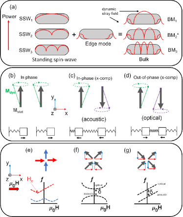
Effective inter-island coupling requires significant dynamic stray-field. Figure 1(a) illustrates different nanoisland spin-wave modes; standing spin-wave modes (SSW) which exhibit insignificant stray-field, EM predicted to exhibit mode-hybridisation due to stray-field and BM which exhibit an uncharacteristic combination of EM and SSW with stray-field emanating from both short and long edges of the nanoisland allowing opportunity for effective inter-island coupling.
When moments are aligned parallel (), no mode splitting occurs and both moments precess in-phase (Fig. 1(b)). When aligned anti-parallel (), mode-hybridisation occurs and when the energies of BM in separate nanoislands are brought close together an avoided-crossing is observed. We know from studies on synthetic antiferromagnets (syAFM) [36, 35, 44, 45] and bistable 1D nanoisland arrays [21, 23, 25] that hybridised-modes are distinguished by in-plane dynamic magnetisation moving in-phase or out-of-phase termed acoustic and optical respectively as illustrated in Figs. 1(c-d). The out-of-plane dynamic magnetisation has the opposite phase relationships, ie. acoustic moves out-of-phase and the optical moves in-phase due to opposite precession chirality. The frequency gap, , is caused by Brillouin zone folding [21, 25], typically occurring near remanance but can be shifted in field by width modification (‘staircase’) or symmetry breaking (‘brickwork’).
No strong inter-island coupling exists if external fields are applied along sublattice directions [38]. Fig. 1(e) illustrates the coercive field of the parallel-to-field nanoislands (red) are much lower than the perpendicular-to-field nanoislands (blue) and therefore the avoided-crossings cannot be observed in principle. Figures 1(f-g) show applying the field diagonally brings modes close together and each nanoisland magnetisation can be broken down into two -components. For hybridisation between neighbouring single-nanoisland modes to occur a pair of nanoislands must have configuration; in Fig. 1(g) -component (red) or Fig. 1(f) the -component (blue). It follows that avoided-crossings should be observable in a field-saturated ‘type-2’ state if measurement and preparation fields are perpendicular. Typically arrays are saturated along a given axis, then spectra measured while sweeping field along the same axis, as illustrate in Fig. 1(e) [38, 19, 46, 47], partially explaining why avoided-crossings had not been observed before. The microstate in Fig. 1(g) has modes with same field-gradient sign but should still exhibit a gap but since is typically on the order of hundreds of MHz it is likely obscured by experimental linewidth.
Mode-hybridisation in two-nanoisland arrays
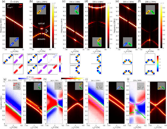
Three distinct two-nanoisland systems are shown in Fig. 2 with nanoisland-dimensions 220 by 80 by 20 nm and lattice parameter, = 300 nm. Spatial Fourier transforms applied to magnetisation time-series to generate spin-wave spectra, power and phase maps. The ‘diagonal’ two-nanoisland system (Fig. 2(a,b)) demonstrates clear distinction between the (Fig. 2a) and (b) spectra. Figure 2(a) exhibits a single mode, increasing in frequency as field is swept positive to negative along the x-axis. The corresponding power plot underneath shows equal power in both nanoislands and phase plots show both in-plane (top) and out-of-plane (bottom) magnetisation precessing in-phase. Figure 2(b) shows the case exhibiting acoustic and optical-modes with an avoided-crossing of = 126 2 MHz at zero-field, relatively small due to the centre-to-centre distance being compared with ‘chevron’ arrays with . Power maps appear similar, but phase maps reveal expected optical and acoustic-mode phase relationships. Acoustic-mode has in-plane components of magnetisation moving in-phase and optical-mode has in-plane components moving out-of-phase.
Next we examine simulated spin-wave spectra of four possible microstates (Figs. 2(c-f)) in a chevron’ geometry. In Fig. 2(c) the -component of the magnetisation () is collinear with the swept magnetic field direction and is constant for all fields. Along the -component of magnetisation () one nanoisland points up (+) and the other down (-), satisfying optical and acoustic-mode generation conditions. The two modes exhibit = 194 1 MHz, higher than Fig. 2(b) since the inter-island distance is . A large of 335 1 MHz is observed in Fig. 2(d), showing strong inter-island mode coupling.
depends not only on microstate but also the local field which is a function of magnetisation alignment favourability. Figures 2(d,e) are favourably aligned showing higher overall frequency and compared to Figs. 2(c,f) which are unfavourably configured. Since the frequency increases with effective field, , which includes a dipolar-field term , the cancellation of the dipolar-fields when two moments are both pointing into the vertex lowers the resonant frequency. In Figs. 2(c,e) the upper mode has higher or lower power respectively allowing experimental detection via asymmetry in the spin-wave signature.
Figures 2(g-j) are experimental (red/blue) and simulated (black/red/white) results for the fabricated ‘chevron’ sample with dimensions 540 by 140 by 25 nm and = 800 nm. The experimental differential FMR heatmaps are consistent with simulation. Larger is observed for microstates with favourable alignment in Figs. 2(h,i) with = 240 2 MHz and 264 12 MHz respectively. Unfavourable microstates in Figs. 2(g,j) have a smaller of 209 67 MHz and 229 2 MHz respectively demonstrating tunability via microstate. The relative optical and acoustic-mode power depends on the configuration as discussed above. The asymmetry of red and blue shading and Lorenztian fitting (green and pink dots) in Figs. 2(g,i) reveal two modes.
For conventional symmetric ASI in ‘type-2’ states mode shifting due to local field distributions is insignificant. For symmetry broken ‘type-3’ ASI states, ‘brickwork’, or width-modified ASI the vertex driven local fields can be leveraged to tune via field or microstate control.
Mode-hybridisation in ASI
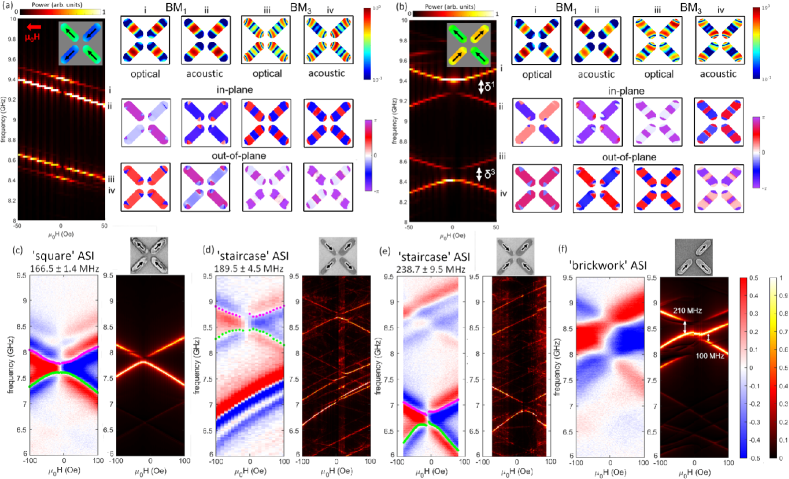
Figure 3 shows simulated spectra for square ASI microstates saturated with the measurement field parallel (a) and perpendicular (b) to the preparation field. In simulations coupling for the higher order BM is observed and we define the two gaps as = 146 2 MHz and = 127 2 MHz. are present in experiment but too faint to make quantitative assessment (see supplementary material).
Modes i and ii in Figs. 3(a,b) follow similar phase relationship as the two-island case. Remembering that the has in-plane magnetisation of coupled-nanoislands moving out-of-phase with each other. For the phase of the precession of coupled-nanoislands move in-phase. are best described by backward volume magnetostatic spin waves (BVMSW) [44] where the wavevector and magnetisation are both defined parallel to the nanoisland long-axis. and have lower frequency than the , as expected for BVMSW [48]. In Fig. 3(b) the lower power of is due to homogeneous excitation field inefficiently driving a mode where out-of-phase precession is the resonant condition.
Experimentally-measured and simulated FMR spectra for four ASI cases exhibiting collective spin-wave signatures are compared; square ASI in a perpendicular ‘type-2’ state, ‘staircase’ ASI [15] in ‘type-3’ states; wide-nanoisland and thin-nanoisland majority magnetisation and perpendicularly-saturated ‘brickwork’ ASI (Fig. 3(f)).
Figure 3(c) shows spectra for symmetric ‘square’ ASI with dimensions 460 by 150 by 25 nm and = 600 nm. = 166.5 1.4 MHz, demonstrating avoided-crossings are experimentally resolved in ASI without differential fabrication.
Figures 3(d-e) show spectra for a ‘staircase‘ ASI with dimensions 600 by 200 (wide) / 130 (thin) by 20 nm and = 800 nm. Figure 3(d), shows = 189.5 4.45 MHz, and 3(e), = 238.7 9.5 MHz. Preparing the wide-nanoisland majority ‘type-3’ state locates the avoided-crossing in the high-frequency, hybridised thin-nanoisland modes. The thin-nanoisland majority ‘type-3’ exhibits avoided-crossing in the low-frequency, wide-nanoisland hybridised modes. This demonstrates tunability of via microstate switching for RMC applications.
Figure 3(f) shows ‘brickwork’ ASI with dimensions 570 by 170 by 25 nm and = 800 nm achieved via single nanoisland removal from the unit cell. The simulated avoided-crossing gaps were = 240 25 MHz in the negative field region (right coupled nanoislands) and = 100 25 MHz in the positive field region (bottom coupled nanoislands). Unfortunately accurate experimental peaks were not extracted due to larger linewidth, however, the presence of avoided-crossings is plausible based on the similarity to the simulated spectra. Observing two different is consistent with the ‘chevron’ findings and allows tunability via field without microstate change. Lorentzian fits to experimental data are available in supplementary material.
Mode profiles
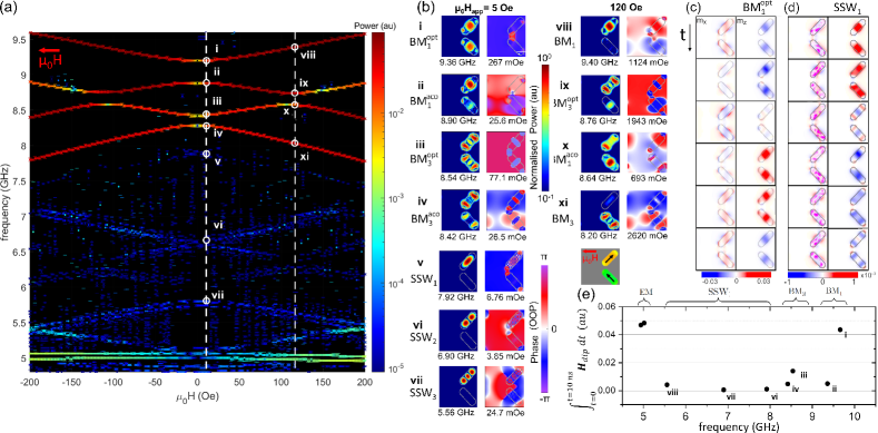
Spatial Fourier transforms are applied to the demagnetisation field to show dynamic stray-field profiles. Peak extractions are plotted in Fig. 4(a) to better highlight weak peaks. and also exhibit an avoided-crossing at 120 Oe as indicated by ix and x. At this point is optical and is acoustic. BM revert to single nanoisland-mode behaviour at high fields. Figure 4(b) shows the corresponding power and phase of each mode labeled in Fig. 4(a). have significantly lower dynamic dipole-field confined to nanoisland volume agreeing with the theoretical assumption that no coupling for is expected. Values shown underneath each phase plot in Fig. 4(b) are dipole-field calculated outside nanoislands. Modes v and vi (non-coupled SSW) show significantly smaller values than i-iv (coupled BM). and power is clearly distributed across multiple nanoislands, contrasted with SSW localised to single nanoislands.
The SSW picture applies well to low frequency modes that are not experimentally detected. Experimentally detected BM are best described by the combination of EM and SSW indicating geometry, particularly the nanoisland ends, plays a significant role. Additionally, there is a clear manifestation of stray-field emanating from long nanoisland edges.
We excite modes sinusoidally to examine time-domain dynamics. Snapshots of demagnetising fields over a full precession cycle are shown in Figs. 4(c,d) for the and SSW1 modes respectively. All modes are available in supplementary video 1. shows coherent dynamics for the in-plane components whereas mode SSW1 shows precession in only. Coherent in-plane precession for fosters inter-nanoisland coupling. The video shows the EM and SSW components of the BM have a transverse and longitudinal character respectively, seemingly arising due to the curved geometry at nanoisland ends.
Figure 4(e) shows stray-field outside magnetic volume integrated over 10 ns. has comparable stray-field to the two EM further indicating edges are vital to BM coupling. Increasing the node number for SSW allows more stray-field to escape for potential coupling to occur, however, even in the simulations SSWs are far too weak to be experimentally detected.
Tailoring coupling via geometry
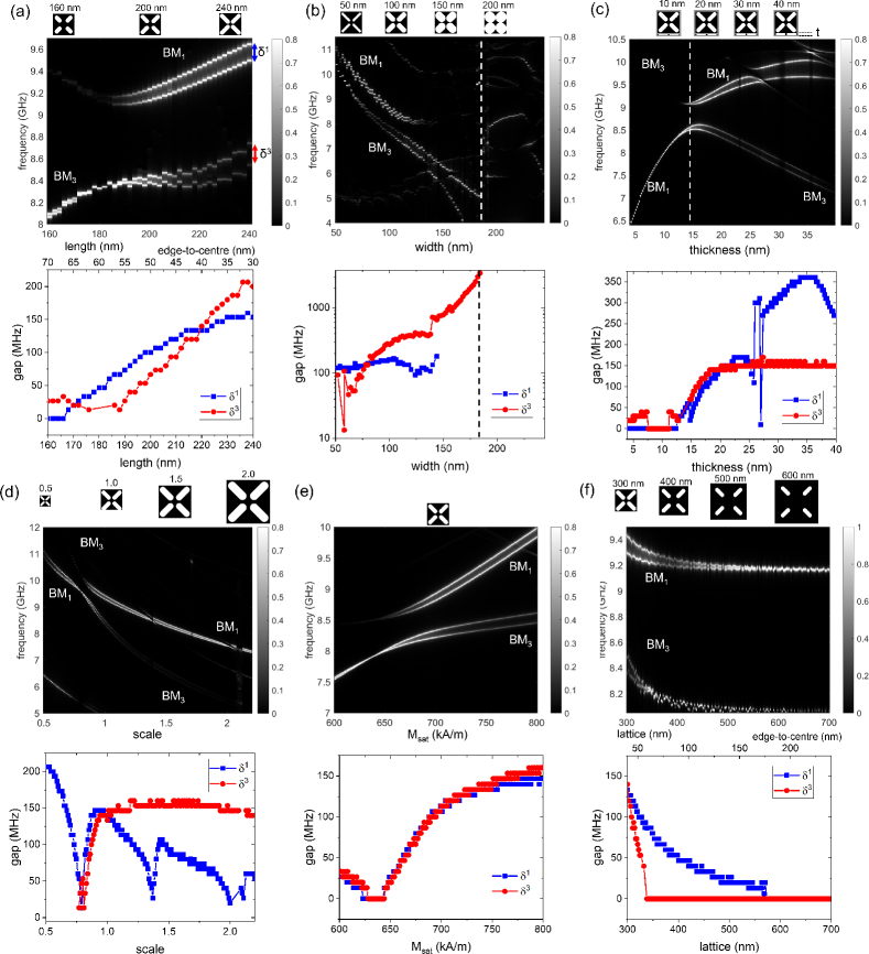
Tunability of frequency gaps between () and () modes via parameter exploration is investigated using micromagnetic-simulation. The control case is a square ASI with 220 by 80 by 20 nm = 300 nm and = 750 kA/m.
Figure 5(a) shows increasing nanoisland length 160-240 nm increases coupling strength 0-200 MHz. This is a function of nanoisland ends being in closer proximity and larger magnetic volume. Wave-vector may also play a role in determining how much stray-field escapes the nanoisland.
Figure 5(b) shows as a function of nanoisland width which remains relatively constant. disappears at 146 nm due to distortions arising from an ill-defined magnetisation vector (see supplementary). Wider nanoislands prevent the typical BM structure observed elsewhere, behaving more like a macro-spin with decreased stray-field. Interestingly depends strongly on width. The multi-nodal structure of the higher-order mode seems more robust and maintains its stray-field. The anti-node edge-proximity increases coupling significantly. The dotted line indicates the point at which neighbouring nanoislands become connected and different mode behaviour is observed.
Figure 5(c) shows how varies with thickness. A minimum thickness of 14 nm is required for measurable coupling, above which and increase up to constant value at around 20% of nanoisland width, showing additional modes at large thicknesses. Intersection with a high-order EM interrupts for 25-27 nm and continues to increase thereafter up to 35 where additional modes interfere with the . There is an avoided-crossing at 15 nm, indicated by the dotted line. Figure 4 previously demonstrated a frequency-gap occurs between and . For 14 nm and below the have higher frequency than . Each of these avoided-crossings are explained by mode hybridisation confirmed by significant stray-field (see supplementary information). Below 14 nm resemble magnetostatic surface spin-waves (MSSW) where they exhibit higher frequency than [48].
Figure 5(d) shows varying with lateral scaling achieved by in-plane cell-size increase. decreases linearly with lateral scaling as volume increases as the square and dipole-dipole strength decreases as the cube resulting in a linear decrease overall. However, is significantly decreased when intersecting with other modes at 0.8 and 1.4 and 2.0. seems much less sensitive to the scaling parameter than above 1. As can be seen in Fig. 4(b) maximal precession location of is closer to nanosisland ends. The magnetic volume increases more than the coupling distance therefore exhibiting a much more shallow drop compared to .
Figure 5(e) shows and both initially increase rapidly with with diminishing returns. These findings imply that materials with higher saturation magnetisation like CoFeB could express significantly larger spin-wave band gaps.
Finally Fig. 5(f) shows how and decrease rapidly with increasing lattice parameter. This is strong evidence that the coupling is dipole mediated as it decreases with the cube and modes become decoupled when the inter-island distance is greater than about twice the nanoisland length.
Conclusion
We investigate and explain the origin of avoided-crossings as hybridisation of single nanoisland-modes into acoustic and optical-modes which can be distinguished by precession phase relationships. Hyrbidisation between and also occurs at higher fields.
Avoided-crossings in artificial spin systems previously remained elusive due to typical experimental approaches employing preparation and measurement fields along the same axis. Rotating the applied field perpendicular to the preparation field or preparing broken-symmetry microstates (i.e. ‘type-3’) generates a clear gap, . Conversely, parallel preparation and detection field direction exhibit, , often hidden by relatively large experimental line-widths. Theoretically it was assumed that insufficient stray-field between nanoislands prevents effective coupling. We show using simulation that this holds for SSW modes (Figs.4(b) v-vii). However, experimentally detected BM are a combination of SSW and EM, exhibiting significant stray-field shown in Fig. 4(b) i-iv and avoided-crossings are confirmed via FMR. Nanoisland ends play a significant role in determining dipolar-coupling strength even between bulk-modes.
The work presented here progresses the understanding of dynamic dipole-dipole coupling in nanomagnetic arrays, both its fundamental origin and how to harness and design it into systems. Much proposed magnonic computing is based on spin-wave interference effects in continuous magnetic media, here we show discrete nano-patterned islands can strongly interfere through collective-hybridisation - allowing interference effects with the reconfigurability and flexibility benefits of 2D-RMC. The nascent magnonic computing field requires heuristics of how to optimise systems for maximum interference, coupling and nonlinearity [24]. The design rules presented here provide means for this in nano-patterned 2D ASI-based RMC. There are multiple ways of tuning in the same structure via field application or microstate selection proving ASI and related structures to be promising candidates. We hope that unveiling the ability to generate and observe these avoided-crossings will encourage future studies into dipolar magnon-magnon coupling and collective mode-hybridisation in artificial spin systems and other architectures.
Acknowledgements
TD supported by International Research Fellow of Japan Society for the Promotion of Science (Postdoctoral Fellowships for Research in Japan). WRB supported by the Leverhulme Trust (RPG-2017-257). AV supported by the EPSRC Centre for Doctoral Training in Advanced Characterisation of Materials (Grant No. EP/L015277/1). TD and JCG conceived the work. JCG, KDS and AV fabricated the samples. AV and JCG performed CAD design of the structures. JCG, AV and KDS performed FMR measurements. JCG and AV performed analysis of FMR measurements. TD performed simulations and analysis. HK and DMA supported analysis of spin-wave spectra and interpretation. TD drafted the manuscript, with contributions from all authors in editing and revision stages. Simulations were performed on the Imperial College London Research Computing Service[49]. The authors would like to thank Professor Lesley F. Cohen of Imperial College London for enlightening discussion and comments, and David Mack for excellent laboratory management. The authors declare no competing interests. Code and data-sets generated during and/or analysed during the current study are available from the corresponding author on reasonable request.
References
- Wang et al. [2006] R. F. Wang, C. Nisoli, R. S. Freitas, J. Li, W. McConville, B. J. Cooley, M. S. Lund, N. Samarth, C. Leighton, V. H. Crespi, et al., Nature 439, 303 (2006).
- Nisoli et al. [2013] C. Nisoli, R. Moessner, and P. Schiffer, RMP 85, 1473 (2013).
- Skjærvø et al. [2020] S. H. Skjærvø, C. H. Marrows, R. L. Stamps, and L. J. Heyderman, Nat. Rev. Phys. 2, 13 (2020).
- Gartside et al. [2018] J. C. Gartside, D. M. Arroo, D. M. Burn, V. L. Bemmer, A. Moskalenko, L. F. Cohen, and W. R. Branford, Nat. Nanotechnol. 13, 53 (2018).
- Kaffash et al. [2021] M. T. Kaffash, S. Lendinez, and M. B. Jungfleisch, Phys. Lett. A 402, 127364 (2021).
- Barman et al. [2020] A. Barman, S. Mondal, S. Sahoo, and A. De, J. Appl. Phys. 128, 170901 (2020).
- Lendinez and Jungfleisch [2019] S. Lendinez and M. Jungfleisch, J. Condens. Matter Phys. 32, 013001 (2019).
- Gliga et al. [2020] S. Gliga, E. Iacocca, and O. G. Heinonen, APL Materials 8, 040911 (2020).
- Talapatra et al. [2020] A. Talapatra, N. Singh, and A. O. Adeyeye, Phys. Rev. Appl. 13, 1 (2020).
- Gartside et al. [2020] J.-C. Gartside, S. G. Jung, S. Y. Yoo, D. M. Arroo, A. Vanstone, T. Dion, K. D. Stenning, and W. R. Branford, Communications Physics 3, 1 (2020).
- Grollier et al. [2020] J. Grollier, D. Querlioz, K. Camsari, K. Everschor-Sitte, S. Fukami, and M. Stiles, Nat. Electron. , 1 (2020).
- Hon et al. [2021] K. Hon, Y. Kuwabiraki, M. Goto, R. Nakatani, Y. Suzuki, and H. Nomura, Appl. Phys. Express 14, 033001 (2021).
- Nomura et al. [2021] H. Nomura, H. Kubota, and Y. Suzuki, in Reservoir Computing (Springer, 2021) pp. 361–374.
- Jensen and Tufte [2020] J. H. Jensen and G. Tufte, in Artificial Life Conference Proceedings (MIT Press, 2020) pp. 376–383.
- Gartside et al. [2021a] J. C. Gartside, K. D. Stenning, A. Vanstone, T. Dion, H. H. Holder, D. M. Arroo, H. Kurebayashi, and W. R. Branford, arXiv preprint arXiv:2107.08941 arXiv:2107.08941 (2021a).
- Dion et al. [2019] T. Dion, D. Arroo, K. Yamanoi, T. Kimura, J. Gartside, L. Cohen, H. Kurebayashi, and W. Branford, PRB 100, 054433 (2019).
- Gartside et al. [2021b] J. C. Gartside, A. Vanstone, T. Dion, K. D. Stenning, D. M. Arroo, H. Kurebayashi, and W. R. Branford, Nat. Commun. 12 (2021b).
- Vanstone et al. [2021] A. Vanstone, J. C. Gartside, K. D. Stenning, T. Dion, D. M. Arroo, and W. R. Branford, arxiv (2021), arXiv:2106.04406 .
- Lendinez et al. [2021] S. Lendinez, M. T. Kaffash, and M. B. Jungfleisch, Nano Lett. 21, 1921 (2021).
- Grundler [2015] D. Grundler, Nature Physics 11, 438 (2015).
- Topp et al. [2010] J. Topp, D. Heitmann, M. P. Kostylev, and D. Grundler, PRL 104, 207205 (2010).
- Krawczyk and Grundler [2014] M. Krawczyk and D. Grundler, J. Phys. Condens. Matter 26, 123202 (2014).
- Haldar et al. [2016] A. Haldar, D. Kumar, and A. O. Adeyeye, Nat. Nanotechnol. 11, 437 (2016).
- Chumak et al. [2021] A. Chumak, P. Kabos, M. Wu, C. Abert, C. Adelmann, A. Adeyeye, J. Åkerman, F. Aliev, A. Anane, A. Awad, et al., IEEE Transactions on Quantum Engineering (2021).
- Topp et al. [2011] J. Topp, G. Duerr, K. Thurner, and D. Grundler, Pure Appl. Chem. 83, 1989 (2011).
- Wang et al. [2009] Z. K. Wang, V. L. Zhang, H. S. Lim, S. C. Ng, M. H. Kuok, S. Jain, and A. O. Adeyeye, Appl. Phys. Lett. 94, 83112 (2009).
- Al-Wahsh et al. [2011] H. Al-Wahsh, A. Akjouj, B. Djafari-Rouhani, and L. Dobrzynski, Surf. Sci. Rep. 66, 29 (2011).
- Ma et al. [2012] F. S. Ma, H. S. Lim, V. L. Zhang, S. C. Ng, and M. H. Kuok, Nanoscale Res. Lett. 7, 498 (2012).
- Gubbiotti et al. [2005] G. Gubbiotti, S. Tacchi, G. Carlotti, P. Vavassori, N. Singh, S. Goolaup, A. O. Adeyeye, A. Stashkevich, and M. Kostylev, Phys. Rev. B Condens. Matter 72, 224413 (2005).
- Gubbiotti et al. [2007] G. Gubbiotti, S. Tacchi, G. Carlotti, N. Singh, S. Goolaup, and M. Adeyeye, A. O.and Kostylev, Appl. Phys. Lett. 90, 092503 (2007).
- Arroo et al. [2019] D. M. Arroo, J. C. Gartside, and W. R. Branford, PRB 100, 214425 (2019).
- Kruglyak et al. [2010] V. Kruglyak, S. Demokritov, and D. Grundler, J. Phys. D 43, 264001 (2010).
- Lenk et al. [2011] B. Lenk, H. Ulrichs, F. Garbs, and M. Münzenberg, Phys. Rep. 507, 107 (2011).
- Chumak et al. [2015] A. V. Chumak, V. I. Vasyuchka, A. A. Serga, and B. Hillebrands, Nat. Phys 11, 453 (2015).
- Shiota et al. [2020] Y. Shiota, T. Taniguchi, M. Ishibashi, T. Moriyama, and T. Ono, PRL 125, 017203 (2020).
- Sud et al. [2020] A. Sud, C. Zollitsch, A. Kamimaki, T. Dion, S. Khan, S. Iihama, S. Mizukami, and H. Kurebayashi, PRB 102, 100403 (2020).
- Gliga et al. [2013] S. Gliga, A. Kákay, R. Hertel, and O. G. Heinonen, Phys. Rev. Lett. 110, 117205 (2013).
- Li et al. [2017] Y. Li, G. Gubbiotti, F. Casoli, S. A. Morley, F. J. Gonçalves, M. C. Rosamond, E. H. Linfield, C. H. Marrows, S. McVitie, and R. L. Stamps, J. Appl. Phys. 121, 103903 (2017).
- Heyderman and Stamps [2013] L. J. Heyderman and R. L. Stamps, J. Phys. Condens. Matter 25, 363201 (2013).
- Kostylev et al. [2007] M. P. Kostylev, G. Gubbiotti, J. G. Hu, G. Carlotti, T. Ono, and R. L. Stamps, PRB - Condens. Matt. and Mater. Phys. 76, 054422 (2007).
- Urbanek et al. [2010] M. Urbanek, V. Uhlr, P. Babor, E. Kolibalova, T. Hrnir, and T. Spousta, J. and. Sikola, Nanotechnology 21, 10.1088/0957-4484/21/14/145304 (2010).
- Iacocca et al. [2020] E. Iacocca, S. Gliga, and O. G. Heinonen, Phys. Rev. Appl. 13, 44047 (2020).
- Vansteenkiste et al. [2014] A. Vansteenkiste, J. Leliaert, M. Dvornik, M. Helsen, F. Garcia-Sanchez, and B. Van Waeyenberge, AIP Adv. 4, 107133 (2014).
- Kalinikos and Slavin [1986] B. Kalinikos and A. Slavin, J. phys., C, Solid state phys. 19, 7013 (1986).
- Liensberger et al. [2019] L. Liensberger, A. Kamra, H. Maier-Flaig, S. Geprägs, A. Erb, S. T. Goennenwein, R. Gross, W. Belzig, H. Huebl, and M. Weiler, PRL 123, 117204 (2019).
- Li et al. [2016] Y. Li, G. Gubbiotti, F. Casoli, F. J. Gonçalves, S. A. Morley, M. C. Rosamond, E. H. Linfield, C. H. Marrows, S. McVitie, and R. L. Stamps, J. Phys. D: Appl. Phys. 50, 015003 (2016).
- Jungfleisch et al. [2016] M. Jungfleisch, W. Zhang, E. Iacocca, J. Sklenar, J. Ding, W. Jiang, S. Zhang, J. Pearson, V. Novosad, J. B. Ketterson, et al., PRB 93, 100401 (2016).
- Chumak et al. [2008] A. V. Chumak, A. A. Serga, B. Hillebrands, and M. P. Kostylev, Appl. Phys. Lett. 93, 22508 (2008).
- [49] Imperial college research computing service.