Extending the kinetic and thermodynamic limits of molecular-beam epitaxy utilizing suboxide sources or metal-oxide catalyzed epitaxy
Abstract
We observe a catalytic mechanism during the growth of III-O and IV-O materials by suboxide molecular-beam epitaxy (-MBE). By supplying the molecular catalysts In2O and SnO we increase the growth rates of Ga2O3 and In2O3. This catalytic action is explained by a metastable adlayer , which increases the reaction probability of the reactants Ga2O and In2O with active atomic oxygen, leading to an increase of the growth rates of Ga2O3 and In2O3. We derive a model for the growth of binary III-O and IV-O materials by -MBE and apply these findings to a generalized catalytic description for metal-oxide catalyzed epitaxy (MOCATAXY), applicable to elemental and molecular catalysts. We derive a mathematical description of -MBE and MOCATAXY providing a computational framework to set growth parameters in previously inaccessible kinetic and thermodynamic growth regimes when using the aforementioned catalysis. Our results indicate MOCATAXY takes place with a suboxide catalyst rather than with an elemental catalyst. As a result of the growth regimes achieved, we demonstrate a Ga2O3/Al2O3 heterostructure with an unrivaled crystalline quality, paving the way to the preparation of oxide device structures with unprecedented perfection.
I I. Introduction
Molecular-beam epitaxy (MBE) takes place under non-equilibrium conditions and surface kinetics plays a dominant role in the MBE growth process—allowing growth modes to be intentionally manipulated Arthur (1968); Copel et al. (1989); Neugebauer et al. (2003); Lewis et al. (2017); Vogt et al. (2017). For decades, the single-step reaction mechanism occurring during the MBE growth of III-V (e.g., GaAs, GaN, AlN) Ploog (1982); Calleja et al. (1999); Fernández-Garrido et al. (2008) and II-VI (e.g., ZnSe, ZnO) Zhu et al. (1989); Kato et al. (2003) compound semiconductors has defined MBE as a rather simple and straightforward thin film technique, especially when compared with chemical vapor deposition methods Hirako et al. (2005). In contrast to the growth of III-V and II-VI materials, the surface kinetics of III-O (e.g., Ga2O3 and In2O3) Tsai et al. (2010); Vogt and Bierwagen (2015, 2016a, 2016b, 2016c); Vogt (2017); Vogt et al. (2018) and IV-O (e.g., SnO2) White et al. (2008) compounds is governed by a complex reaction pathway, resulting in a two-step reaction mechanism to form the intended compound. The formation and subsequent desorption of ad-molecules, called suboxides (e.g., Ga2O, In2O, SnO), define the growth-limiting step for these classes of materials. The result is a rather narrow growth window within the adsorption-controlled regime White et al. (2008); Vogt and Bierwagen (2016a, b); Oshima et al. (2018); Vogt et al. (2018).
By engineering the MBE processes, two variants of MBE have recently been developed. These variants extend the kinetic and thermodynamic limits within which III-O and IV-O materials may be grown. The first variant, suboxide MBE (-MBE) Vogt et al. (2021), refers to a technique that uses the decomposition of III-VI and IV-VI compounds (i.e., MexOy) by group III and IV elements Vogt and Bierwagen (2015); Vogt (2017) as well as a special MBE source chemistry Vogt et al. (2021) to produce suboxide molecular beams that consist almost entirely (typically ¿ 99.9%) of a single suboxide molecular species (i.e., MexOy-x). Stoichiometric coefficients of MexOy and MexOy-x are and for III-O (e.g., Ga2O3, In2O3) and and for IV-O (e.g., SnO2) materials.
Using the -MBE approach, the growth-limiting step occurring during the growth of III-O and IV-O materials by conventional MBE is bypassed, enabling the growth of films with excellent structural quality and surface smoothness at growth rates exceeding and comparatively low growth temperature () Vogt et al. (2021). The second variant is metal-oxide catalyzed epitaxy (MOCATAXY), a method involving the introduction of a catalyst into oxide growth systems Vogt (2017); Vogt et al. (2017); Kracht et al. (2017); Vogt et al. (2018). Using this technique, the growth-limiting step of III-O compounds is bypassed by the catalyst Vogt et al. (2017). It has been proposed that MOCATAXY results from metal-exchange catalysis (MEXCAT) Vogt et al. (2017) and has been observed on various growth surfaces for the formation of Ga2O3 and (AlxGa1-x)2O3 Vogt et al. (2017); Kracht et al. (2017); Vogt et al. (2018); Mazzolini et al. (2019); Mauze et al. (2020a, b) as well as during other physical vapor deposition methods Kneiß et al. (2019). Nevertheless, the underlying physics leading to the observed catalysis has been explained differently—experimentally Vogt et al. (2017); Kracht et al. (2017) and theoretically Wang et al. (2020)—and thus remains disputable.

.
In this Letter, the combination of -MBE and MOCATAXY is investigated and shown to result in a marked extension of the kinetic and thermodynamic limits of the growth of Ga2O3 and In2O3. By supplying suboxide molecular beams of Ga2O, In2O, and SnO, a growth rate (Γ) enhancement of Ga2O3 and In2O3 is observed. Quantitative models describing this enhanced growth rate during -MBE as well as during the catalyzed -MBE of III-O thin films are derived and applied to the experimental observations to extract model parameters. Through a systematic comparison of experimental Γ data from different growth systems and growth methods (i.e., MOCATAXY during -MBE and conventional MBE), a generalization of the proposed MEXCAT mechanism Vogt et al. (2017) is developed. This generalized growth mechanism is applicable to the growth of Ga2O3 and In2O3 by conventional MBE and -MBE.
II II. Suboxide MBE (-MBE) model
We begin by deriving a growth-rate model for the growth of III-VI and IV-VI compounds with general formula MexOy by -MBE and validate it by using Ga2O3 and In2O3 as examples. Figure 1 shows the growth kinetics of Ga2O3 and In2O3 as a function of their respective growth parameters. In panels (a)–(d), the film growth rate, Γ, is observed to increase linearly with the incident flux of suboxide, (i.e., or ), in the O-rich regime. This linear increase in Γ reaches a plateau in the adsorption-controlled regime when exceeds the flux of active atomic oxygen, . The growth kinetics for the growth of III-O compounds by -MBE are thus the same as those of III-V and II-VI materials when grown by conventional MBE Vogt et al. (2021).
Figures 1(e) and 1(f) depict Γ as a function of and , respectively. For the same growth conditions, Γ of Ga2O3 on Ga2O3(010) [hollow squares] is larger than that of Ga2O3 on Ga2O3(01) [solid squares]; see panel (e). This result is similar to the growth of Ga2O3 by conventional MBE on Ga2O3(01) versus on Ga2O3(010) substrates S. et al. (2012); Oshima et al. (2018); Mazzolini et al. (2020). Comparing the growth kinetics of Ga2O3(01) and In2O3(111) [e.g., the data in panel (a) with the data in panel (d)] establishes that the range of within which high-quality films of In2O3 can be grown at high Γ is larger than that for Ga2O3. This result is also similar to the growth of Ga2O3 and In2O3 by conventional MBE Vogt and Bierwagen (2015, 2016b); Vogt et al. (2018).
To model the growth of binary oxides (MexOy) from their suboxides (MexOy-x), we take the single-step reaction kinetics of -MBE Vogt et al. (2021) into account. Here, the growth takes place via the reaction
with constant describing the MexOy formation rate. Adsorbate and solid phases are denoted as and , respectively. Based on reaction (II), we set up a generalized growth-rate model describing the growth of these materials by -MBE:
| (1) | ||||
| (2) | ||||
| (3) |
The surface densities of adsorbed cationic reactants (), O adsorbates, and formed products () are denoted as , , and , respectively. Their time derivative is described by the operator . The surface lifetimes of and O are given by and , respectively. The -, orientation-, and growth-system-dependent sticking probability of O can be derived by considering two competing processes: the chemisorption of O and the desorption of O from the given adsorption sites, described by the reaction rates and , respectively,
| (4) |
with , frequency factor , and the respective energy barrier . Following the Kisliuk model Kisliuk (1957), the O sticking probability Lombardo and Bell (1991); Lipponer et al. (2012) is given by
| (5) |
with dimensionless pre-factor and activation barrier . In the case of a high O desorption barrier or a high O adsorption barrier, the limits of Eq. (5) are (i) and (ii) , respectively, satisfying our conditions of . Figure 2 depicts the model results of Eq. (5) of our model for Ga2O3 and In2O3 using the parameters given in Table 1.
| ) | ) | |||
|---|---|---|---|---|
| -Ga2O3(01) | ||||
| -Ga2O3(010) | ||||
| In2O3(111) |
Solving Eqs. (1) and (2) with respect to and and inserting their solutions into Eq. (3) yields an analytical expression for Γ described by three kinetic parameters: , , and , see Eqs. (26)–(32). To reduce the complexity of the model we assume that O adsorbate desorption is negligible and use and . Assuming that the observed reaction processes follow a thermally activated Arrhenius behavior, we further reduce the complexity of our model by forming the product
| (10) |
with pre-exponential factor and activation energy . The latter expression yields a larger or a longer the higher the growth rate Γ of the intended compound. This is in agreement with experiment as shown in Fig. 1.

We apply the solution of this model to the binary growth rate data of Ga2O3 and In2O3 by -MBE depicted in Fig. 1 and extract the kinetic parameters summarized in Table 1. To extract the parameters we use an iterative approach. For example, for the growth of Ga2O3 by -MBE we first establish that the functional form of the equations accurately describe the growth of (01) oriented -Ga2O3 films, as plotted in Figs. 1(a) and 1(b). Having established that the functional form of the equations [solutions given by Eqs. (26)–(32)] accurately describe the growth of (01) oriented -Ga2O3 films, the model is next expanded to an additional orientation, (010) -Ga2O3 films using the data in Fig. 1(c).
II.1 Orientation-dependent growth rate of -Ga2O3
As a quantitative result, we find that the range of that can be used to produce high-quality epitaxial films at high Γ (i.e., a growth window) of (01)-oriented Ga2O3 films is narrower than for the growth of (010)-oriented Ga2O3 films, which, in turn, is narrower than the one for the growth of (111)-oriented In2O3 films. This is because of the different reaction efficiencies, , of Ga2O and In2O with active O species (more detailed explanation below in the text). In addition, we explain the different sticking probabilities , e.g., as obtained for Ga2O3() and Ga2O3(010), by the activity of surface reactions between Ga2O and O adsorbates being dependent on the orientation of the surface on which the reaction takes place. In other words, the reservoir of active atomic oxygen for Ga2O oxidation on Ga2O3(010) is larger than the one on Ga2O3(01). This finding can be transferred to the growth of Ga2O3 by conventional MBE where a similar dependence of Ga2O3 growth rate is observed. We propose that this Γ dependence results from an orientation-dependent activity of the oxidation of Ga2O to Ga2O3 Vogt and Bierwagen (2016a); Oshima et al. (2018) and that the underlying reason is due to the orientation-dependent vertical and lateral bond strengths between ad-atoms and the substrate surfaces S. et al. (2012); Mazzolini et al. (2020). In Refs. S. et al. (2012); Oshima et al. (2018); Mazzolini et al. (2020) the orientation dependence of the growth rate on the () plane, , is given for -Ga2O3: . We observe this same order of growth rate as a function of surface orientation for the growth of Ga2O3 by -MBE, and conclude that the orientation-dependent values of the sticking probability can be related to the orientation-dependent reaction activities of adorbates, underlying the observed order of for -Ga2O3, see Fig. 2.
III III. MOCATAXY combined with -MBE
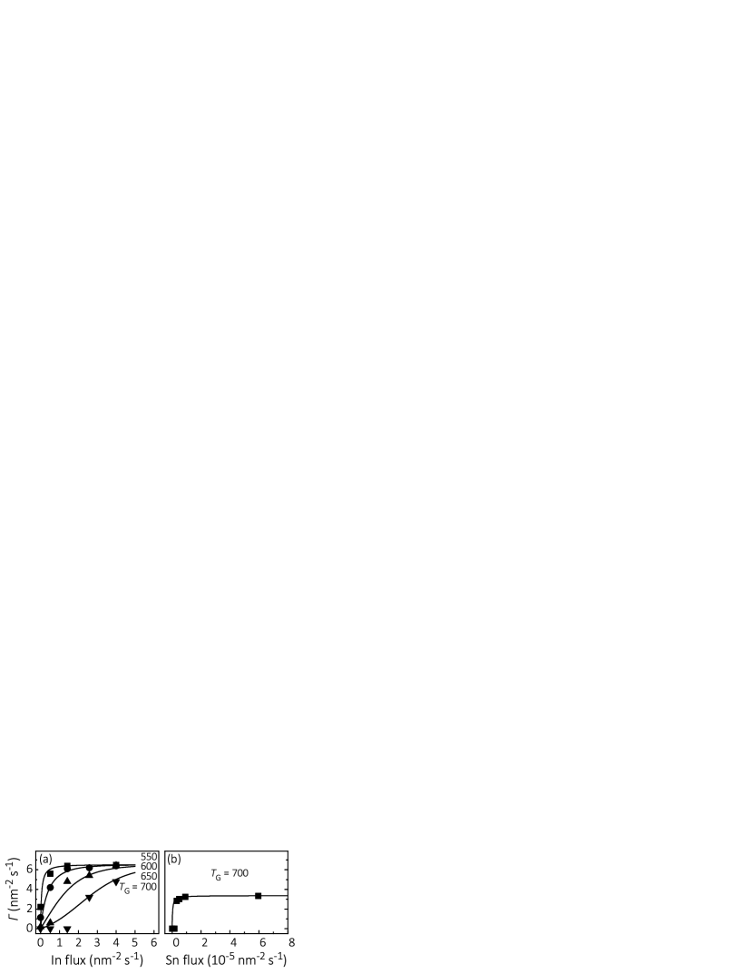
We next describe the enhancement to the growth rate of Ga2O3 and In2O3 due to the presence of the catalysts In2O and SnO, i.e., the combined effects of -MBE and MOCATAXY. As depicted in Figs. 3(a)–3(c), we observe a drastic enhancement in Γ of heteroepitaxial -Ga2O3(01) grown on Al2O3(0001) and homoepitaxial -Ga2O3(010) grown on -Ga2O3(010) using the suboxides In2O and SnO as catalysts. The catalytic effect of SnO on the growth rate of Ga2O3 is stronger than that of In2O. It is also stronger for the growth of -Ga2O3(01) (solid symbols) than for the growth of -Ga2O3(010) (hollow symbols). The stronger catalytic effect of SnO compared with In2O can be explained by their different vapor pressures, i.e., Colin et al. (1965); Valderrama-N and Jacob (1977); Adkison et al. (2020). Thus, under similar growth conditions, the surface lifetime of SnO is longer than that of In2O. Hence, SnO can be re-oxidized more often than In2O Vogt (2017); Vogt et al. (2017), and the O reservoir that ultimately ends up oxidizing Ga2O in the presence of SnO is larger than that for Ga2O oxidation in the presence of In2O. Figures 3(d)–3(f) depict Γ of Ga2O3 as a function of and , respectively. When SnO is used as a catalyst it is evident from the data that the catalytic effect on Ga2O3(01) is stronger than it is on Ga2O3(010). As shown below in Eq. (19), the catalytic activity, , decreases with increasing O flux. Therefore, the weaker catalytic effect observed on -Ga2O3(010) compared with the effect on -Ga2O3(01) may be explained by the higher surface-dependent sticking probability (values are given in Table 1). Further studies on the atomic incorporation and surface segregation of residual Sn and In in the grown thin films, when using SnO and In2O as catalysts, respectively, need to be performed. Nevertheless, energy-dispersive x-ray spectroscopy (EDXS), secondary-ion mass spectrometry (SIMS), and atomic probe tomography (APT) have already shown that the concentrations of In Vogt et al. (2017, 2018); Mauze et al. (2020a) and Sn Kracht et al. (2017) in Ga2O3 as well as in (AlxGa1-x)2O3 films are below . This is consistent with our x-ray diffraction (XRD) results showing only diffraction peaks from Ga2O3 in the thin films, an example of which is shown in Fig. 4.

Comparing Figs. 3(f) and 3(g) reveals that the growth rates Γ of -Ga2O3(01) and -Ga2O3(010) using solely SnO and as catalysts are very similar (under otherwise identical growth conditions). We thus conclude that SnO suppresses In2O as a catalyst, i.e., the catalytic effects are not additive: the presence of SnO inhibits (or isolates) the catalytic activity of In2O in the SnO–In2O–Ga2O–O system. We predict the same effect for MOCATAXY by conventional MBE, i.e., when using the elemental catalysts In Vogt et al. (2017) and Sn Kracht et al. (2017) in combination for the growth of Ga2O3 in the Sn–In–Ga-O system.
Figure 3(h) shows the catalytic effect of SnO on Γ of In2O3(111) grown on Al2O3(0001) substrates. The solid circle in Fig. 3(h) corresponds to the growth rate of In2O3 determined by x-ray reflectivity (XRR) in the absence of SnO. In the presence of SnO, the growth rate of In2O3 (again measured by XRR) is seen to increase by a factor of , i.e., far larger than the effect caused by additional SnO incorporation into In2O3. SIMS eag (2020) and x-ray fluorescence (XRF) eag (2020) were used to quantify the Sn content present in the In2O3 films grown with the SnO catalyst. A value of Sn in In2O3 was observed by SIMS and XRF independent of the SnO fluxes in the range.
This result indicates that SnO increases the available O reservoir for the oxidation of In2O to In2O3 by a factor of (at these growth conditions). This finding is in line with the data plotted in Figs. 3(f) and 3(g), i.e., that SnO has a higher reactivity with O than In2O. We explain the catalytic action of SnO on In2O by their different vapor pressures Colin et al. (1965); Valderrama-N and Jacob (1977); Adkison et al. (2020). Thus, SnO provides a larger O reservoir for In2O oxidation than is available in the absence of SnO. The In2O-SnO-O system is the first catalytic system observed for MBE growth beyond Ga2O3-based systems Vogt et al. (2017); Kracht et al. (2017); Vogt et al. (2018); Mazzolini et al. (2019); Mauze et al. (2020a, b). The discovery of MOCATAXY during -MBE and its extension to In2O3 suggests its universality for the MBE growth of a multitude of oxide compounds (during -MBE as well as conventional MBE).
We explain the observed catalysis during the growth of Ga2O3 and In2O3 by -MBE by the formation of a metastable adlayer between the catalyst and O, e.g., or . As experimentally and mathematically shown by Fig. 1, Table 1, and Eqs. (1)–(5), In2O possesses a higher surface reactivity with active O than does Ga2O, leading to a higher growth rate of In2O3 compared with Ga2O3 at comparable growth conditions. This behavior is similar to the growth of Ga2O3 and In2O3 by conventional MBE Vogt and Bierwagen (2015, 2016c), which was explained by the different oxidation efficiencies of the elements Sn, In, and Ga following the order: Vogt and Bierwagen (2015); Vogt (2017); Vogt et al. (2017). Taking the ratio of maximum available O for Ga2O and In2O oxidation (data plotted in Figs. 1(b) and 1(d) and flux conversions given in Eqs. (36) from mixtures of O2 and 10% O3 Theis and Schlom (Electrochemical Society, Pennington, 1997) at a background pressure of , we obtain . This result is very similar to Vogt and Bierwagen (2015); Vogt (2017); Vogt et al. (2017) observed during conventional MBE growth. We surmise following Ref. Vogt (2017) that the same value of observed during MOCATAXY in conventional MBE and -MBE arises from what is the second reaction step of conventional MBE and the sole reaction step of -MBE, where the suboxide reacts with O to complete the formation of the intended oxide (e.g., ) Vogt et al. (2018) and not to the suboxide formation step (e.g., ) Vogt et al. (2018). Thus, for the discussion and analysis that follow we use during -MBE. These oxidation efficiencies follow the same order in as was observed for growth by conventional MBE Vogt (2017); Vogt et al. (2017).
III.1 A. Generalized metal-exchange catalytic model
We propose that the role of the catalyst (e.g., In2O, SnO, In Vogt et al. (2017), or Sn Kracht et al. (2017)) is to increase the O adsorbate reservoir of the reactant (e.g., Ga2O or Ga) by forming through the reaction
| (11) |
with examples of being In2O–O, In–O, SnO–O, or Sn–O. In the presence of , is unstable and catalyzes the incorporation of into the intended product (e.g, Ga2O3), while decreasing the reaction barrier of with O. Thus, reaction (11) is subsequently followed by the reaction
| (12) |
Equation (12) describes the consumption of while forming the product ) and releasing on the growth surface. The catalyst may be re-oxidized Vogt et al. (2017), leading to an increase in the available O reservoir for the reactant (), and thus to an extension of the kinetic and thermodynamic limits to the formation of .
An adlayer formed by In has also been observed during the formation of GaN using In as a surface active agent (surfactant) Neugebauer et al. (2003). Here, the In adlayer enables an enhanced diffusion channel for the Ga and N adsorbates. Moreover, a surface instability of In–O bonds in the presence of Fe Wagner et al. (2016) and Ga Vogt et al. (2017) has been observed during conventional MBE. We emphasize, however, the catalytic effect we are describing must not be confused with effects resulting from surfactants during the growth of III-V compounds by conventional MBE Copel et al. (1989); Neugebauer et al. (2003); Lewis et al. (2017).
In order to describe MOCATAXY for elemental (e.g., In Vogt et al. (2017) and Sn Kracht et al. (2017)) and molecular catalysts (e.g., In2O and SnO) as well as for different materials (e.g., Ga2O3 and In2O3) mathematically, we would have to take into account the surface populations of , , and atomic O together with the surface density of the that forms following the Langmuir-Hinshelwood mechanism Wintterlin et al. (1997). We may reduce the complexity of the model significantly by only taking into account the most likely reactions involved in the formation of , following the Eley-Rideal formalism Eley and Rideal (1940). The resulting set of coupled differential equations reads:
| (13) | ||||
| (14) | ||||
| (15) |
with the adatom density and desorption rate constant of the catalyst , as well as the surface coverage of . The second and third terms in Eq. (13) refer to the formation rates of and , respectively, and the factor assures that constitutes a surface phase. The last term in Eq. (13) accounts for the desorption of from the growth surface, and (with the dimension of ) represents the cross section of colliding with O Vogt et al. (2017). The impinging fluxes of and are denoted as and , respectively. We note that the structure of the model introduced here is similar to the MEXCAT model given in Ref. Vogt et al. (2017). The improvement of the model given in this work and its generalization to elemental and molecular catalysts arises by taking a cationic-like, metastable adlayer into account. This allows MOCATAXY to be described for the growth of ternary systems involving molecular catalysts [e. g., In2O (Fig. 3) and SnO (Fig. 3)] as well as elemental catalysts [e. g., In (Fig. 5) and Sn (Fig. 5)].
III.2 B. Suboxide catalysts
Our results thus indicate that MOCATAXY takes place with a suboxide catalyst (e.g., for being In2O–O or SnO–O) and not with an elemental catalyst (e.g., for being In–O or Sn–O). For conventional MBE, i.e., when using elemental source materials, we assume the reaction of the metal to form the suboxide (e.g., ) occurs very rapidly Vogt and Bierwagen (2018), and thus, the catalysis takes place between the suboxide reactant and , satisfying reactions (11) and (12). Should the reaction of not occur very rapidly, we would see Ga desorption (at least a fraction of it), and a plateau in Γ in the adsorption-controlled regime during the growth of Ga2O3 by conventional MBE; similar to the Γ plateau, e.g., observed during the growth of GaN by conventional MBE Fernández-Garrido et al. (2008). The subsequent desorption of the rapidly formed Ga2O is the growth-rate-limiting step in conventional MBE as it removes active O from the growth front (by forming Ga2O), leading to the decrease in Γ in the adsorption-controlled regime as well as at elevated Tsai et al. (2010); Vogt (2017); Vogt and Bierwagen (2018). In -MBE, the formation of Ga2O (through ) is bypassed since Ga2O is directly provided from the source. Therefore, the O-consuming step is now avoided and a plateau in Γ of Ga2O3 in the adsorption-controlled regime occurs Vogt et al. (2021). The assumption that MOCATAXY takes place with a suboxide catalyst is further supported by our finding in this work that the oxidation efficiency for In2O and Ga2O during MOCATAXY by -MBE follows the same order in as for Ga and In during conventional MBE, i.e., for -MBE [this work] versus for conventional MBE Vogt (2017); Vogt et al. (2017). Nevertheless, we emphasize that the microscopic origin and reaction pathways of MOCATAXY during -MBE and conventional MBE requires further investigation to fully understand which species are indeed involved leading to the observed catalysis given in this work and presented in Refs. Vogt (2017); Vogt et al. (2017); Kracht et al. (2017); Vogt et al. (2018); Mazzolini et al. (2019); Mauze et al. (2020a, b); Kneiß et al. (2019); Wang et al. (2020).
Solving Eqs. (13) and (14) with respect to and yields , consistent with our observation of negligible incorporation () of into the grown thin films for the data plotted in Fig. 3. Inserting the solution for into Eq. (15) yields the following expression, valid for first-order kinetics with ,
| (16) |
The free parameters are the pseudo-flux
| (17) |
with (assumed for all species as a first approximation Lombardo and Bell (1991)) and energy . The value of depends linearly on (e.g., and ),
| (18) |
with denoting the evaporation enthalpy, e.g, of In2O and SnO, and describing its increase with increasing . The other free parameter is the catalytic activity coefficient, . For (ranging from 1 to 0), we use a linear approximation depending on impinging , i.e.,
| (19) |
with describing the decrease of with . By an iterative approach of our model to the experimental growth rate data, the values obtained of , , and for In2O and SnO are given in Table 2.
| ) | ) | ||
|---|---|---|---|
| -Ga2O3(01):In2O | Valderrama-N and Jacob (1977) | ||
| -Ga2O3(010):In2O | Valderrama-N and Jacob (1977) | ||
| -Ga2O3(01):SnO | Colin et al. (1965) | ||
| -Ga2O3(010):SnO | Colin et al. (1965) | ||
| In2O3(111):SnO |
The evaporation enthalpies of In2O and SnO on Ga2O3 surfaces correspond to the values given in the literature, as noted in Table 2. Only the value of for SnO on the In2O3(111) surface is slightly above the literature value, indicating an additional energy term caused by vertical and lateral interactions between adsorbed species and the In2O3(111) surface. The increase in with , described by the parameter , indicates an increase in lateral adsorbate binding energy with increasing . An analogous behavior has also been observed for the desorption kinetics of In on Ga2O3 Vogt et al. (2017) and Ga on GaN He et al. (2006). We explain the linear decrease of with by a linear increase of O adsorbates with , i.e., . It has been shown that an increase in promotes the incorporation of In during the growth of (InxGa1-x)2O3 by conventional MBE; this decreases the catalytic strength of In for the formation of Ga2O3 Vogt and Bierwagen (2016c); Vogt (2017); Vogt et al. (2017); Mazzolini et al. (2020). We therefore explain the decrease in with increasing by a decreasing diffusion length of and , and thus, a decrease in the probability of reaction (12) to occur.
III.3 C. Elemental catalysts
We have applied the above model to the data published in Refs. Vogt et al. (2017) and Kracht et al. (2017) for MOCATAXY during conventional MBE growth of Ga2O3, i.e., using elemental In and Sn as catalysts (see Appendix). For the former, our model and the parameters given in this Letter can describe the data published in Ref. Vogt et al. (2017) with the same accuracy. For the latter, we provide the first mathematical description of a catalytic system involving the element Sn (see Appendix). These results, and the comparison among different MBE variants (i.e., -MBE and conventional MBE), confirm the accuracy of our refined and generalized MEXCAT model, describing MOCATAXY for elemental and molecular catalysts.
III.4 D. Obtained ‘pseudo’ Ga2O3/Al2O3 heterostructure
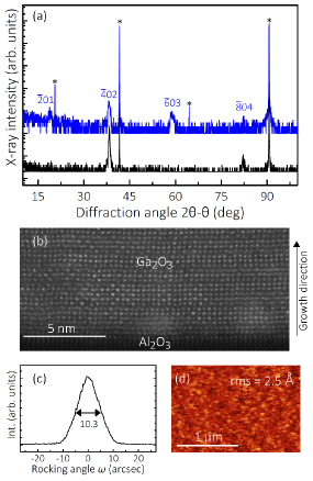
As a result of combining -MBE with MOCATAXY, in Figs. 4(a)–4(d), we demonstrate an unprecedented ‘pseudo’ -Ga2O3(01)/Al2O3(0001) heterostructure with unparalleled crystalline perfection. Figure 4(a) shows - x-ray diffraction (XRD) scans of a thick SnO-catalyzed Ga2O3 film (black trace) and a thick non-catalyzed Ga2O3 film grown by -MBE under similar growth conditions (, , and ). The SnO-catalyzed Ga2O3 film is the same film that is plotted in Fig. 3(f) as a solid-black star. It was grown at , , and . The reflections of the non-catalyzed Ga2O3 thin film coincide with the -Ga2O3(01) phase grown with its (01) plane parallel to the (0001) plane of the Al2O3 substrate. In contrast, the XRD scan of the SnO-catalyzed Ga2O3 film shows only the even reflections of the -Ga2O3 phase grown with its (01) plane parallel to the (0001) plane of the Al2O3 substrate. We speculate that the ‘pseudo’ -Ga2O3(01)/Al2O3(0001) contains an aperiodic occurrence of low-energy stacking faults, parallel to the (01) plane of the Ga2O3 film that reduce the number of the observed XRD diffraction peaks of the ‘pseudo’ -Ga2O3(01) phase. This hypothesis is consistent with calculations showing that the stacking fault energy in -Ga2O3 is low Fu et al. (2019); McCluskey (2020), experimental observation of high densities of stacking faults in -Ga2O3 films Schewski et al. (2016), and the scanning transmission electron microscopy (STEM) image depicted in Fig. 4(b). The epilayer shows a single-crystalline structure with an abrupt interface to the Al2O3(0001) substrate at the bottom of the image. Figure 4(c) shows a transverse scan (rocking curve) across the symmetric reflection of the same ‘pseudo’ -Ga2O3(01) film. The measured full width at half maximum (FWHM) is just ; this is a measure of the out-of-plane mosaic spread of the thin film. Figure 4(d) depicts an atomic force microscope (AFM) image of the surface morphology of the same SnO-catalyzed Ga2O3 film; it has a root mean square roughness (rms) of . The obtained rocking curve of and smooth surface morphology of provide the best results obtained for any Ga2O3 thin film grown on Al2O3(0001) by any method. We point out that optimizations utilizing the unprecedented growth regimes—becoming accessible by the combination of -MBE with MOCATAXY—still need to be performed to further improve the crystalline perfection of the grown Ga2O3-based heterostructures.
We note that in the absence of a catalyst, Ga2O3 does not form at this high of . In addition, at a lower catalyst flux of SnO [depicted as the open star in Fig. 3 (f)] compared with the sample grown at a higher SnO flux [depicted as the solid star in Fig. 3 (f) and Fig. 4] we have not measured the ‘pseudo’ -Ga2O3(01) phase, but instead see the ‘conventional’ -Ga2O3(01) peaks by XRD (data not shown in this work). We therefore conclude that extending the kinetic (e.g., higher possible ) and thermodynamic limits (e.g., different surface chemical potential) by combining -MBE with MOCATAXY benefits the formation of the ‘pseudo’ -Ga2O3(01)/Al2O3(0001) heterostructure that has unparalleled crystalline perfection.
IV IV. Conclusion
As we have demonstrated, the nature of the model derived to describe MOCATAXY using elemental and molecular catalysts does depend on the specific growth surface. We note, however, that the growth surface may change the kinetic parameters used in our model as shown for the examples of -Ga2O3(01) and -Ga2O3(010) using In2O or SnO as catalysts in this work.
Finally, the increase in the growth rates of Ga2O3 and In2O3 by -MBE that occur when using the catalysts SnO and In2O, demonstrates MOCATAXY as a potentially inherent feature in conventional MBE growth Vogt et al. (2017); Kracht et al. (2017); Vogt et al. (2018); Mazzolini et al. (2019); Mauze et al. (2020a, b) as well as in -MBE growth. Furthermore, our results provide deeper insight into this catalysis, indicating MOCATAXY occurs through a suboxide catalyst rather than with an elemental catalyst. This more broad applicability of MOCATAXY opens an unprecedented path for the epitaxial synthesis of thin films by intentionally extending the kinetic and thermodynamic limits during their growth processes. If successful, this could enable the growth of (yet) unknown crystal phases and unprecedented functional electronic materials.
V V. Appendix
We apply the generalized MOCATAXY model, Eqs. (13)–(19), to published catalytic data using elemental In Vogt et al. (2017) and elemental Sn Kracht et al. (2017) as catalysts for the growth of Ga2O3 by MBE. The parameters used in Eqs. (18) for In and Sn are collected in Table 3. Within experimental uncertainty, the obtained corresponds to the vaporization enthalpies of elemental In Alcock et al. (1984) and Sn Colin et al. (1965) as given in the literature; the values are given in Table 3. Moreover, for our model we use (the catalytic activity), the same value of as used in Ref. Vogt et al. (2017).
Figures 5(a) and 5(b) show our results for the growth of Ga2O3 by MBE when supplying In and Sn as elemental catalysts, respectively. Our model drawn in Fig. 5(a) (solid lines) describes the data published in Ref. Vogt et al. (2017) with the same accuracy as the previously established metal-exchange catalysis (MEXCAT) model Vogt et al. (2017). Figure 5(b) plots the catalyzed growth rate data of Ga2O3 taken from Ref. Kracht et al. (2017). Our model applied to this data is drawn as the solid line. It precisely describes the Sn-catalyzed growth of Ga2O3 by MBE and is the first quantitative description of MOCATAXY using Sn as a catalyst. To model the Sn-catalyzed data, we linearly extrapolated the value of given in Eq. (41) while using the O flux conditions published in Ref. Kracht et al. (2017).
To conclude, our model introduced in the main text is able to the describe the growth of Ga2O3 and In2O3 by -MBE as well as conventional MBE when using elemental and molecular catalysts. This is achieved by introducing a cationic-like, catalytic adlayer .
V.1 A. Detailed model of the growth of III-VI materials by -MBE
The analytical solution of the growth rate, Γ, of Eqs. (1)–(3) for III-VI compound materials is:
| Γ | (26) | |||
with
| (27) | ||||
| (28) | ||||
| (29) | ||||
| (30) | ||||
| (31) |
and
| (32) | ||||
The growth rates of Ga2O3 and In2O3 as presented in Fig. 1 are explicitly modeled with Eqs. (26)–(32).
V.2 B. Detailed model of the growth IV-VI materials by -MBE
The analytical solution for Γ of Eqs. (1)–(3) for IV-VI compound materials is:
| Γ | (33) |
with
| (34) |
We predict that Γ of IV-VI materials (e.g., SnO2)—obtained by -MBE—may be modeled by Eqs. (33) and (34) with the same accuracy as Γ modeled for III-VI materials (e.g., Ga2O3 and In2O3) by Eqs. (26)–(32); this is demonstrated in the main text.
V.3 C. Conversion factors for and
The model uses reactant fluxes, (e.g., Ga2O, In2O, SnO, Ga, In, Sn), and active atomic oxygen fluxes, (from active O3 or O species), in . The conversion factors for -MBE used in an ozone MBE system are:
| (35) | ||||
| (36) | ||||
The reactant fluxes, , are measured prior to growth by a quartz crystal microbalance (QCM) in , with the density of the QCM set to . These QCM readings are readily converted to absolute fluxes using the known masses of the Ga2O, In2O, and SnO molecules that condense onto the QCM. The active atomic oxygen fluxes given result from an oxidant, , with mixtures of O2 and 10% O3 in the oxygen molecular-beam Theis and Schlom (Electrochemical Society, Pennington, 1997). The different oxidation efficiencies were taken from Ref. Vogt (2017) while using the results obtained for -MBE.
| ) | ||
|---|---|---|
| Ga2O3:In | Alcock et al. (1984) | |
| Ga2O3:Sn | Colin et al. (1965) |
The conversion factors for conventional MBE used in an oxygen plasma-assisted MBE system are:
| (40) | ||||
| (41) | ||||
The beam-equivalent pressure (BEP), , of the reactant fluxes is measured prior to growth by an ion gauge in . is converted from a pressure into a flux using the kinetic theory of gases Schlom and Harris Jr. (Noyes Publications, New Jersey, USA, 1995). The oxygen flux, , was measured in standard cubic centimeters per minute (SCCM), and a radio-frequency plasma power of was applied. The conversion factors were taken from Ref. Vogt (2017) and applied to the data given in Ref. Kracht et al. (2017). We note the conversion factors Vogt (2017) and data Kracht et al. (2017) were obtained in different MBE systems. Thus, the actual conversion may differ slightly due to the different geometries of the MBE systems used. Nevertheless, using the same conversion factors for different MBE systems is a practical and reasonable approach.
VI IV. ACKNOWLEDGMENTS
K.A., J.P.M., D.J., H.G.X., D.A.M., and D.G.S. acknowledge support from the AFOSR/AFRL ACCESS Center of Excellence under Award No. FA9550-18-1-0529. J.P.M. also acknowledges support from the National Science Foundation within a Graduate Research Fellowship under Grant No. DGE-1650441. P.V. and J.P. acknowledges support from ASCENT, one of six centers in JUMP, a Semiconductor Research Corporation (SRC) program sponsored by DARPA. F.V.E.H. acknowledges support from the Alexander von Humboldt Foundation in the form of a Feodor Lynen fellowship. F.V.E.H. also acknowledges support from the National Science Foundation (NSF) [Platform for the Accelerated Realization, Analysis and Discovery of Interface Materials (PARADIM)] under Cooperative Agreement No. DMR-2039380. J.P.M. acknowledges the support of a National Science Foundation Graduate Research Fellowship under Grant No. DGE-1650441. This work made use of the Cornell Center for Materials Research (CCMR) Shared Facilities, which are supported through the NSF MRSEC Program (Grant No. DMR-1719875). Substrate preparation was performed, in part, at the Cornell NanoScale Facility, a member of the National Nanotechnology Coordinated Infrastructure (NNCI), which is supported by the NSF (Grant No. NNCI-2025233).
References
- Arthur (1968) J. R. Arthur, “Interaction of Ga and As2 Molecular Beams with GaAs Surfaces,” J. Appl. Phys. 39, 4032 (1968).
- Copel et al. (1989) M. Copel, M. C. Reuter, E. Kaxiras, and R. M. Tromp, “Surfactants in epitaxial growth,” Phys. Rev. Lett. 63, 632 (1989).
- Neugebauer et al. (2003) J. Neugebauer, T. K. Zywietz, M. Scheffler, J. E. Northrup, H. Chen, and R. M. Feenstra, “Adatom Kinetics On and Below the Surface: The Existence of a New Diffusion Channel,” Phys. Rev. Lett. 90, 056101 (2003).
- Lewis et al. (2017) R. B. Lewis, P. Corfdir, H. Li, J. Herranz, C. Pfüller, O. Brandt, and L. Geelhaar, “Quantum Dot Self-Assembly Driven by a Surfactant-Induced Morphological Instability,” Phys. Rev. Lett. 119, 086101 (2017).
- Vogt et al. (2017) P. Vogt, O. Brandt, H. Riechert, J. Lähnemann, and O. Bierwagen, “Metal-Exchange Catalysis in the Growth of Sesquioxides: Towards Heterostructures of Transparent Oxide Semiconductors,” Phys. Rev. Lett. 119, 196001 (2017).
- Ploog (1982) K. Ploog, “Molecular Beam Epitaxy of III-V Compounds: Application of MBE-Grown Films,” Ann. Rev. Mater. Sci. 12, 123 (1982).
- Calleja et al. (1999) E. Calleja, M. A. Sánchez-García, F. J. Sánchez, F. Calle, F. B. Naranjo, E. Muñoz, S. I. Molina, A. M. Sánchez, F. J. Pacheco, and R. García, “Growth of III-nitrides on Si(1 1 1) by molecular beam epitaxy Doping, optical, and electrical properties,” J. Crys. Growth 201, 296 (1999).
- Fernández-Garrido et al. (2008) S. Fernández-Garrido, G. Koblmüller, E. Calleja, and J. S. Speck, “In situ GaN decomposition analysis by quadrupole mass spectrometry and reflection high-energy electron diffraction,” J. Appl. Phys. 104, 1 (2008).
- Zhu et al. (1989) Ziqiang Zhu, Minoru Hagino, Katsuhiro Uesugi, Satomi Kamiyama, Masami Fujimoto, and Takafumi Yao, “Surface Processes in ALE and MBE Growth of ZnSe: Correlation of RHEED Intensity Variation with Surface Coverage,” Jpn. J. Appl. Phys. 28, 1659 (1989).
- Kato et al. (2003) K. Kato, M. Sano, K. Miyamoto, and T. Yao, “Effect of O/Zn Flux Ratio on Crystalline Quality of ZnO Films Grown by Plasma-Assisted Molecular Beam Epitaxy,” Jpn. J. Appl. Phys. 42, 2241 (2003).
- Hirako et al. (2005) Akira Hirako, Kazuhide Kusakabe, and Kazuhiro Ohkawa, “Modeling of Reaction Pathways of GaN Growth by Metalorganic Vapor-Phase Epitaxy Using TMGa/NH3/H2 System: A Computational Fluid Dynamics Simulation Study,” Jpn. J. Appl. Phys. 44, 874 (2005).
- Tsai et al. (2010) M.-Y. Tsai, O. Bierwagen, M. E. White, and J. S. Speck, “-Ga2O3 growth by plasma-assisted molecular beam epitaxy,” J. Vac. Sci. Technol. A 28, 354 (2010).
- Vogt and Bierwagen (2015) P. Vogt and O. Bierwagen, “The competing oxide and sub-oxide formation in metal-oxide molecular beam epitaxy,” Appl. Phys. Lett. 106, 081910 (2015).
- Vogt and Bierwagen (2016a) P. Vogt and O. Bierwagen, “Reaction kinetics and growth window for plasma-assisted molecular beam epitaxy of Ga2O2: Incorporation of Ga vs. Ga2O desorption,” Appl. Phys. Lett. 108, 072101 (2016a).
- Vogt and Bierwagen (2016b) P. Vogt and O. Bierwagen, “Comparison of the growth kinetics of In2O3 and Ga2O3 and their suboxide desorption during plasma-assisted molecular beam epitaxy,” Appl. Phys. Lett. 109, 062103 (2016b).
- Vogt and Bierwagen (2016c) P. Vogt and O. Bierwagen, “Kinetics versus thermodynamics of the metal incorporation in molecular beam epitaxy of (InxGa1-x)2O3,” APL Mater. 4, 086112 (2016c).
- Vogt (2017) P. Vogt, Growth Kinetics, Thermodynamics, and Phase Formation of group-III and IV oxides during Molecular Beam Epitaxy, Ph.D. thesis, Humboldt University of Berlin (2017).
- Vogt et al. (2018) P. Vogt, A. Mauze, F. Wu, B. Bonef, and J. S. Speck, “Metal-oxide catalyzed epitaxy (MOCATAXY): the example of the O plasma-assisted molecular beam epitaxy of -(AlxGa1-x)2O3/-Ga2O3 heterostructures,” Appl. Phys. Express 11, 115503 (2018).
- White et al. (2008) M. E. White, M.-Y. Tsai, F. Wu, and J. S. Speck, “Plasma-assisted molecular beam epitaxy and characterization of SnO2(101) on -plane sapphire,” J. Vac. Sci. Technol., A 26, 1300 (2008).
- Oshima et al. (2018) Y. Oshima, E. Ahmadi, S. Kaun, F. Wu, and J. S. Speck, “Sn doping of (010) -Ga2O3 films grown by plasma-assisted molecular beam epitaxy,” Semicon. Sci.Technol. 33, 015013 (2018).
- Vogt et al. (2021) Patrick Vogt, Felix V E Hensling, Kathy Azizie, Celesta S Chang, David Turner, Jisung Park, Jonathan P McCandless, Hanjong Paik, Brandon J Bocklund, Georg Hoffman, Oliver Bierwagen, Depdeep Jena, Huili G Xing, Shin Mou, David A Muller, Shun-Li Shang, Zi-Kui Liu, and Darrell G Schlom, “Adsorption-controlled growth of Ga2O3 by suboxide molecular-beam epitaxy,” APL Mater. 9, 031101 (2021).
- Kracht et al. (2017) M. Kracht, A. Karg, J. Schörmann, M. Weinhold, D. Zink, F. Michel, M. Rohnke, M. Schowalter, B. Gerken, A. Rosenauer, P. J. Klar, J. Janek, and M. Eickhoff, “Tin-Assisted Synthesis of -Ga2O3 by Molecular Beam Epitaxy,” Phys. Rev. Applied 8, 054002 (2017).
- Mazzolini et al. (2019) P. Mazzolini, P. Vogt, R. Schewski, C. Wouters, M. Albrecht, and O. Bierwagen, “Faceting and metal-exchange catalysis in (010) -Ga2O3 thin films homoepitaxially grown by plasma-assisted molecular beam epitaxy,” APL Mater. 7, 022511 (2019).
- Mauze et al. (2020a) Akhil Mauze, Yuewei Zhang, Takeki Itoh, Feng Wu, and James S. Speck, “Metal oxide catalyzed epitaxy (MOCATAXY) of -Ga2O3 films in various orientations grown by plasma-assisted molecular beam epitaxy,” APL Mater. 8, 021104 (2020a).
- Mauze et al. (2020b) A. Mauze, Y. Zhang, T. Itoh, E. Ahmadi, and J. S. Speck, “Sn doping of (010) -Ga2O3 films grown by plasma-assisted molecular beam epitaxy,” Appl. Phys. Lett. 117, 222102 (2020b).
- Kneiß et al. (2019) M. Kneiß, A. Hassa, D. Splith, C. Sturm, H. Von Wenckstern, T. Schultz, N. Koch, M. Lorenz, and M. Grundmann, “Tin-assisted heteroepitaxial PLD-growth of -Ga2O3 thin films with high crystalline quality,” APL Mater. 7, 022516 (2019).
- Wang et al. (2020) Mengen Wang, Sai Mu, and Chris G. Van De Walle, “Role of Ga and In adatoms in the epitaxial growth of -Ga2O3,” Phys. Rev. B 102, 035303 (2020).
- S. et al. (2012) Kohei S., A. Kuramata, T. Masui, E. G. Víllora, K. Shimamura, and S. Yamakoshi, “Device-Quality -Ga2O3 Epitaxial Films Fabricated by Ozone Molecular Beam Epitaxy,” Appl. Phys. Express 5, 035502 (2012).
- Mazzolini et al. (2020) P. Mazzolini, A. Falkenstein, C. Wouters, R. Schewski, T. Markurt, Z. Galazka, M. Martin, M. Albrecht, and O. Bierwagen, “Substrate-orientation dependence of -Ga2O3 (100), (010), (001), and (01 ) homoepitaxy by indium-mediated metal-exchange catalyzed molecular beam epitaxy (MEXCAT-MBE),” APL Mater. 8, 011107 (2020).
- Kisliuk (1957) P. Kisliuk, “The sticking probabilities of gases chemisorbed on the surfaces of solids,” J. Phys. Chem. Solids 3, 95 (1957).
- Lombardo and Bell (1991) Stephen J. Lombardo and Alexis T. Bell, “A review of theoretical models of adsorption, diffusion, desorption, and reaction of gases on metal surfaces,” Surf. Sci. Rep 13, 1 (1991).
- Lipponer et al. (2012) M. A. Lipponer, N. Armbrust, M. Dürr, and U. Höfer, “Adsorption dynamics of ethylene on Si(001),” J. Chem. Phys. 136, 144703 (2012).
- Vogt and Bierwagen (2018) P. Vogt and O. Bierwagen, “Quantitative subcompound-mediated reaction model for the molecular beam epitaxy of III-VI and IV-VI thin films: Applied to Ga2O3, In2O3, and SnO2,” Phys. Rev. Mater. 2, 120401(R) (2018).
- Colin et al. (1965) R. Colin, J. Drowart, and G. Verhaegen, “Mass-spectrometric study of the vaporization of tin oxides. Dissociation energy of SnO,” Trans. Faraday Soc. 61, 1364 (1965).
- Valderrama-N and Jacob (1977) J. Valderrama-N and K.T. Jacob, “Vapor pressure and dissociation energy of (In2O),” Thermochim. Acta 21, 215 (1977).
- Adkison et al. (2020) K. M. Adkison, S.-L. Shang, B. J. Bocklund, D. Klimm, D. G. Schlom, and Z.-K. Liu, “Suitability of binary oxides for molecular-beam epitaxy source materials: A comprehensive thermodynamic analysis,” APL Mater. 8, 081110 (2020).
- eag (2020) EAG Laboratories (Syracuse, New York, USA, 2020).
- Theis and Schlom (Electrochemical Society, Pennington, 1997) C. D. Theis and D. G. Schlom, (High Temperature Materials Chemistry IX, edited by K.E. Spear, Vol. 97–39, Electrochemical Society, Pennington, 1997) pp. 610–616.
- Wagner et al. (2016) M. Wagner, P. Lackner, S. Seiler, S. Gerhold, J. Osiecki, K. Schulte, L. A. Boatner, M. Schmid, B. Meyer, and U. Diebold, “Well-Ordered In Adatoms at the In2O3(111) Surface Created by Fe Deposition,” Phys. Rev. Lett. 117, 206101 (2016).
- Wintterlin et al. (1997) J. Wintterlin, S. Völkening, T. V.W. Janssens, T. Zambelli, and G. Ertl, “Atomic and Macroscopic Reaction Rates of a Surface-Catalyzed Reaction,” Science 278, 1931 (1997).
- Eley and Rideal (1940) D. D. Eley and E. K. Rideal, “Parahydrogen Conversion on Tungsten,” Nature 146, 401 (1940).
- He et al. (2006) L. He, Y. T. Moon, J. Xie, M. Muñoz, D. Johnstone, and H. Morkoç, “Gallium desorption kinetics on (0001) GaN surface during the growth of GaN by molecular-beam epitaxy,” Appl. Phys. Lett. 88, 071901 (2006).
- Fu et al. (2019) B. Fu, Z. Jia, W. Mu, Y. Yin, J. Zhang, and X. Tao, “A review of -Ga2O3 single crystal defects, their effects on device performance and their formation mechanism,” J. Semicond. 40, 011804 (2019).
- McCluskey (2020) M. D. McCluskey, “Point defects in Ga2O3,” J. Appl. Phys. 127, 101101 (2020).
- Schewski et al. (2016) R. Schewski, M. Baldini, K. Irmscher, A. Fiedler, T. Markurt, B. Neuschutz, T. Remmele, T. Schulz, G. Wagner, Z. Galazka, and M. Albrecht, “Evolution of planar defects during homoepitaxial growth of -Ga2O3 layers on (100) substrates—A quantitative model,” J. Appl. Phys. 120, 225308 (2016).
- Alcock et al. (1984) C. B. Alcock, V. P. Itkin, and M. K. Horrigan, “Vapour Pressure Equations for the Metallic Elements: 298–2500 K,” Can. Metall. Q. 309, 23 (1984).
- Schlom and Harris Jr. (Noyes Publications, New Jersey, USA, 1995) D. G. Schlom and J. S. Harris Jr., (Molecular Beam Epitaxy, Chapter 6, Page 544, edited by R. F. C. Farrow, Noyes Publications, New Jersey, USA, 1995).