[ style=chinese, auid=001, bioid=1, orcid=0000-0001-8274-0616 ] \creditConceptualization, Methodology, Writing Original draft, Writing-Reviewing and Editing
[ style=chinese, auid=002, bioid=2, orcid=0000-0001-5017-2095 ] \creditConceptualization, Funding acquisition
[ style=chinese, auid=003, bioid=3, orcid=0000-0002-7507-4579 ] \creditMethodology, Writing-Reviewing and Editing
[ style=chinese, auid=004, bioid=4, orcid=0000-0002-7159-5107 ] \creditSupervision,Conceptualization, Writing-Reviewing and Editing
[ style=chinese, auid=005, bioid=5, orcid=0000-0003-0717-5009 ] \creditMethodology, Supervision, Conceptualization, Writing-Reviewing and Editing, Funding acquisition \cormark[1]
[ style=chinese, auid=006, bioid=6, orcid=0000-0002-0253-5733 ] \creditConceptualization, Funding acquisition
[1]
[1]Corresponding author
Design and Implementation of Real-Time Localization System (RTLS) based on UWB and TDoA Algorithm
Abstract
[S U M M A R Y] Nowadays, accurate localization plays an essential role in many fields, like target tracking and path planning. The challenges of indoor localization include inadequate localization accuracy, unreasonable anchor deployment in complex scenarios, lack of stability, and the high cost. So the universal positioning technologies cannot meet the real application requirements scarcely. To overcome these shortcomings, a comprehensive Ultra Wide-Band (UWB) based RTLS is presented in this paper. We first introduce the architecture of real-time localization system, then propose a new wireless clock synchronization (WCS) scheme, finally discuss the time difference of arrival (TDoA) algorithm. We define the time-base selection strategy for TDoA algorithm, and analyze the relationship between anchor deployment and positioning accuracy. The Extended Kalman Filter (EKF) method is presented for non-linear dynamic localization estimation, and it performs well in terms of stability and accuracy in moving target.
keywords:
Indoor localization \sepUltra wide-band (UWB) \sepTime difference of arrival (TDoA) \sepWireless clock synchronization (WCS) \sepTime-base selection strategy \sepExtended kalman filter (EKF)A better performance UWB based real-time localization system is designed.
A new wireless clock synchronization scheme covering both a single master anchor and multiple master anchors is proposed.
The typical anchor deployment schemes are presented, and the time-base selection strategy for TDoA algorithm are defined.
1 Inroduction
accuracy position information of person or device is vital for military, security, and commercial applications. For example, knowing the location information of living creature in danger situation can help firefighters with an emergency rescue, and indoor location technology can also facilitate consumers’ shopping in the supermarket. Indoor Real-Time Localization System (RTLS) has not yet been widely deployed, although many neoteric technologies, such as computer vision and wireless communications solutions, are adopted (Alarifi et al., 2016; Alwan and Hussain, 2017). It is not easy to integrate many other technologies into a unified solution. With the increase of indoor positioning demand, how to obtain accurate location information becomes particularly important (Pughat and Sharma, 2017).
There are a few kinds of wireless sensor technologies used in indoor positioning, such as WiFi, RFID (Papapostolou and Chaouchi, 2011) and BLE. Whereas, high frequency positioning with WiFi needs a high power consumption, so a low-power consumption but with a high localization accuracy solution is needed (Curran and Furey, 2008). UWB (Ultra Wide-Band) is a radio technology that uses pulse rather than the carrier to transmit data, ensuring its low-power consumption. The Federal Communications Commission (FCC) has identified that UWB pulses should occupy a broad frequency bandwidth () or a relative bandwidth () with a restricted frequency band from 3.1 GHz to 10.6 GHz and -41.3 dBm/MHz power density (Commission, 2002). (Li et al., 2011) proposes a low-complexity and noncoherent detector to detect UWB signals in the wireless sensor networks (WSNs). According to the manufacturer’s datasheets, indoor point to point measurement using UWB has high accuracy, achieving the accuracy within 10cm. Besides, the frequency band of UWB makes the UWB devices data transmission rate up to 500Mbit/s (Decawave, 2017b), (Decawave, 2017a). An OpenSource hardware-platform based on the DW1000 UWB chip called Wi-PoS is proposed in (Herbruggen et al., 2019). The PolyPoint project presents a multi-antenna plan to eliminate the influence of polarization mismatch between anchors in (Kempke et al., 2015). (Kim et al., 2010) proposes and analyzes the UWB-WBAN system, which could be applied to design for WBAN applications. (You and Lee, 2011) proposes an improved pilot-based algorithm based on CFO and SFO in UWB-OFDM systems with cyclic delay diversity. (Barbieri et al., 2021) studies the employment of UWB in a factory and a Bayesian filtering solution is developed to track the targets. (Bottigliero et al., 2021) introduces a new low-cost RTLS without time synchronization among sensors and uses a one-way communication solution to reduce the consumption of tags. (Pelka and Hellbrück, 2016) presents a unified architecture for location systems to integrate hardware, software and algorithms. (Pease et al., 2017) proposes a semantic IIoT architecture using a communication economical RSSI/ToF ranging method.
This paper presents an UWB-based RTLS, including system architecture, wireless clock synchronization scheme, anchor deployment scheme, and time-base selection strategy. The findings made in this paper offer a solid foundation for all available UWB based indoor localization systems design and deployment. The main contributions of this paper can be summarized as follows:
-
[1.]
-
1.
We design a better performance UWB based real-time localization system. According to the characteristics of UWB and TDoA positioning scheme, the system architecture of RTLS is summarized.
-
2.
We propose a new wireless clock synchronization scheme covering both a single master anchor and multiple master anchors.
-
3.
We present the typical deployment schemes of a single master anchor and multiple master anchors based on the principle of anchor deployment, define the time-base selection strategy for TDoA algorithm in signal master anchor and multiple master anchors systems, and reveal the relationship between anchor deployment and positioning accuracy.
The rest of the paper is organized as follows. In Section 2, a literature review is given. In Section 3, a detailed description of RTLS is given, including the architecture of real-time localization system, and the UWB-based Wireless Positioning Network (U-WPN). In Section 4, we introduce the Wireless Clock Synchronization (WCS) scheme. The localization algorithm based on TDoA and EKF will be discussed in Section 5. The reference scheme of anchor deployment and time-base selection strategy will be given in Section 6. Experiments and performance analysis are discussed in Section 7, and finally, conclusions and future work are given in Section 8.
2 Related Works
UWB technology has drawn enough attention to outdoor/indoor localization in recent years. Several methods are used for localization in wireless networks (Al-Ammar et al., 2014), and these approaches can generally be divided into four categories: (RSSI), (ToF), (ToA), and (TDoA). The positioning method based on TDoA has attracted more attention.
The Atlas (Tiemann et al., 2016) realizes a UWB-based project with DWM1000 b8. (Djaja-Josko and Kolakowski, 2016b) focuses on TDoA based WCS techniques, which relies on pairs of packets and a recorded timestamp, is implemented in RTLS. (Zandian and Witkowski, 2018) proposes an effective synchronization method of the unilateral TDoA applied in ultra-wideband (UWB) localization systems. (Chen et al., 2019) describes an architecture of multi-level IoT positioning system to reduce the deployment cost. (Vashistha and Law, 2020) presents an E-DTDOA based ranging algorithm used for clock drift estimation, which achieves high time resolution. (Sidorenko et al., 2020) investigates multiple clock-drift correction methods for ToA and TDoA, in particular the DW1000 transceiver. A hybrid positioning algorithm that combines ToA and received signal strength (RSSI) measurements are presented in (Khan et al., 2013). (Comuniello et al., 2020) proposes a best linear unbiased estimator (BLUE) algorithm based on ultrasound TDoA measurements and investigates the geometrical dilution of precision (GDOP). An algorithm framework that integrates EKF, UKF, and PF is developed in (Ullah et al., 2020). (Djaja-Josko and Kolakowski, 2016a) describes an UWB based localization system using the TDoA technology. (Xu et al., 2021) proposes an error-ellipse-resampling particle flter method for cooperative target tracking. A sensor network and a hybrid algorithm for tracking based on both RSS and TDoA is presented in (b7014849).
The positioning solutions mentioned above are algorithm oriented and do not fully consider the relationships between hardware, software, localization scheme, and anchor deployment. The RTLS proposed in this paper focuses on the shortcomings of existing solutions. The outcomes such as the architecture of real-time localization system, the framework of central localization engine, the wireless clock synchronization scheme, and the deployment scheme, could be used as a foundation for all the available UWB based indoor localization solutions.
3 System Design
This section describes the details of our new UWB real-time localization system (RTLS), including the architecture of real-time localization system, and the UWB-based Wireless Positioning Network (U-WPN).
3.1 Architecture of Real-time Localization System
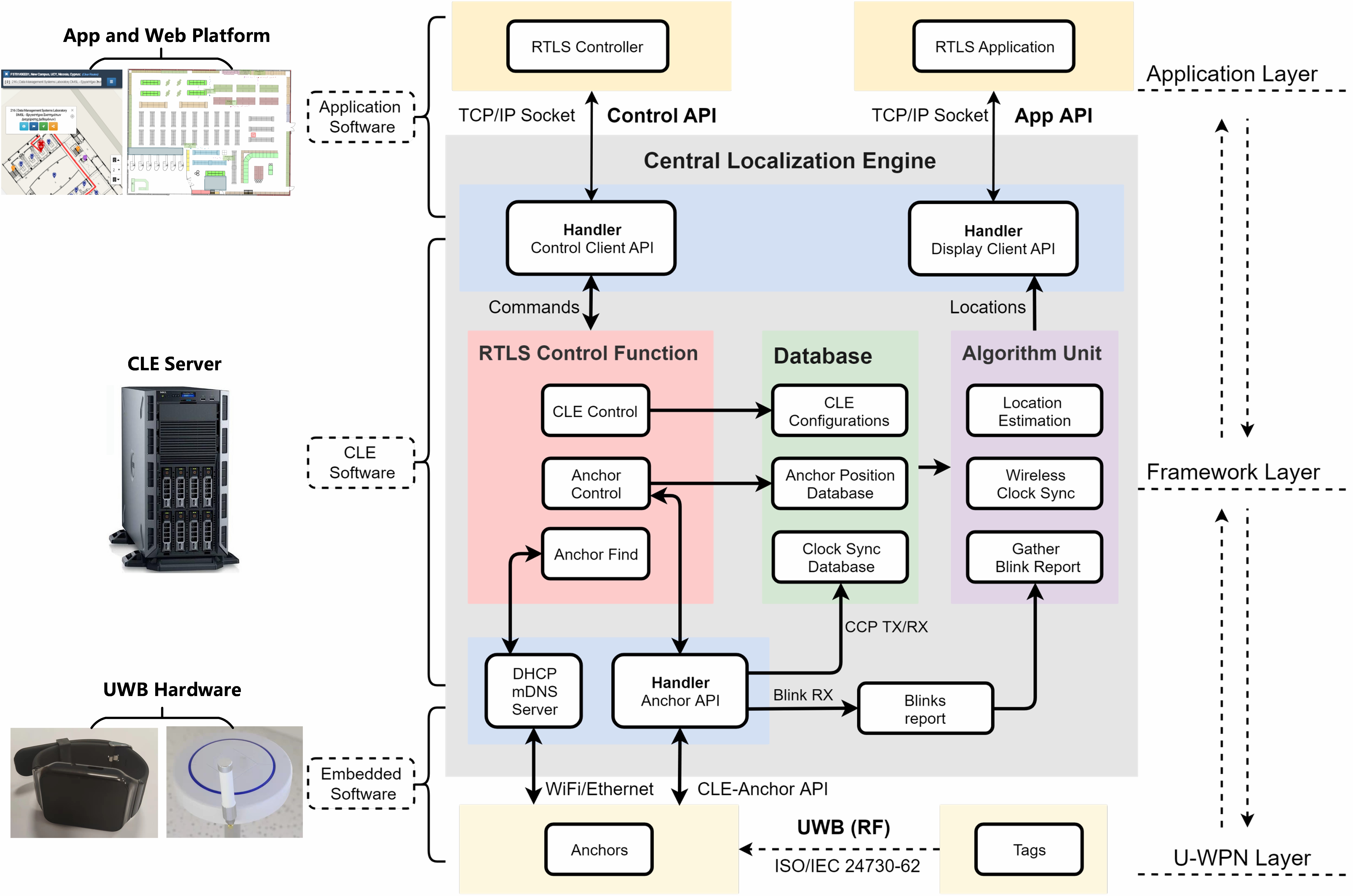
We have completed the development of embedded software, CLE software and application software. Figure 1 below gives a detailed view of the architecture of real-time localization system. The UWB based RTLS can be regarded as a three-layer architecture, including application layer, CLE framework layer, and the U-WPN layer. UWB anchors and tags are working at the U-WPN layer, and the UWB messages could be transmitted between them through ISO/IEC defined protocol. The CLE has a control function unit, a database, and an algorithm unit, which realizes the function of wireless clock synchronization and location estimation. Mobile apps and Web platforms could interact with the CLE framework layer through the open APIs.
3.2 UWB-based Wireless Positioning Network
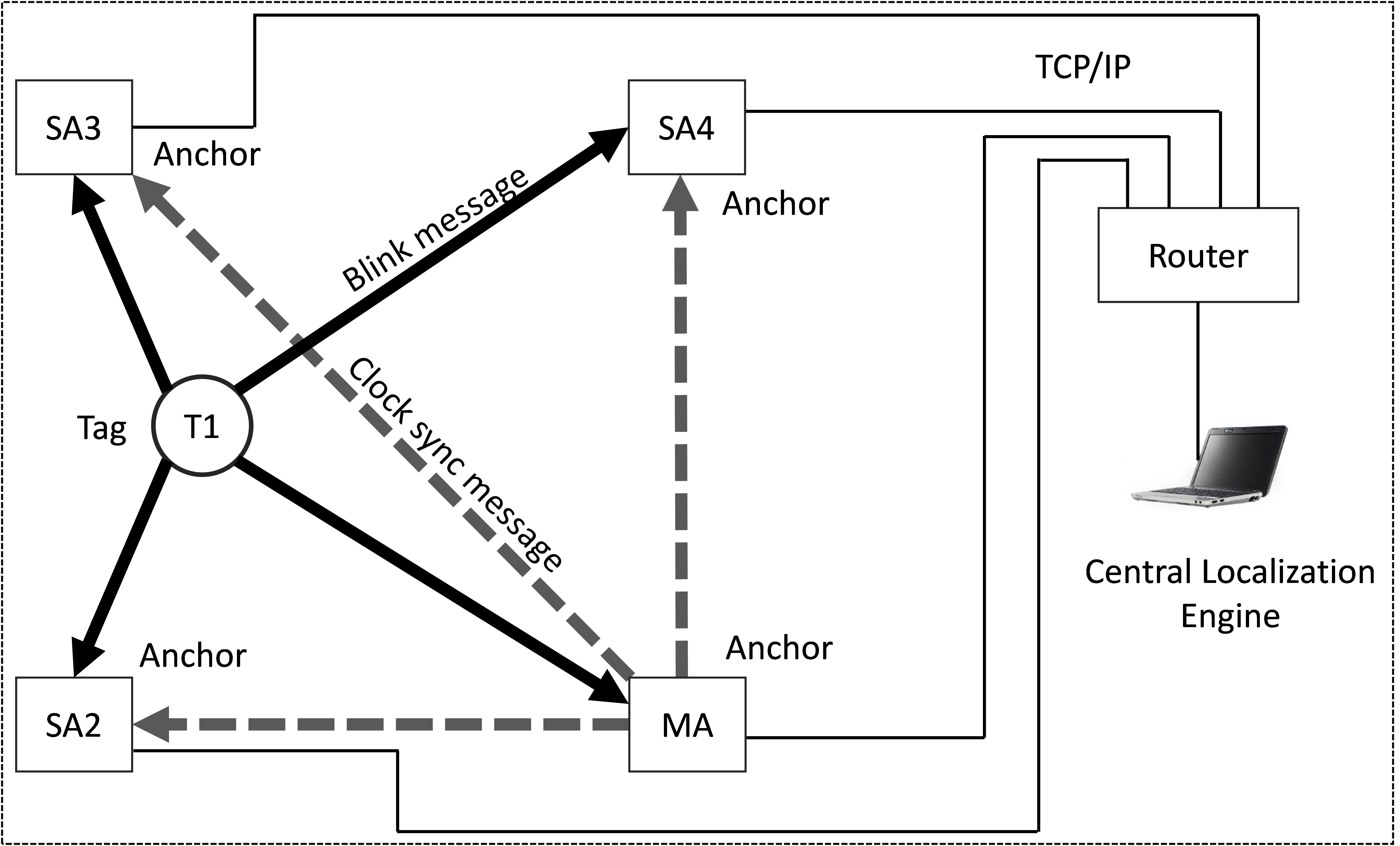
Figure 2 demonstrates the UWB-based Wireless Positioning Network (U-WPN) , which exchanges the UWB messages and Ethernet communication for a system with four Anchors, one Tag, and one CLE (Central localization engine). MA is the master anchor, and SA2, SA3, SA4 are the slave anchors. T1 is the Tag, and the CLE runs on an upper computer. The Tag transmits a periodic blink frame, which is received and timestamped at the anchors. Each anchor then sends the ToA reports to a Central Localization Engine (CLE), and the CLE uses the ToAs to estimate the Tag’s location. Tags periodically send "blink" messages, which are received by all anchors in the range.
To ensure that the ToAs recorded by the anchors are on the same reference clock, we need to eliminate the clock offset and drift of anchors. It is called clock synchronization and is typically achieved via wired clock distribution to the anchors. As an alternative to using a wired timer, the TDoA based RTLS designed in this paper includes a wireless clock synchronization algorithm that employs UWB messages sent between anchors to correct clock drift and offset.
Anchors can be configured as Master anchors (MA) and Slave anchors (SA). MA transmit Clock Calibration Packets (CCP) periodically. Slave anchors receive these CCP and report their reception to the CLE to track the relative clock offset between the sending master anchors and the receiving slave anchors. If an RTLS has more than one master, which could be called multiple masters based RTLS. A "secondary" master can delay sending its CCP by a configured lag time after the reception of a CCP from a "primary" master anchor to prevent from CCP collisions between CCP transmissions.
The purpose of clock synchronization is to record each anchor’s clock and calibrate the blink message timestamps to a recorded timestamp. The CLE also performs the TDoA algorithm to estimate the tags’ locations.
4 Wireless Clock Synchronization
Each UWB device equips with a high-resolution timer. The oscillation frequency will drift over time, and we must eliminate the effects of drift by clock calibration. The clock frequency offset and instability significantly impacts positioning accuracy in RTLS. Most of the RTLS utilize time measurement to get ToA or TDoA, which is used for position calculation. All the anchors need to be synchronized, as the precise timestamp is essential for location estimation. Three main issues should be addressed in synchronization (Lee et al., 2011):
-
•
Offset synchronization – Ensure the recorded timestamp between anchors using the same reference time;
-
•
Drift compensation – Eliminate frequency deviation caused by temperature and other environmental factors.
-
•
Antenna delay calibration – Eliminate the changes of different UWB devices’s internal propagation delay.
The measurement delay in the timestamp includes transmitting antenna delay and receiving antenna delay. These antenna delays are specifically internal to the chip and have not been included in time of flight (ToF). The solutions proposed in (Gui et al., 2018; Djaja-Josko and Kolakowski, 2016b) can be used for antenna delay calibration.
The wired clock synchronization scheme is an universal solution. However, additional clock synchronizing timer and transmission lines add to the difficulty of anchor deployment, so it is not suitable for complex environments. Hence a wireless clock synchronization solution without extra equipment is urgently needed. The method proposed in (Djaja-Josko and Kolakowski, 2016b) relies on the pair of packets and a known recorded timestamp, which uses the remained nodes’ corrected timestamps to carry out WCS. Meanwhile, a simple clock model is used in (Tiemann et al., 2016) for wireless clock correction, based on the offset and the drift. It is necessary to retain clock models for each anchor. (McElroy et al., 2014) proposes a clock synchronization scheme that can be used in multilateral systems based on a reference anchor placed at a known fixed location.
Clock offset correction is easier to solve when we know each anchor’s reference clock’s deviation, but the clock drift is not easy to eliminate due to the different clock modules in the anchors. Figure 2 depicts a basic UWB-based Wireless Positioning Network U-WPN in Section 3. We will use the U-WPN to introduce our proposed wireless clock synchronization scheme in this section.
Each Anchor and Tag have its own timer, and they are un-synchronized. The exact clock information of another device is unknown, which can only be obtained through a timestamp. Besides, the precise distance between the sending device and the receiving device is unknown. If all the slave anchors could receive the CCPs sent by one master anchor, so we adopt the scheme of WCS with a single master. If the CCP sent by a master anchor cannot be received by all slave anchors, multiple master anchors need to be deployed in the location area. In that case, the WCS with multiple masters need to be adopted for completed coverage.
4.1 WCS with a single master
The overall diagram of WCS with a single master is demonstrated in Figure 3, which shows our proposed positioning system receiving and sending positioning and synchronization messages on the timeline. T is tag, MA is a master anchor and SA2-SA4 are slave anchors. There are five timelines, with the top one representing the Tag and the bottom four belonging to the individual anchors. The dark dashed lines represent the positioning packet (Blinks) sent by the Tag with a sending period of 1s, while the light dashed lines represent the synchronous packet (CCPs) sent by the master anchor at an interval of 150ms.
Once the Tag sends the Blink or the master anchor sends the CCP, the slave anchors in the corresponding deployment area will receive the Blink or CCP and record the timestamp in the anchor’s clock system respectively. For the master anchor, in addition to receiving the Blink from the Tag similar to a slave anchor, it is also necessary to periodically send the CCP and record the sending timestamp.
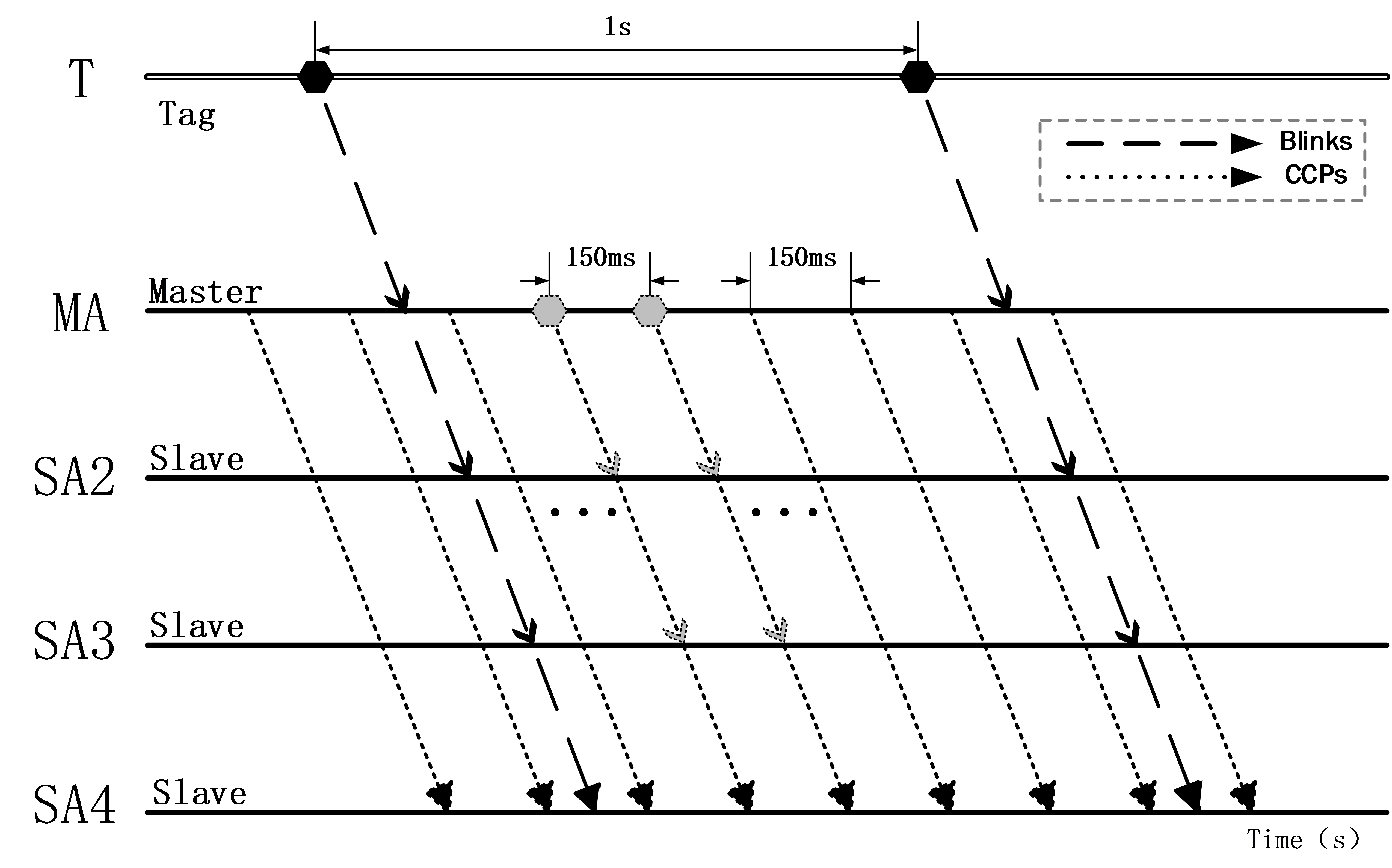
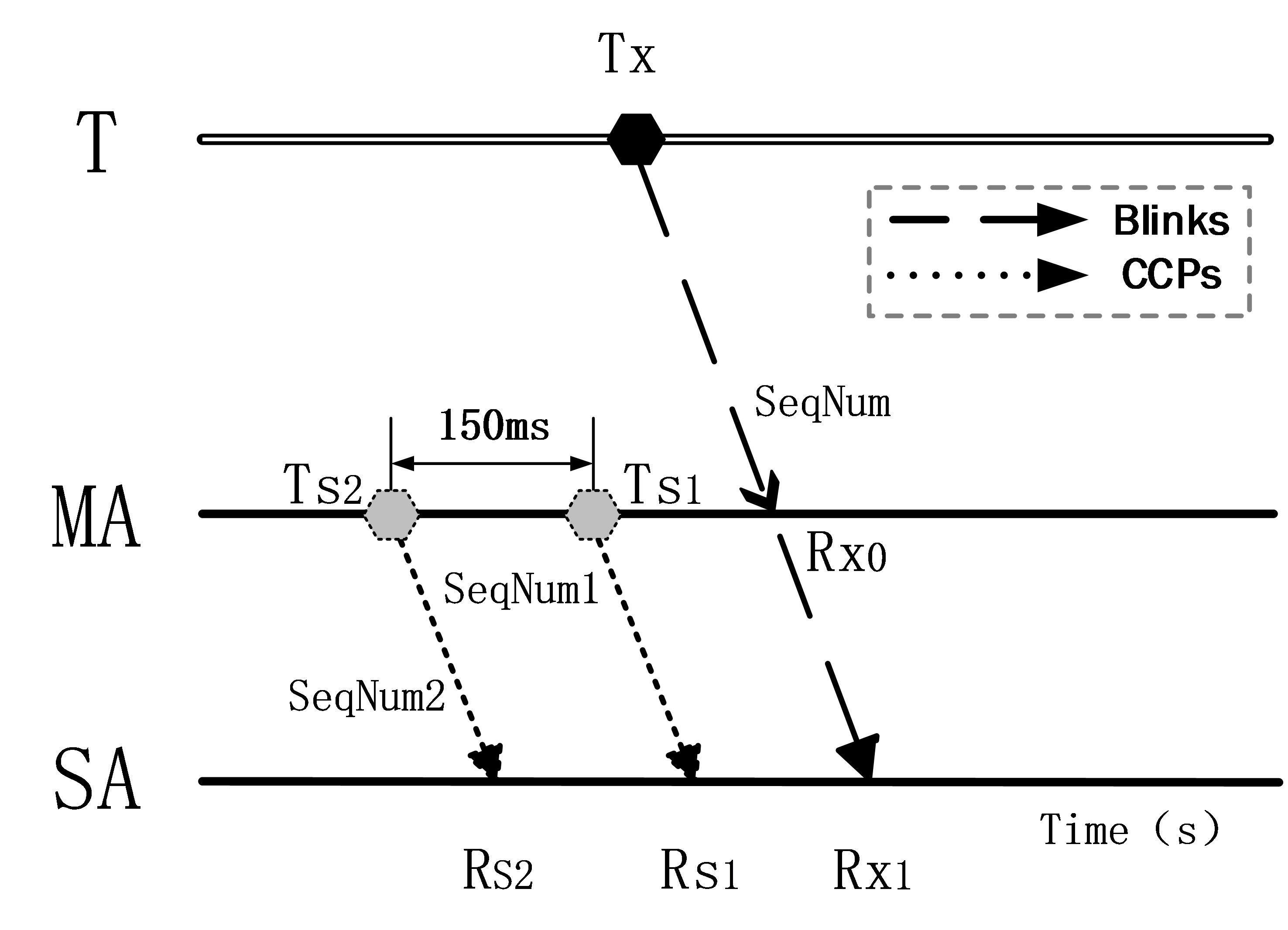
To illustrate the process of clock synchronization in detail, we use a simple case with one tag (T), one master anchor (MA), and one slave anchor (SA), as shown in Figure 3. After receiving the Blink, MA and SA will record the received timestamp (, ) and serial number (SeqNum) of this Blink. Meanwhile, the MA will record the sending timestamp (, ) and the corresponding serial number (SeqNum1, SeqNum2) when it sends the CCP. When the CCP reaches the SA node, the timestamp (, ) and the corresponding serial number will also be recorded.
The system clock drift caused by quartz crystal illustrates a certain regularity, so we build a scale coefficient model to correct the clock drift. As shown in Figure 4, an original TDoA can be expressed as: , and the scale coefficient of calibration can be set as .
| (1) |
The corrected TDoA is :
| (2) |
where, and are the timestamps recorded by SA and MA when they receive a Blink, and are the timestamps recorded by SA when it receives the CCPs, and are the timestamps recorded by MA when it sends the CCPs. Finally, the Kalman filters will be adopted to track each anchor’s clock offset after gathering all the . Based on this scheme, the clock of each anchor can be synchronized.
4.2 WCS with multiple masters
The overall diagram of WCS with multiple masters is demonstrated in Figure 5, including one primary MA (MA1), five secondary MAs (MA2-MA6), and nineteen SAs. The CCPs between anchors (MA and SA, or MA and MA) are in dotted lines. The deployment of MAs has been made to ensure that all secondary master anchors can communicate with the master anchor of the upper level, and any slave anchor can receive the synchronization signal of at least one master anchor. The rest part of this section describes in detail how the WCS scheme with multiple masters works.
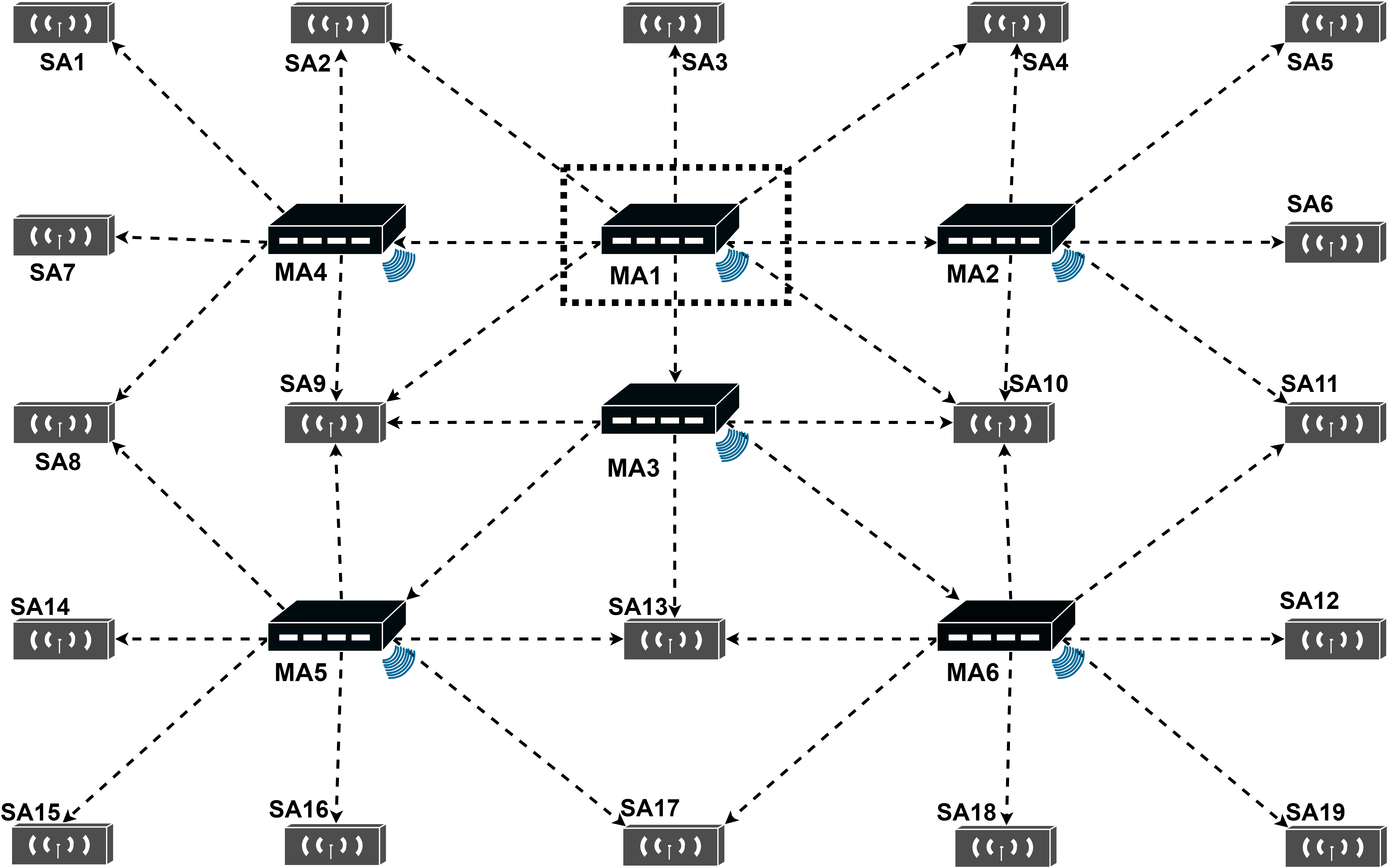
In order to cover a large area, it is necessary to employ more than one MA, where each MA is used as a reference to correct the clock drift of its neighboring SAs. We establish a multi-level cascade topological structure of the MAs to coordinate the order of sending CCPs between the primary MAs and the secondary MAs in a complete clock synchronization.
MA1 is the primary master anchor. Any MA receiving the CCPs sent by MA1 is the secondary master anchor. In addition, the MA receiving the CCPs of the secondary master anchor is level-3 master anchor. So, MA2, MA3 and MA4 are secondary master anchors, and MA5 and MA6 are Level-3 master anchors. According to this rule, the cascading model of MA can be obtained as follows: primary master anchor secondary master anchor level-3 master anchor level-4 master anchor level-N master anchor. When a lower level master anchor receiving the CCP from its upper level master anchor, it starts to send the CCP after a short interval (Lag).
Using Figure 5 as an example to illustrate WCS with multiple master anchors. Surrounding the primary master anchor (MA1) are three secondary master anchors (MA2, MA3, MA4) and five slave anchors (SA2, SA3, SA4, SA9, SA10), and they are configured to follow MA1, so their clocks need to be synchronized with MA1. There are five slave anchors (SA1, SA2, SA7, SA8, SA9) around the secondary master anchor MA4, and the slave anchors are configured to follow MA4, so their clocks could be synchronized with MA4. The slave anchors could be configured to follow more than one master anchors, such as SA2, SA3, SA4, SA8, SA9, and SA10.
Based on the topology of multi-level master anchor scheme, We summarize the strategies of WCS with multiple masters:
-
•
Setting every master anchor to send CCPs in a specified interval;
-
•
Choosing one master anchor as the primary master anchor (There is one and only one primary master anchor in a RTLS);
-
•
Setting the rest of master anchors as different levels;
-
•
Setting the lower level master anchors to follow its upper level master anchor;
-
•
Setting the lower level master anchors to send CCPs with different Lags to avoid the collision (for example, MA2 delay one Lag, MA3 delay two Lags, and MA4 delay three Lags);
-
•
Setting the slave anchors to follow the master anchor (Ensure the slave anchors could receive the CCPs sent by its master anchor);
-
•
Collecting the recorded ToAs of all the anchors and the transmiting timestamps of master anchors;
-
•
Using the WCS method shown in Section 4.1 to synchronize the TDoAs.
5 Location Estimation Based on TDoA
5.1 Model
TDoA based localization is a common approach used in the UWB system. The positioning system includes several anchors and tags. Assume there is only a single tag to be localized. The tag transmits signals to the anchors periodically. The model of TDoA can be expressed in Figure 6.

The tag could transmit the positioning frame to the anchors, and propagate in a straight line to the anchors (Line of sight condition should be satisfied, LoS). For two-dimension positioning, assuming that is the coordinates of the target, where are the coordinates of anchors, and are the distances between the tag and anchors.
We could get the timestamp when the frame is received by the anchors. Assuming that the measurement of satisfies . The core formula of TDoA is
| (3) |
where is the speed of light, the range differences (RD) represent the TDoA measurements, and the distance of here satisfy .
The aim is to find , so
| (4) |
where .
The inputs of the method are the anchors’ coordinates, , the measured TDoA, , and the outputs are the coordinates of the tag, .
Because of the measurement error, the least square condition is usually considered to estimate the position .
| (5) |
This is a non-convex optimization problem. So the EKF method could be adopted to solve this problem.
5.2 The algorithm of EKF
Location estimation through EKF is available in Khan et al. (2013), a constant velocity model is selected to describe the RTLS designed in this paper. The state equations and update equations of the EKF model are illustrated in the following formulas. The inputs of EKF include the range difference (RD) , the coordinates of anchor , and the initial position of the Tag . Meanwhile, the state transfer matrices and other covariance matrices used in the EKF algorithm could be calculated through the references Tiemann et al. (2016) and Khan et al. (2013).
-
[a.]
-
1.
The process model
-
2.
Time Update (“Predict”)
-
3.
Measurement Update (“Correct”)
Where
-
•
is the true state vector, , where, and represent the coordinates of the tag’s position , and represent the velocities along the x and y directions;
-
•
is the observation vector, and is the observation vector which can be defined as:
-
•
a priori state vector of a posteriori estimated state vector , where can be calculated by formula (5);
-
•
represents the process noise, and represents the observation noise vector;
-
•
is the input matrix, and is the input to the system;
-
•
is the estimated covariance matrix, and is the Kalman gain martix;
-
•
represents the covariance matrix, and represents the covariance matrix related to the observation vector;
-
•
represents the linearized state transition matrix, which can be defined as follows:
-
•
represents the Jacobian matrix related to expected measurements, which can be defined as follows:
where is the estimated Euclidean distance between the tag and the i-th UWB anchor, and is the estimate position which is defined at formula (7).
The details of the location estimation method based on EKF is demonstrated in Algorithm 1.
6 Time-base Selection Strategy and Anchor Deployment Scheme
6.1 Time-base Selection Strategy
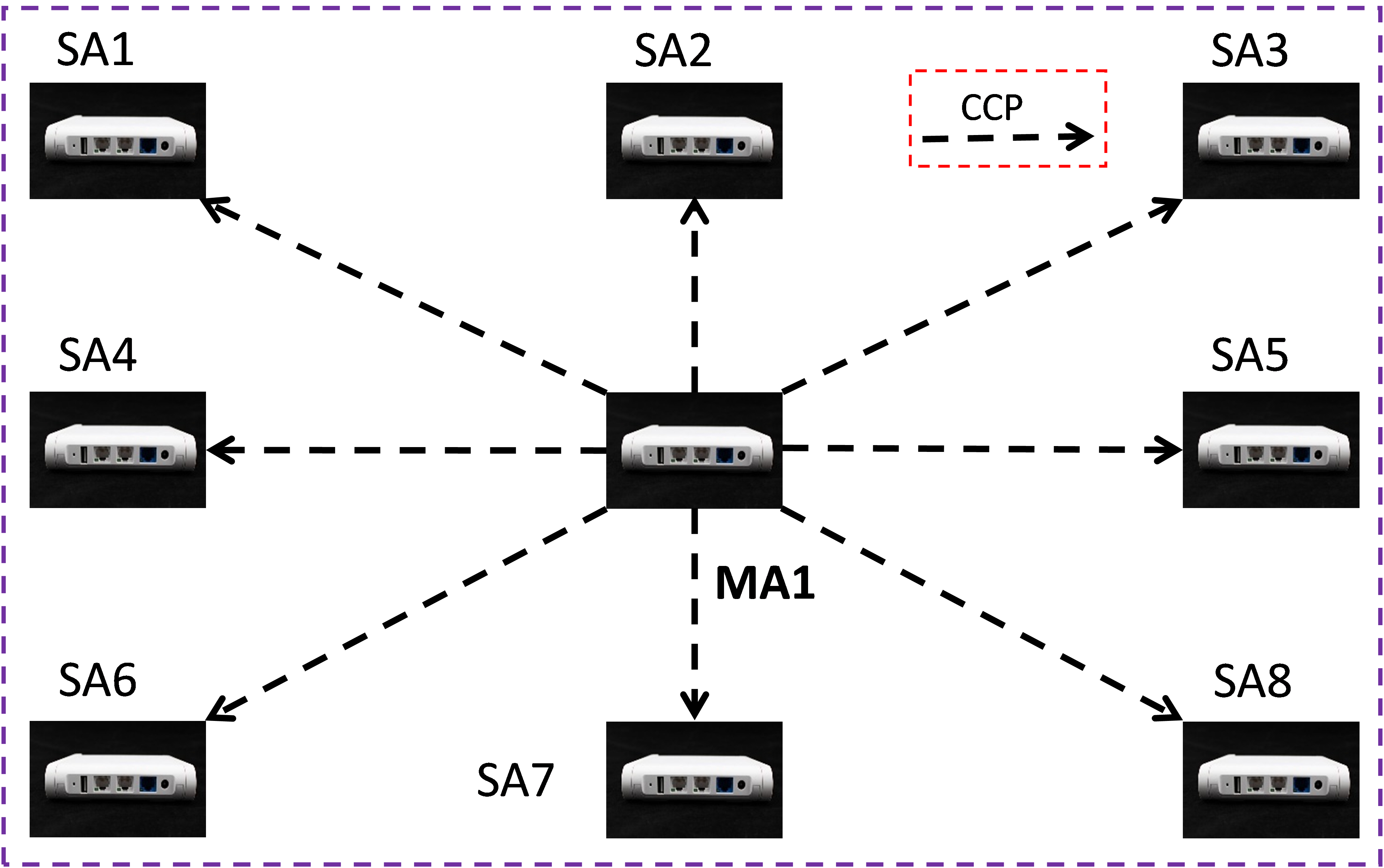
We need time-base selection strategy to cover different anchor deployment schemes in the TDoA-based real-time localization system, where time-base means the reference anchor’s ToA which will be selected to get the TDoA (). The anchor deployment based on WCS with a single master is illustrated in Figure 7, we choose the recorded timestamp of the single master anchor, MA1, as the time-base of TDoA.
We define the time-base selection rules with multiple master anchors as follows:
-
•
If the CCP received by a SA came from a same MA, the recorded timestamp of the MA is selected as the time-base of TDoA.
-
•
If the CCP received by a SA came from two or more MAs, then the recorded timestamp of the SA is selected as the time-base of TDoA.
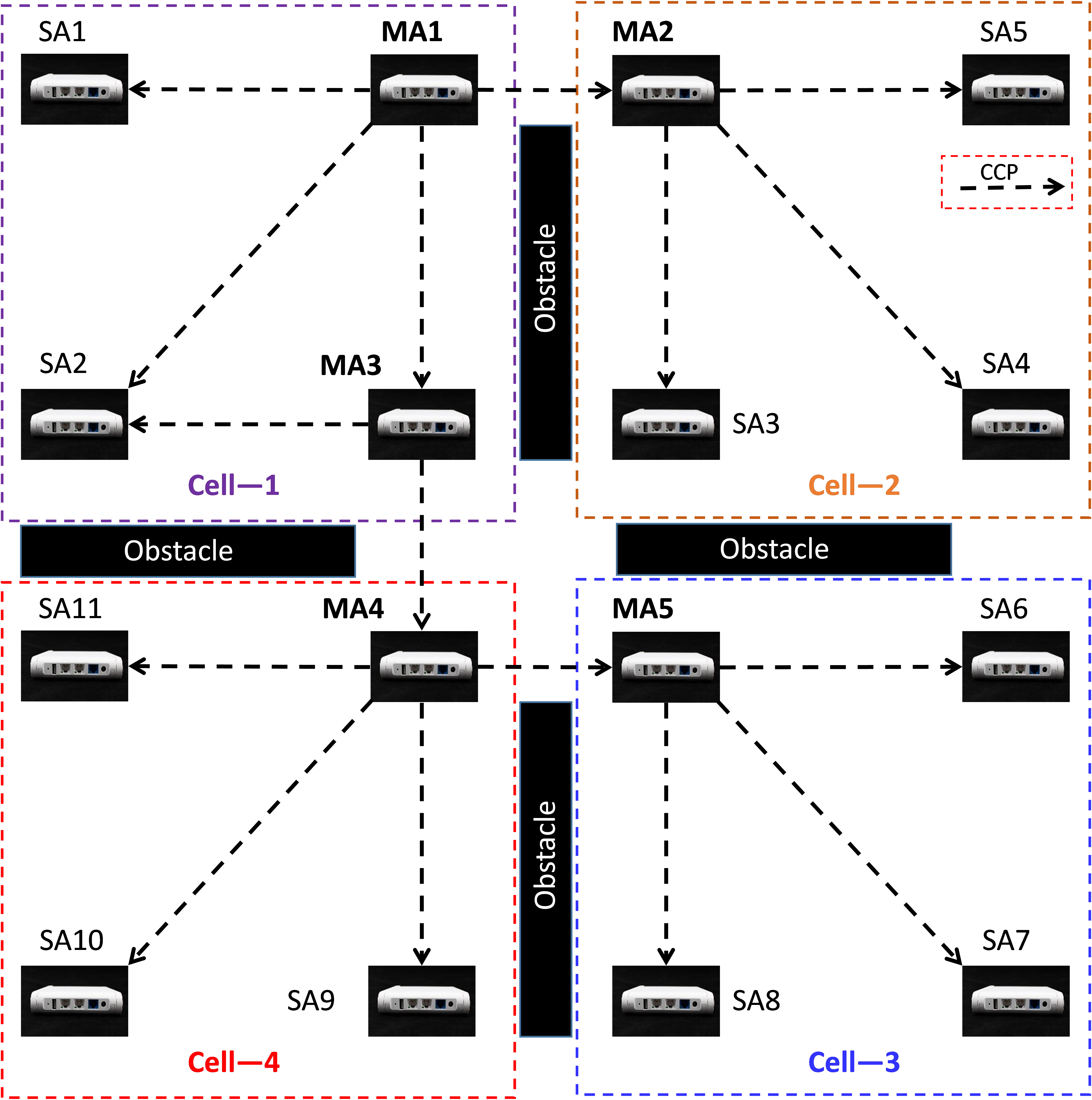
As an example, the anchor deployment based on WCS with multiple masters is demonstrated in Figure 8, when the Tag is located in Cell-1, SA2 could receive the CCPs from both MA1 and MA3, so the recorded timestamp of SA2 is selected as the time-base of TDoA; when the Tag moves to Cell-2, the SAs in this region can only receive CCPs from MA2, so the recorded timestamp of MA2 is selected as the time-base of TDoA.
6.2 Anchor Deployment Scheme
In a real deployment scenario, the necessary deployment rules need to be followed to ensure positioning accuracy. Corresponding to the two WCS schemes proposed in Section 4, we present two typical reference deployment schemes in practical scenarios.
The anchor deployment based on WCS with a single master is illustrated in Figure 7. We consider the case of a single master anchor covering a larger area, so the number of anchors go up to eight. Besides, to ensure smooth communication between the master anchor and all the surrounding slave anchors, we put the master anchor at the center of the positioning area.
In Figure 8, we discuss the situation of the location area with multiple master anchors. To make it easy to describe, we assume that the tracking space is divided into four separate areas, including one primary master anchor MA1, four secondary master anchors, MA2-MA5, eleven slave anchors, SA1-SA11. The dotted line indicates the CCP, representing the synchronous message. In the case of the current reference anchor deployment, the WCS with multiple masters scheme is adopted.
6.3 Common Deployment Rules:
The following seven rules extracted from our experiments should be considered when deploying the anchors.
-
[a.]
-
1.
Keep a LoS (line of sight) between a master anchor and slave anchors (at least 3 slave anchors).
-
2.
The anchors should be installed above the localized objects. Assure a clear line of sight between tags and anchors. Do not hide the Tag behind materials that attenuate the radio signal like water, a human body, or metal parts.
-
3.
Mount anchors (surrounding Master anchor) ideally at the same height (keep a variation of 1 meter maximum).
-
4.
Keep anchors detached away from walls or ceilings (ideally 50 cm but not less than 15 cm – shorter detachment may cause higher signal attenuation and inaccuracys due to reflections).
-
5.
Keep a square geometry when designing anchor deployment. The minimum distance between anchors should be longer than 3 meters. The location area should be bigger than 3m x 3m.
-
6.
Orient the anchors such that their radiation capabilities are satisfactory.
6.4 Dilution of Precision (DoP) Guided Deployment
The DoP model could be used for evaluating the relationship between the anchors’ placement geometry with the positioning accuracy of the RTLS. The DoP model could be adapted to measure various positioning systems’ performance and is independent of communication technologies and modes. We have studied the DoP for the TDoA technique with respect to anchor deployment in (Zhang et al., 2021).
The DoP provides a gain factor that is numerically dimensionless and represents the relationship between the measurement error at a given position and the geometry of the anchors. It should be noted that the relationship between anchor spacing and DoP is fragile, but their geometric structure will have a specific influence. So it’s worth discussing how to deploy anchors based on the DoP. We can adopt the most practical horizontal DoP (HDoP) because 2-D positioning is used much more frequently than 3-D positioning in most scenarios. This work mainly take square anchor geometry as suggested by.
7 Experiments and Performance Analysis
7.1 Introduction of the Experimental Environment
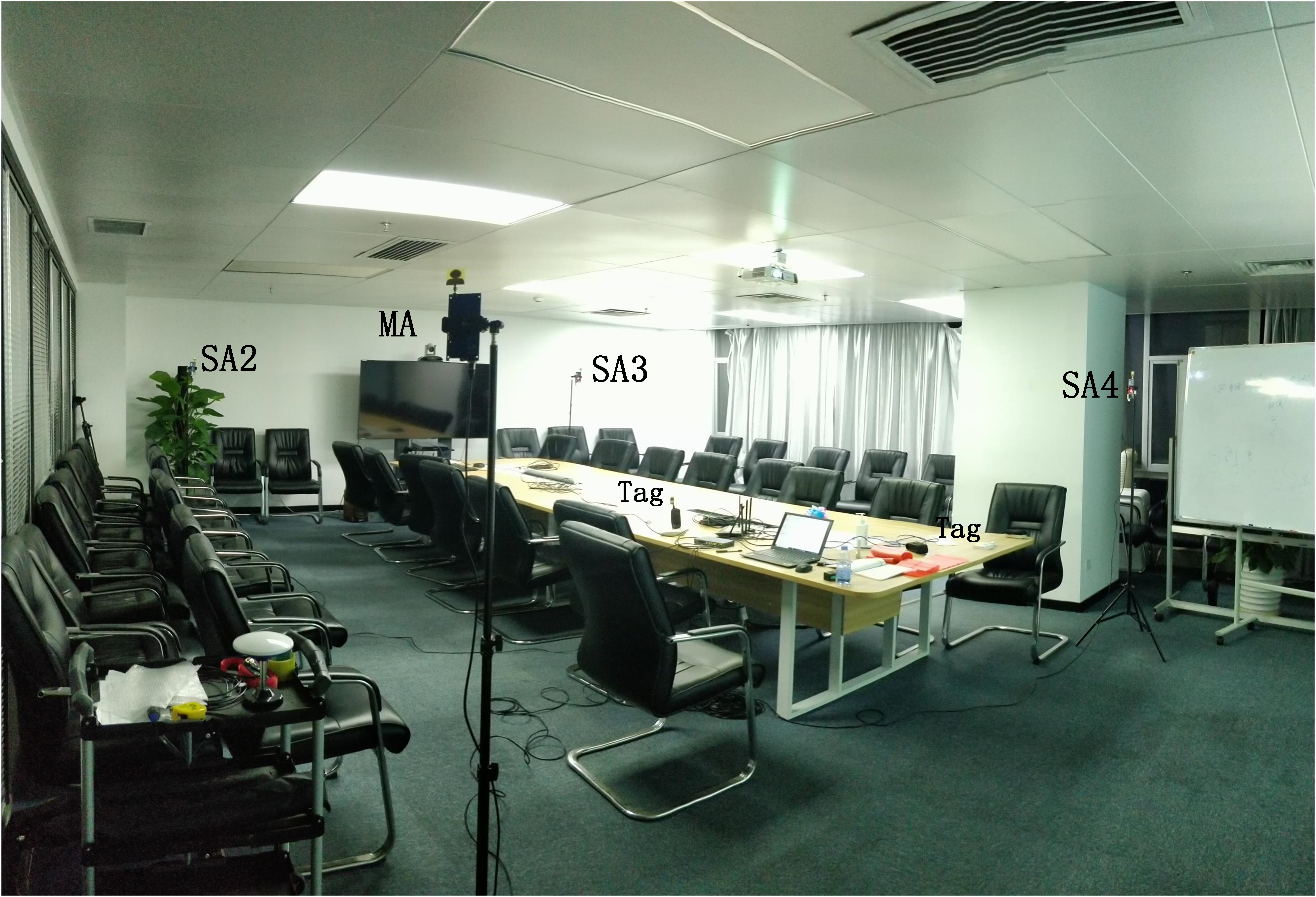
According to the UWB-based Wireless Positioning Network (U-WPN) proposed in Section 3, a test experiment is set up to analyze the proposed approach’s positioning accuracy and stability, which is shown in Figure 8. We deploy four anchors in a conference room. They are fixed on the four vertices of a rectangle with 6m’s length and 4m’s width. The RTLS we have built includes four anchors, two tags, one router, one PoE Switch, and a CLE. The test process is as follows: Four anchors are fixed on the tripods with the same height of 1.80m. The sending periods of CCP and Blink are set respectively.
-
•
A CCP is transmitted from the master anchor every 150 milliseconds.
-
•
A blink is transmitted from the Tag every 100 milliseconds.
7.2 Performance of WCS Scheme with a Single Master Anchor
The results of the WCS scheme with a single master anchor are shown in Figures 10 and 11. SA2-MA, SA3-MA, and SA4-MA represent the TDoA between the master anchor and three slave anchors respectively. It is obvious that, the original synchronized TDoA data demonstrated in Figure 10, are with large fluctuations and several nanoseconds synchronization errors. Such TDoA data cannot be directly used for precise positioning. We used the Kalman Filter (KF) to process the original synchronized TDoA data, and the results were illustrated in Figure 11. It is obvious that KF greatly reduces the influence of noise on the WCS scheme.
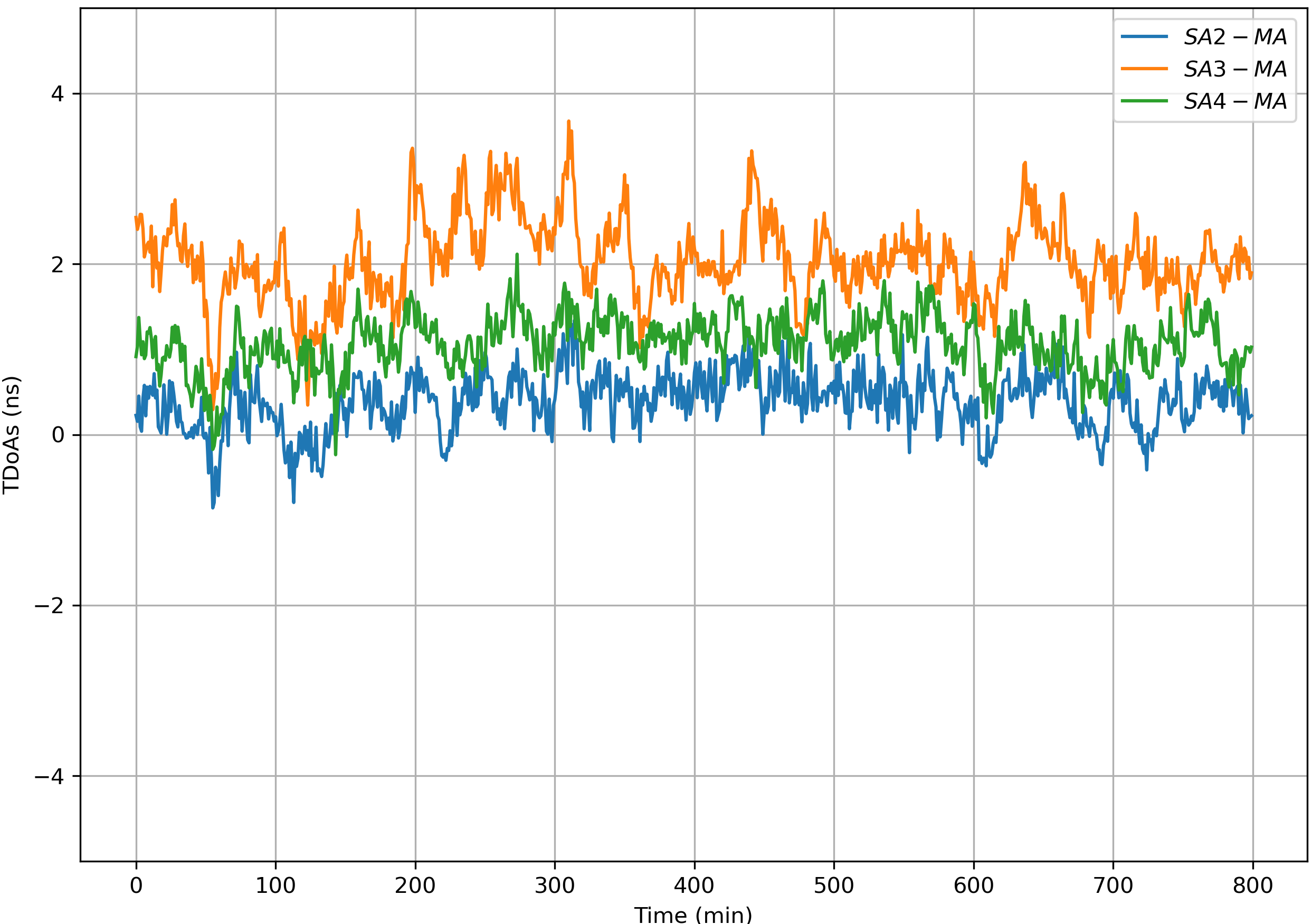
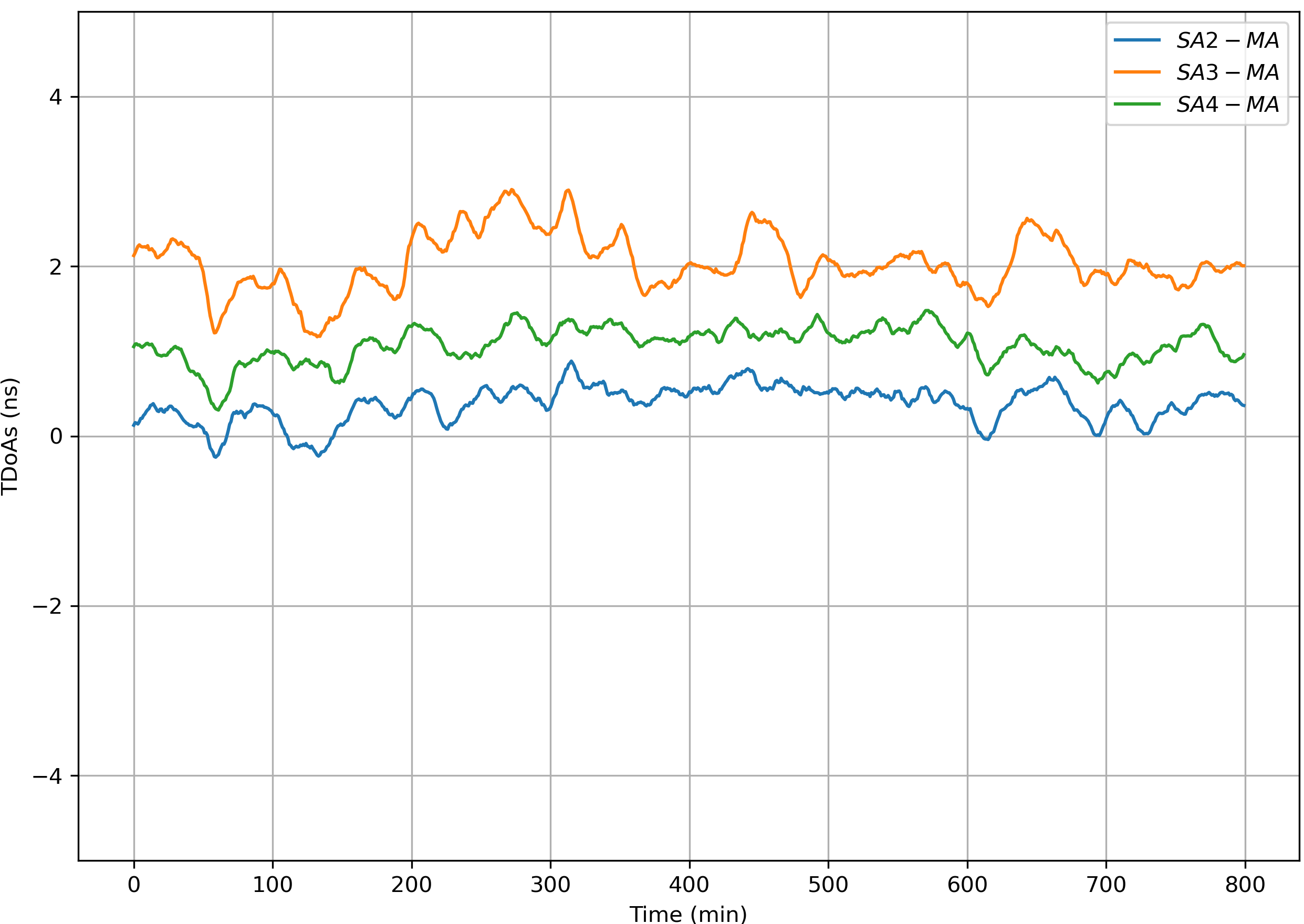
For each SA, the Blink RX timestamps are corrected with the wireless clock synchronization algorithm. The corrected timestamps, which follow its corresponding master recorded timestamp, are used for calculating the TDoA of each blink message between the MA and each SA. The standard deviations of the TDOA for the deployed three slave anchors in the test environment were 0.18 ns, 0.19 ns, and 0.14 ns throughout an 800-minute test. The average value of these deviations is not more than 200 ps, representing a standard deviation of position less than 6cm.
7.3 Performance of WCS Scheme with Multiple Master Anchors
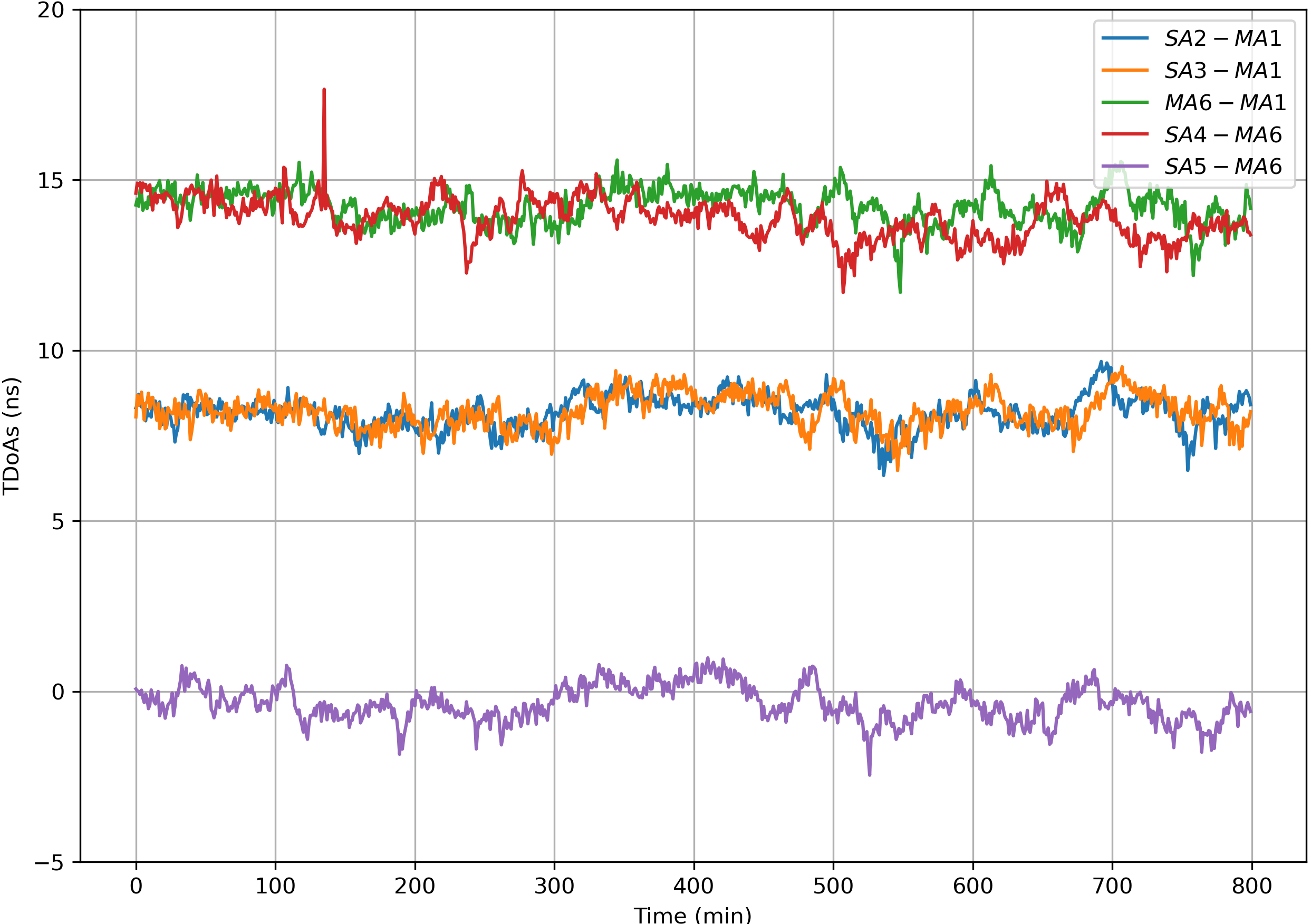
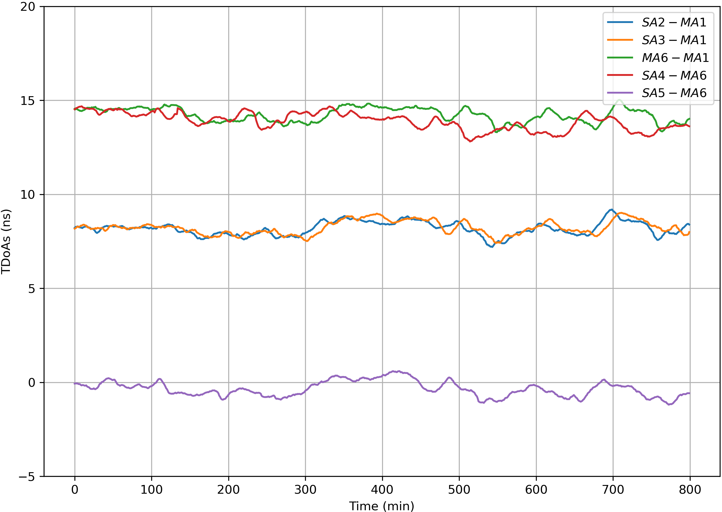
The results of the WCS scheme with multiple master anchors are shown in Figures 12 and 13. SA2-MA1, SA3-MA1, MA6-MA1, SA4-MA6, and SA5-MA6 represent the TDoAs between the master anchors and slave anchors respectively.The original synchronized TDoA data demonstrated in Figure 12, and the results after applied KF were illustrated in Figure 13.
7.4 Performance of RTLS with a Single Master Anchor
We use an extended Kalman filter (EKF) in the RTLS to estimate the tags’ positions, and the test results are demonstrated in Figure 14.
The test results of tag tracking with a single master anchor are illustrated in Figure 15.
7.5 Performance of RTLS with Multiple Master Anchors
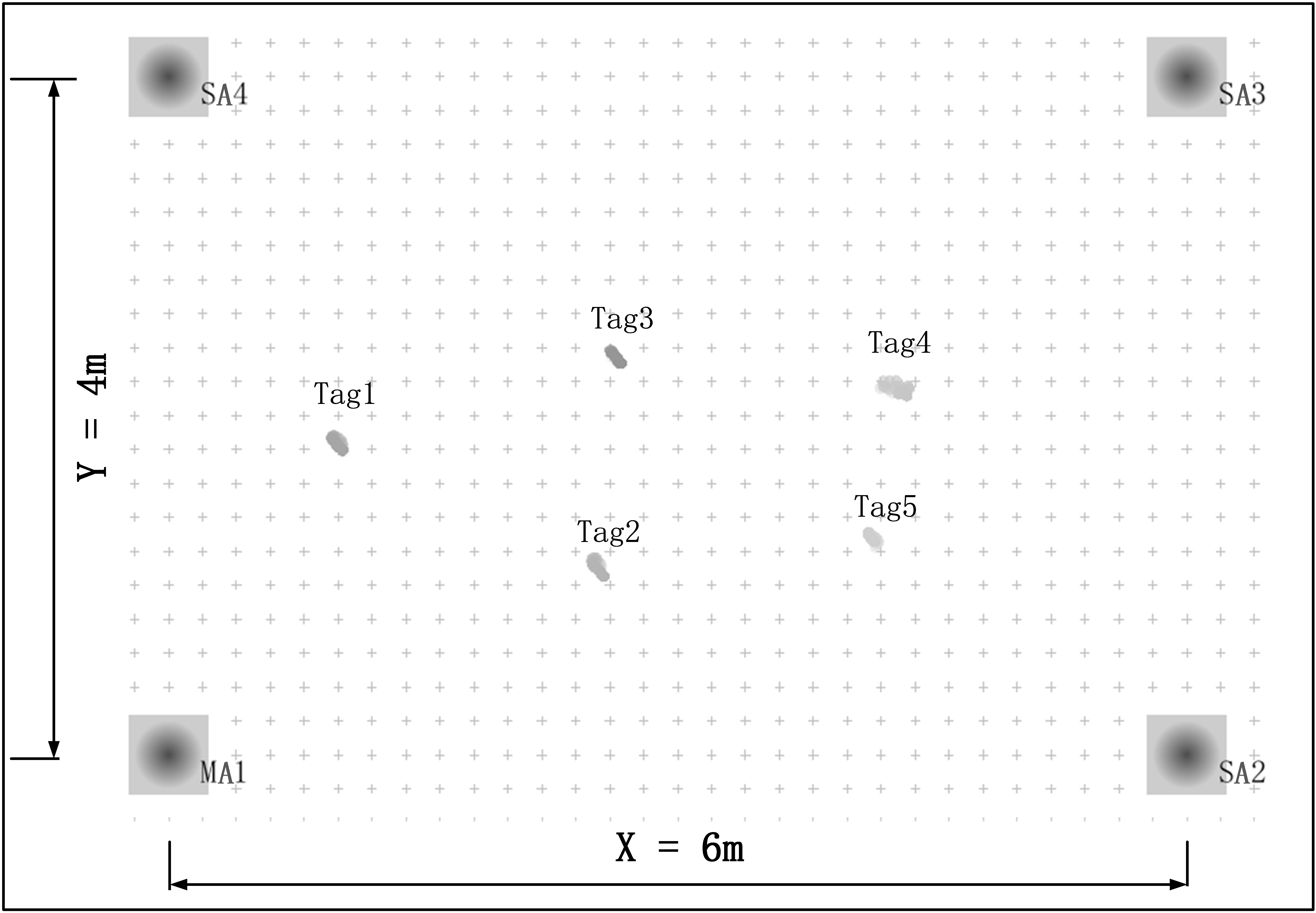
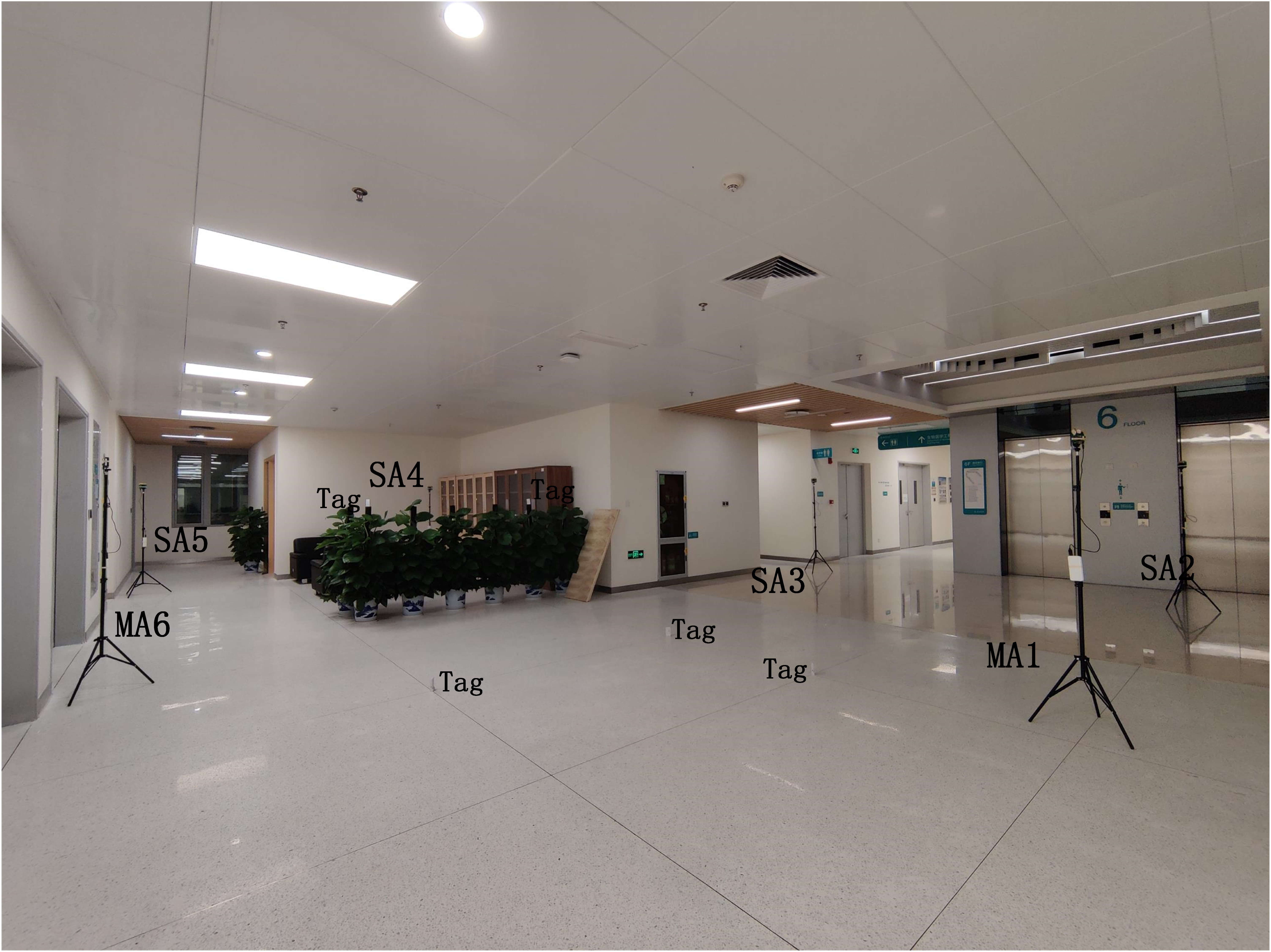
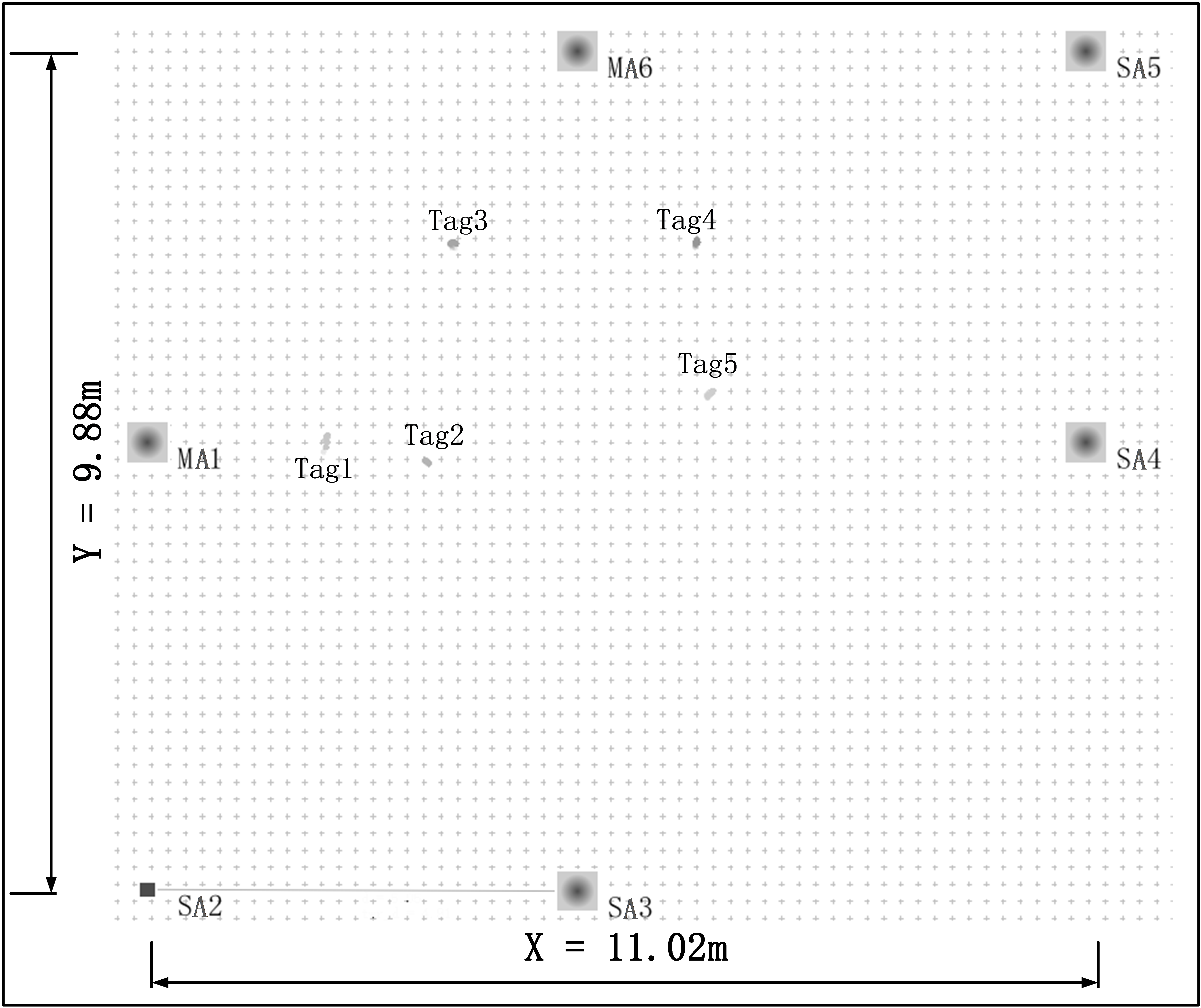
Another test experiment is set up to analyze the proposed approach’s positioning accuracy and stability, which is shown in Figure 16. The test is conducted in a 9.88-meter wide and 11.02-meter long Hall. We deploy two master anchors (MA1, and MA6) and four slave anchors (SA2, SA3, SA4, and SA5). Also there are 5 tags (Tag1, Tag2,…, Tag5) deployed in this area.
We use the RTLS built in this paper to estimate the tags’ positions in a static scenario, and the test results are demonstrated in Figure 17.
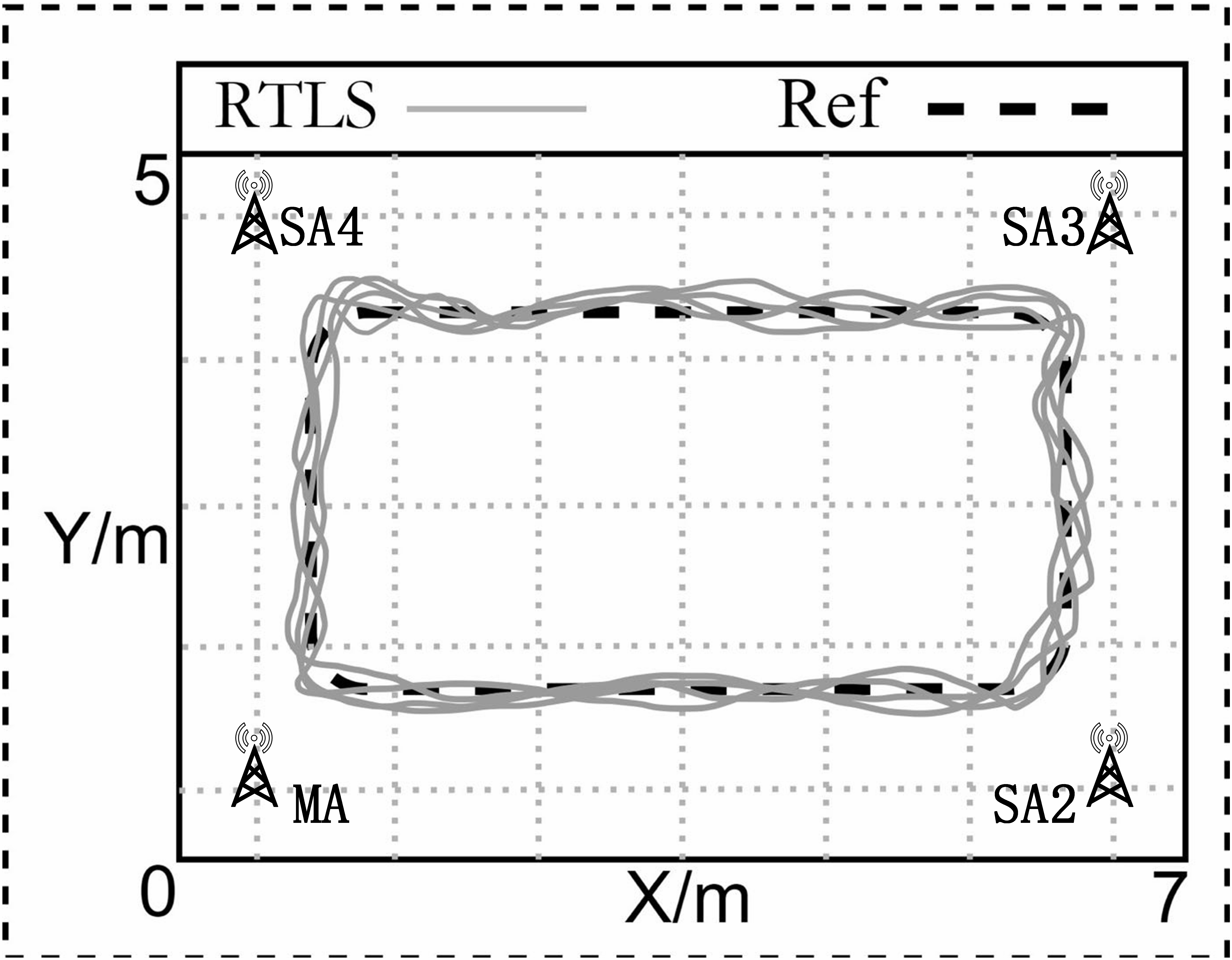
The test results of tag tracking with multiple master anchors are demonstrated in Figure 18.
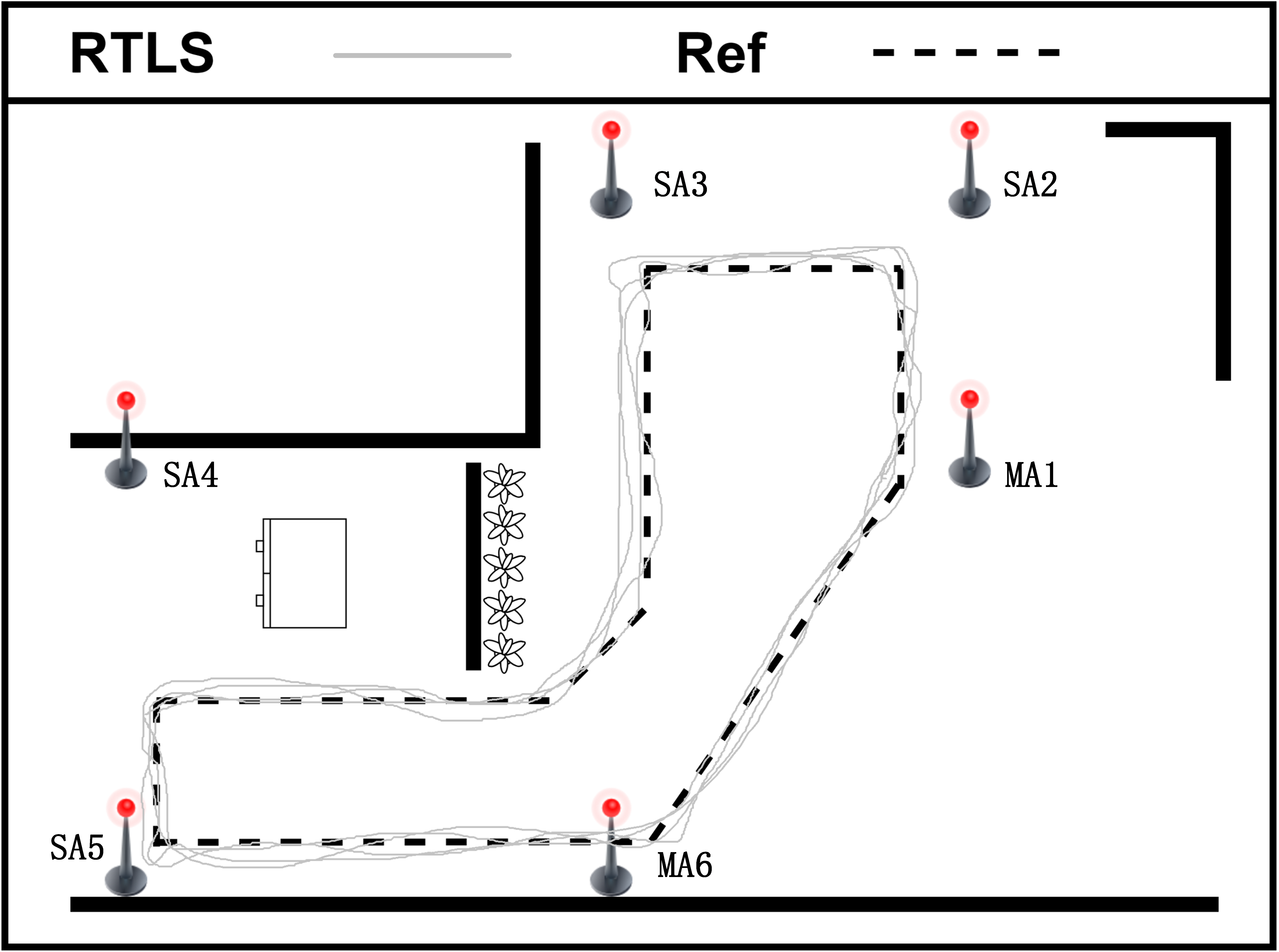
To illustrate the effectiveness of the adopted EKF scheme during static situation and tag tracking, we conduct the above experiments. The experimental results as shown in Figure 14, Figure 15, Figure 17, and Figure 18, illustrate that the RTLS designed in this paper has stable performance in tracking and has high positioning accuracy while ensuring positioning continuity. We can achieve less than 10cm the positioning error when the tag is fixed and less than 30cm when the tag is moving. Limited by the hardware’s clock resolution, it is hard to completely eliminate clock bias and positioning errors.
7.6 Comparison of Positioning Performance of Different Schemes
Table 1 demonstrates the positioning performance of eleven schemes using TDoA method. ATLAS’s sheme amd Bitcraze’s scheme are open source, and the other eight schemes are commercial. According to the data provided by each solution provider, the static positioning accuracy is about 10cm, and the dynamic positioning accuracy is about 30cm. Compared with our proposed scheme, the positioning accuracy is almost the same, because any mature solution uses unique algorithms to eliminate external errors, so the positioning accuracy depends on the performance of the UWB RF chip. The performance of our proposed scheme is consistent with the mainstream schemes, and it has flexible expansion in the aspect of multi-anchor cascade.
| Scheme | Source | Static | Dynamic |
| SUSTechRTLS | Lab Research | 5- 10cm | about 30cm |
| DecaWaveRTLS | Commercial | about 10cm | about 30cm |
| JINGWEI | Commercial | about 10cm | 10- 30cm |
| ATLAS | Open Source | about 10cm | 20-30cm |
| woxuwireless | Commercial | about 10cm | about 30cm |
| Bitcraze | Open Source | about 10cm | 10-30cm |
| EHIGH | Commercial | about 10cm | about 30cm |
| Sewio | Commercial | less 10cm | about 30cm |
| Localsense | Commercial | about 10cm | 10-30cm |
| zebra | Commercial | about 10cm | 10-30cm |
| ubitraq | Commercial | about 10cm | 10-30cm |
8 Conclusion and Future Work
This paper reviews the existing technologies and solutions for precise positioning, analyzes the advantages of UWB technology, discusses the current available solutions of mainstream manufacturers in UWB. Then we summarizes the algorithms and solutions needed to build a real-time localization system based on UWB. To address the deficiencies and challenges of the existing solutions, a comprehensive UWB-based RTLS is proposed.
First of all, we design and implement the hardware and software of anchors and tags based on UWB, which have good performance and low power consumption. Then, we propose the new wireless clock synchronization (WCS) method, and define the time-base selection strategy for TDoA algorithm in signal master anchor and multiple master anchors systems. Meanwhile, the EKF method for solving TDoA issues is introduced for nonlinear dynamic systems, and it is useful in moving target tracking with the real-time positioning accuracy up to 30cm. Finally, we discuss the relationship between anchor deployment and positioning accuracy.
At present, DW1000 chip follows the standard of IEEE 802.15.4-2011. Meanwhile, the IEEE 802.15.4z standard is announced to support DW3000, Apple U1, and NXP SR100T. The IEEE 802.15.4z defines new features based on the original standard, with enhanced security, lower power consumption, and longer transmission distance. We will continue our research based on the new standard, including TDoA, arrival of angle (AoA), and phase difference of arrival (PDoA).
Acknowledgment
This research is supported in part by the National Natural Science Foundation of China (Grant No. 92067109, 61873119); and in part by the Scientific Research Foundation of Science and Technology on Near-Surface Detection Laboratory of China (Grant No. TCGZ2018A006); and in part by the Science and Technology Planning Project of Guangdong Province(Grant No. 2021A0505030001); and in part by the Educational Commission of Guangdong Province (Grant No. 2019KZDZX1018).
References
- Al-Ammar et al. (2014) Al-Ammar, M.A., Alhadhrami, S., Al-Salman, A.S., Alarifi, A., Al-Khalifa, H.S., Alnafessah, A., Alsaleh, M., 2014. Comparative survey of indoor positioning technologies, techniques, and algorithms, in: 2014 International Conference on Cyberworlds, Santander, Cantabria, Spain, October 6-8, 2014, IEEE Computer Society. pp. 245–252. URL: https://doi.org/10.1109/CW.2014.41, doi:10.1109/CW.2014.41.
- Alarifi et al. (2016) Alarifi, A., Al-Salman, A.S., Alsaleh, M., Alnafessah, A., Alhadhrami, S., Al-Ammar, M.A., Al-Khalifa, H.S., 2016. Ultra wideband indoor positioning technologies: Analysis and recent advances. Sensors 16, 707. URL: https://doi.org/10.3390/s16050707, doi:10.3390/s16050707.
- Alwan and Hussain (2017) Alwan, N.A.S., Hussain, Z.M., 2017. Gradient descent localization in wireless sensor networks, in: Wireless Sensor Networks - Insights and Innovations, London, United Kingdom. p. 27–38. doi:10.5772/intechopen.69949.
- Barbieri et al. (2021) Barbieri, L., Brambilla, M., Trabattoni, A., Mervic, S., Nicoli, M., 2021. Uwb localization in a smart factory: Augmentation methods and experimental assessment. IEEE Transactions on Instrumentation and Measurement 70, 1–18. doi:10.1109/TIM.2021.3074403.
- Bottigliero et al. (2021) Bottigliero, S., Milanesio, D., Saccani, M., Maggiora, R., 2021. A low-cost indoor real-time locating system based on TDOA estimation of UWB pulse sequences. IEEE Trans. Instrum. Meas. 70, 1–11. URL: https://doi.org/10.1109/TIM.2021.3069486, doi:10.1109/TIM.2021.3069486.
- Chen et al. (2019) Chen, J., Shi, T., Liu, Y., Wu, S., 2019. A time-compensation tdoa-based wireless positioning method for multi-level iot positioning, in: 2019 15th International Wireless Communications Mobile Computing Conference (IWCMC), pp. 1731–1736. doi:10.1109/IWCMC.2019.8766539.
- Commission (2002) Commission, F.C., 2002. Revision of part 15 of the commission’s rules regarding ultra wideband transmission systems 65. URL: https://www.fcc.gov.
- Comuniello et al. (2020) Comuniello, A., Moschitta, A., Angelis, A.D., 2020. Ultrasound tdoa positioning using the best linear unbiased estimator and efficient anchor placement. IEEE Trans. Instrum. Meas. 69, 2477–2486. URL: https://doi.org/10.1109/TIM.2019.2958011, doi:10.1109/TIM.2019.2958011.
- Curran and Furey (2008) Curran, K., Furey, E., 2008. Pinpointing users with location estimation techniques and wi-fi hotspot technology. Int. J. Netw. Manag. 18, 395–408. URL: https://doi.org/10.1002/nem.683, doi:10.1002/nem.683.
- Decawave (2017a) Decawave, 2017a. Dw1000 datasheet—dw1000 ieee802.15.4-2011 uwb transceiver (datasheet for dw1000) URL: https://www.decawave.com/wp-content/uploads/2020/04/DW1000_Datasheet.pdf.
- Decawave (2017b) Decawave, 2017b. Dw1000 user manual—dw1000 ieee802.15.4-2011 uwb transceiver (datasheet for dw1000) URL: https://www.decawave.com/dw1000/usermanual/.
- Djaja-Josko and Kolakowski (2016a) Djaja-Josko, V., Kolakowski, J., 2016a. Application of kalman filter for positioning precision improvement in uwb localization system, in: 2016 24th Telecommunications Forum (TELFOR), pp. 1–4. doi:10.1109/TELFOR.2016.7818751.
- Djaja-Josko and Kolakowski (2016b) Djaja-Josko, V., Kolakowski, J., 2016b. A new method for wireless synchronization and tdoa error reduction in uwb positioning system, in: 2016 21st International Conference on Microwave, Radar and Wireless Communications (MIKON), pp. 1–4. doi:10.1109/MIKON.2016.7492077.
- Gui et al. (2018) Gui, X., Guo, S., Chen, Q., Han, L., 2018. A new calibration method of uwb antenna delay based on the ads-twr, in: 2018 37th Chinese Control Conference (CCC), pp. 7364–7369. doi:10.23919/ChiCC.2018.8483104.
- Herbruggen et al. (2019) Herbruggen, B.V., Jooris, B., Rossey, J., Ridolfi, M., Macoir, N., den Brande, Q.V., Lemey, S., Poorter, E.D., 2019. Wi-pos: A low-cost, open source ultra-wideband (UWB) hardware platform with long range sub-ghz backbone. Sensors 19, 1548. URL: https://doi.org/10.3390/s19071548, doi:10.3390/s19071548.
- Kempke et al. (2015) Kempke, B., Pannuto, P., Dutta, P., 2015. Polypoint: Guiding indoor quadrotors with ultra-wideband localization, in: Proceedings of the 2nd International Workshop on Hot Topics in Wireless, Association for Computing Machinery, New York, NY, USA. p. 16–20. URL: https://doi.org/10.1145/2799650.2799651, doi:10.1145/2799650.2799651.
- Khan et al. (2013) Khan, R., Sottile, F., Spirito, M.A., 2013. Hybrid positioning through extended kalman filter with inertial data fusion. International journal of information and electronics engineering 3, 127–131. doi:10.7763/IJIEE.2013.V3.281.
- Kim et al. (2010) Kim, E.C., Park, S., Cha, J.S., Kim, J.Y., 2010. Improved performance of uwb system for wireless body area networks. IEEE Transactions on Consumer Electronics 56, 1373–1379. doi:10.1109/TCE.2010.5606272.
- Lee et al. (2011) Lee, J.X., Lin, Z.W., Chin, P.S., Law, C.L., 2011. Non-synchronised time difference of arrival localisation scheme with time drift compensation capability. IET Commun. , 693–699doi:10.1049/iet-com.2010.0183.
- Li et al. (2011) Li, B., Zhou, Z., Li, D., Zou, W., 2011. A novel parzen probabilistic neural network based noncoherent detection algorithm for distributed ultra-wideband sensors. Journal of Network and Computer Applications 34, 1894–1902. URL: https://www.sciencedirect.com/science/article/pii/S1084804510002262, doi:https://doi.org/10.1016/j.jnca.2010.12.015. control and Optimization over Wireless Networks.
- McElroy et al. (2014) McElroy, C., Neirynck, D., McLaughlin, M., 2014. Comparison of wireless clock synchronization algorithms for indoor location systems, in: 2014 IEEE International Conference on Communications Workshops (ICC), pp. 157–162. doi:10.1109/ICCW.2014.6881189.
- Papapostolou and Chaouchi (2011) Papapostolou, A., Chaouchi, H., 2011. Rfid-assisted indoor localization and the impact of interference on its performance. Journal of Network and Computer Applications 34, 902–913. URL: https://www.sciencedirect.com/science/article/pii/S1084804510000834, doi:https://doi.org/10.1016/j.jnca.2010.04.009. rFID Technology, Systems, and Applications.
- Pease et al. (2017) Pease, S.G., Conway, P.P., West, A.A., 2017. Hybrid tof and rssi real-time semantic tracking with an adaptive industrial internet of things architecture. Journal of Network and Computer Applications 99, 98–109. URL: https://www.sciencedirect.com/science/article/pii/S1084804517303235, doi:https://doi.org/10.1016/j.jnca.2017.10.010.
- Pelka and Hellbrück (2016) Pelka, M., Hellbrück, H., 2016. Survey of challenges and towards a unified architecture for location systems. Journal of Network and Computer Applications 67, 75–85. URL: https://www.sciencedirect.com/science/article/pii/S1084804516000928, doi:https://doi.org/10.1016/j.jnca.2016.02.009.
- Pughat and Sharma (2017) Pughat, A., Sharma, V., 2017. Performance analysis of an improved dynamic power management model in wireless sensor node. Digital Communications and Networks 3, 19–29. URL: https://www.sciencedirect.com/science/article/pii/S2352864816300967, doi:https://doi.org/10.1016/j.dcan.2016.10.008.
- Sidorenko et al. (2020) Sidorenko, J., Schatz, V., Scherer-Negenborn, N., Arens, M., Hugentobler, U., 2020. Error corrections for ultrawideband ranging. IEEE Transactions on Instrumentation and Measurement 69, 9037–9047. doi:10.1109/TIM.2020.2996706.
- Tiemann et al. (2016) Tiemann, J., Eckermann, F., Wietfeld, C., 2016. ATLAS - an open-source tdoa-based ultra-wideband localization system, in: International Conference on Indoor Positioning and Indoor Navigation, IPIN 2016, Alcala de Henares, Spain, October 4-7, 2016, IEEE. pp. 1–6. URL: https://doi.org/10.1109/IPIN.2016.7743707, doi:10.1109/IPIN.2016.7743707.
- Ullah et al. (2020) Ullah, I., Shen, Y., Su, X., Esposito, C., Choi, C., 2020. A localization based on unscented kalman filter and particle filter localization algorithms. IEEE Access 8, 2233–2246. doi:10.1109/ACCESS.2019.2961740.
- Vashistha and Law (2020) Vashistha, A., Law, C.L., 2020. E-dtdoa based localization for wireless sensor networks with clock drift compensation. IEEE Sensors Journal 20, 2648–2658. doi:10.1109/JSEN.2019.2953811.
- Xu et al. (2021) Xu, C., Wang, X., Duan, S., Wan, J., 2021. Spatial-temporal constrained particle filter for cooperative target tracking. Journal of Network and Computer Applications 176, 102913. URL: https://www.sciencedirect.com/science/article/pii/S1084804520303726, doi:https://doi.org/10.1016/j.jnca.2020.102913.
- You and Lee (2011) You, Y., Lee, S., 2011. Improved frequency offset estimation scheme for UWB systems with cyclic delay diversity. IEEE Trans. Consumer Electron. 57, 1079–1084. URL: https://doi.org/10.1109/TCE.2011.6018858, doi:10.1109/TCE.2011.6018858.
- Zandian and Witkowski (2018) Zandian, R., Witkowski, U., 2018. Implementation challenges of synchronisation of uwb nodes in tdoa structures, in: 2018 International Conference on Indoor Positioning and Indoor Navigation (IPIN), pp. 1–8. doi:10.1109/IPIN.2018.8533796.
- Zhang et al. (2021) Zhang, F., Li, H., Ding, Y., Yang, S., Yang, L., 2021. Dilution of precision for time difference of arrival with station deployment. Iet Signal Processing 15, 353–364. doi:10.1049/sil2.12036.
[width=10mm,pos=l]bioFigures/zfy.jpg Fengyun Zhang is a PhD student in the Department of Computer Science and Engineering at Southern University of Science and Technology (SUSTech). His research interests include UWB indoor location and industrial control network protocol reverse engineering. He received his B.E. degree in 2014 with the major of electronic and information engineering, and his M.E. degree in 2017 with the major of signal and information processing both from Southwest University, China respectively. \endbio
[width=10mm,pos=l]bioFigures/yl.jpg Li Yang received the Ph.D. degree in mechanical and electronic engineering from The Nanjing University of Science and Technology, China, in 2013. He is currently an associate professor of the Army Engineering University of PLA. His main interests are Ultra-Wideband (UWB) technology and Ad hoc network. \endbio
[width=10mm,pos=l]bioFigures/lyh.pngYuhuan Liu is currently a Master student in the Department of Computer Science and Engineering at Southern University of Science and Technology (SUSTech). His research interests include indoor positioning and industrial control network security. He received his B.E. degree in 2019 with the major of electronic and information engineering from Nankai University, China. \endbio
[width=10mm,pos=l]bioFigures/dyl.jpgYulong Ding received the B.A.Sc. and M.A.Sc. degrees in Chemical Engineering from Tsinghua University, China, in 2005 and 2008, respectively and the Ph.D. in Chemical Engineering from University of British Columbia, Canada, in 2012. He is currently a Research Assistant Professor with the Academy for Advanced Interdisciplinary Studies of Southern University of Science and Technology. His main interests are Industrial Internet of Things and Low-Power Wide Area Networks (LPWAN). \endbio
[width=10mm,pos=l]bioFigures/ysh.jpgShuanghua Yang received the B.S. degree in instrument and automation and the M.S. degree in process control from the China University of Petroleum (Huadong), Beijing, China, in 1983 and 1986, respectively, and the Ph.D. degree in intelligent systems from Zhejiang University, Hangzhou, China, in 1991. He was awarded DSc from Loughborough University in 2014 to recognize his academic contribution to wireless monitoring research. He is currently a chair professor of computer science and executive deputy dean of graduate school with Southern University of Science and Technology (SUSTech), Shenzhen, China. Before joined SUSTech in 2016 he had spent over two decades in Loughborough University, as a professor in computer science and head of department. His current research interests include cyber-physical system safety and security, Internet of Things, wireless network-based monitoring and control. He is a Fellow of IET and a Fellow of InstMC, U.K. He is an Associate Editor of the IET Journal Cyber-Physical Systems Theory and applications, the InstMC Journal Measurement and Control, and the International Journal of Computing and Automation. \endbio
[width=10mm,pos=l]bioFigures/lh.jpgHao Li received the M.S. degree in control engineering from The University of Science and Technology, China, in 2008. He is currently a professor of the Science and Technology on Near-surface Detection Laboratory of China. His main interests are Wireless sensor networks and Ad hoc network. \endbio