Impact of Kondo correlations and spin-orbit coupling on spin-polarized transport in carbon nanotube quantum dot
Abstract
Spin polarized transport through a quantum dot coupled to ferromagnetic electrodes with noncollinear magnetizations is discussed in terms of nonequilibrium Green functions formalism in the finite-U slave boson mean field approximation. The difference of orientations of the magnetizations of electrodes opens off-diagonal spin-orbital transmission and apart from spin currents of longitudinal polarization also spin-flip currents appear. We also study equilibrium pure spin current at zero bias and discuss its dependence on magnetization orientation, spin–orbit coupling strength and gate voltage. Impact of these factors on tunneling magnetoresistance (TMR) is also undertaken. In general spin-orbit coupling weakens TMR, but it can change its sign.
pacs:
72.10.Fk, 72.25.-b, 73.21.La, 73.63.FgI Introduction
Spin-dependent coherent electronic transport attracts great interest due to its potential applications in reprogrammable logic devices and quantum computers Sarma ; DiVincenzo ; Samarth . Carbon nanotubes (CNT) are very promising materials for spintronic applications due to their long spin lifetimes and because they can be contacted with ferromagnetic materials Kontos . Additional to spin, orbital degrees of freedom corresponding to clockwise and counterclockwise symmetry of wrapping modes in CNTs Park open a new path for quantum manipulation. Due to the intrinsic spin-orbit interaction (SO), enhanced by curvature, spin and orbital degrees of freedom are not independent McEuen . Our main focus in this article is study of transport in strongly correlated regime. The energy of SO coupling in CNT quantum dot (CNTQD) is comparable to Kondo energy scale and therefore taking this perturbation into account is important when analyzing many-body effects. For spintronic applications of fundamental importance is tunnel magneto-resistance (TMR), the relative resistance change with the change of the orientation of polarized electrodes. Recently, there has been an increasing interest of generation of pure spin current (SC) without an accompanying charge current. The attractive attribute of spin current is that it is associated with a flow of angular momentum, which is a vector quantity. This feature increases information capacity transferred through the system. In contrast to charge flow, spin transport is almost dissipativeless. The discussion of the dependence of TMR, spin currents and spin accumulation in CNTQD on the strength of magnetic polarization, spin-orbit amplitude, gate voltage and the angle between magnetic moments of the electrodes is the subject of the present publication.
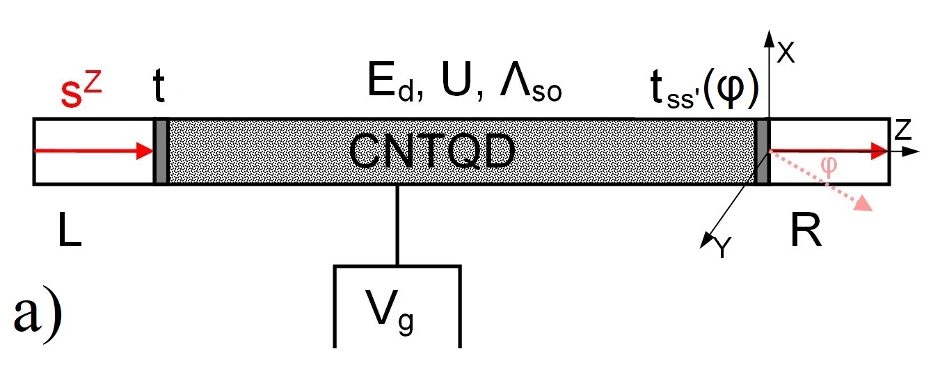
We discuss transport through carbon nanotube quantum dot coupled to the noncollinear spin polarized electrodes (Fig. 1a). CNTQD exhibits fourfold shell structure in the low energy spectrum. For short nanotubes with well separated energy levels it is enough to restrict at low temperatures to the single shell. The system is modelled by two-orbital Anderson model with equal intraorbital and interorbital interaction parameters U and the strength of spin-orbit coupling :
| (1) | |||
where , are the orbital and spin indexes. It is assumed that magnetization of the left electrode is oriented along the nanotube axis, whereas magnetization of the right electrode is tilted by angle (Fig.1a). is the creation operator in the left or right electrode , is hopping integral, () is the occupation number operator in CNTQD (lead), () denote energies of electrons in the lead (dot). For CNT with the wide bandgap, total spin-orbit contribution to energy (Zeeman-like and orbital-like) can be parametrized by a single effective SO parameter () McEuen . The tunneling elemets of the right electrode are given by , and . To analyze strongly correlation effects in the system we use finite slave boson mean field approach (SBMFA) of Kotliar and Ruckenstein Kotliar . Slave bosons , , , , and are introduced to describe empty, single , doubly, triple and fully-four occupied states respectively. Six bosons project onto states with double occupation of a given orbital , or onto the states with single occupation on each orbital .
The effective slave boson Hamiltonian (2) reads:
| (2) | |||
where is the pseudofermion occupation operator ( Kotliar ). and are the conservation and completness realtions. is the renormalization parameter of the coupling strength with left and right electrode. Couplings to electrodes are described by matrices and , where , for respectively, where and . The off-diagonal elements are with . is the rectangular density of states in the lead ( and denotes polarization of electrodes). Throughout this paper we use relative energy units chosen as the unit and we set . The spin and charge currents are given by (, , , ):
| (3) | |||
The currents are expressed by electrode-lead correlation functions, which can be found using the nonequilibrium Green functions. Finally they are given by integrals of the diagonal and off-diagonal elements of the transmission matrix , where are the retarded and advaced renornalized Green function matrix with diagonal and off-diagonal elements . Integrating the lesser Green functions, we can calculate the average spin components (, where , is the Fermi distribution function)Barnas . The differential conductance, tunnel magneto-resistance (TMR) and polarization of conductance are given by formulas: and (where . All the calculations were performed for and .
II Results and discussion
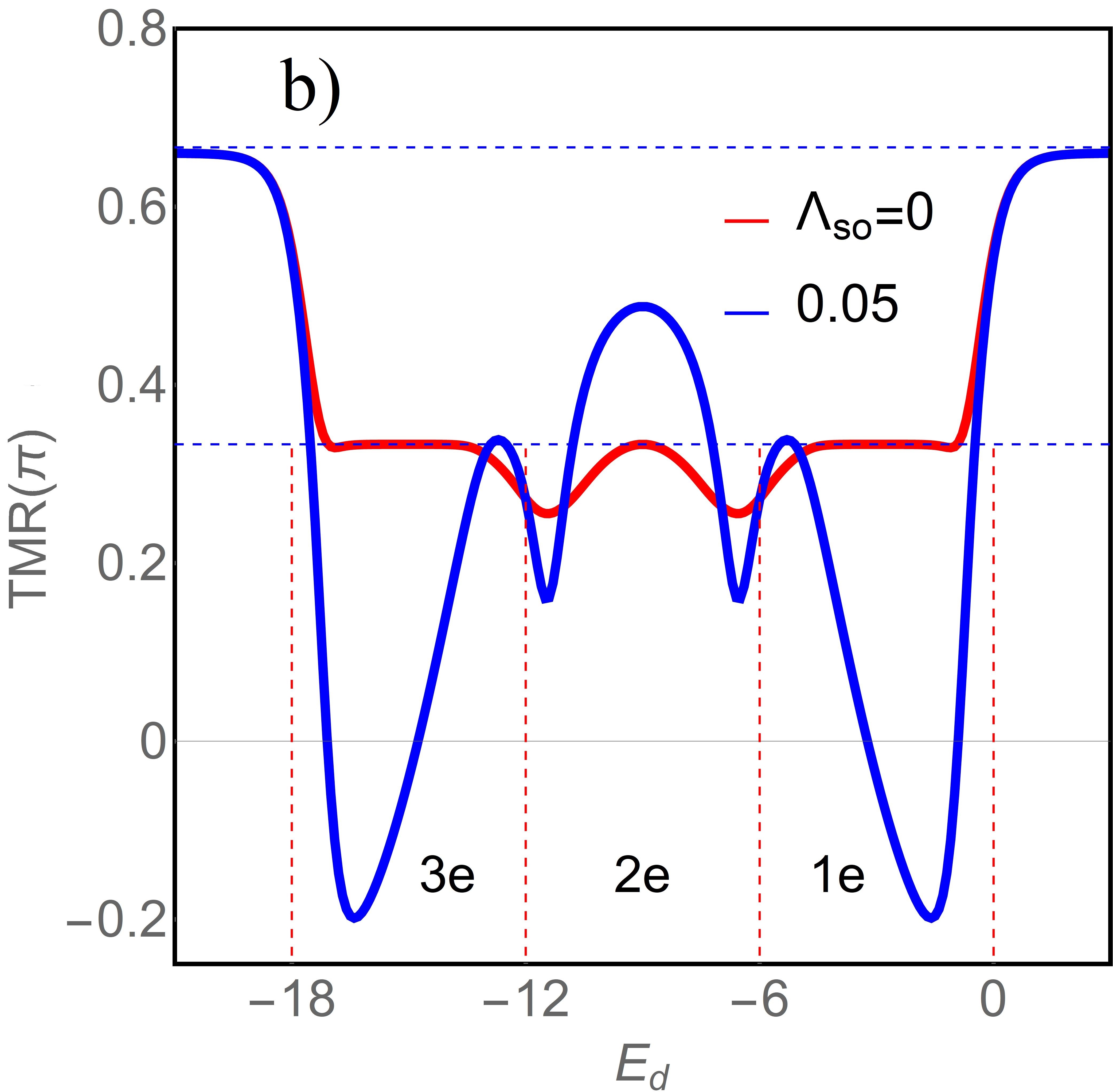
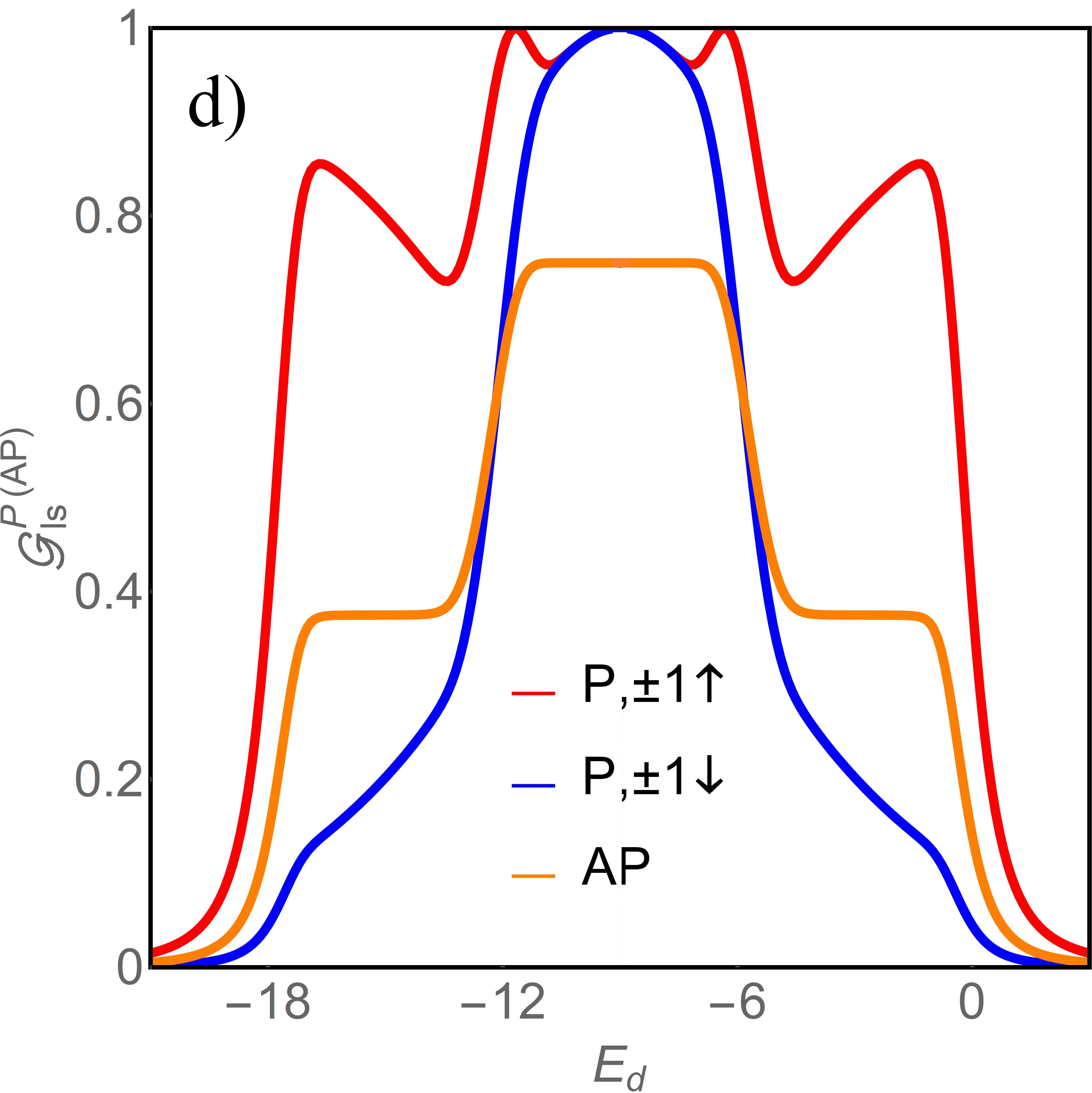
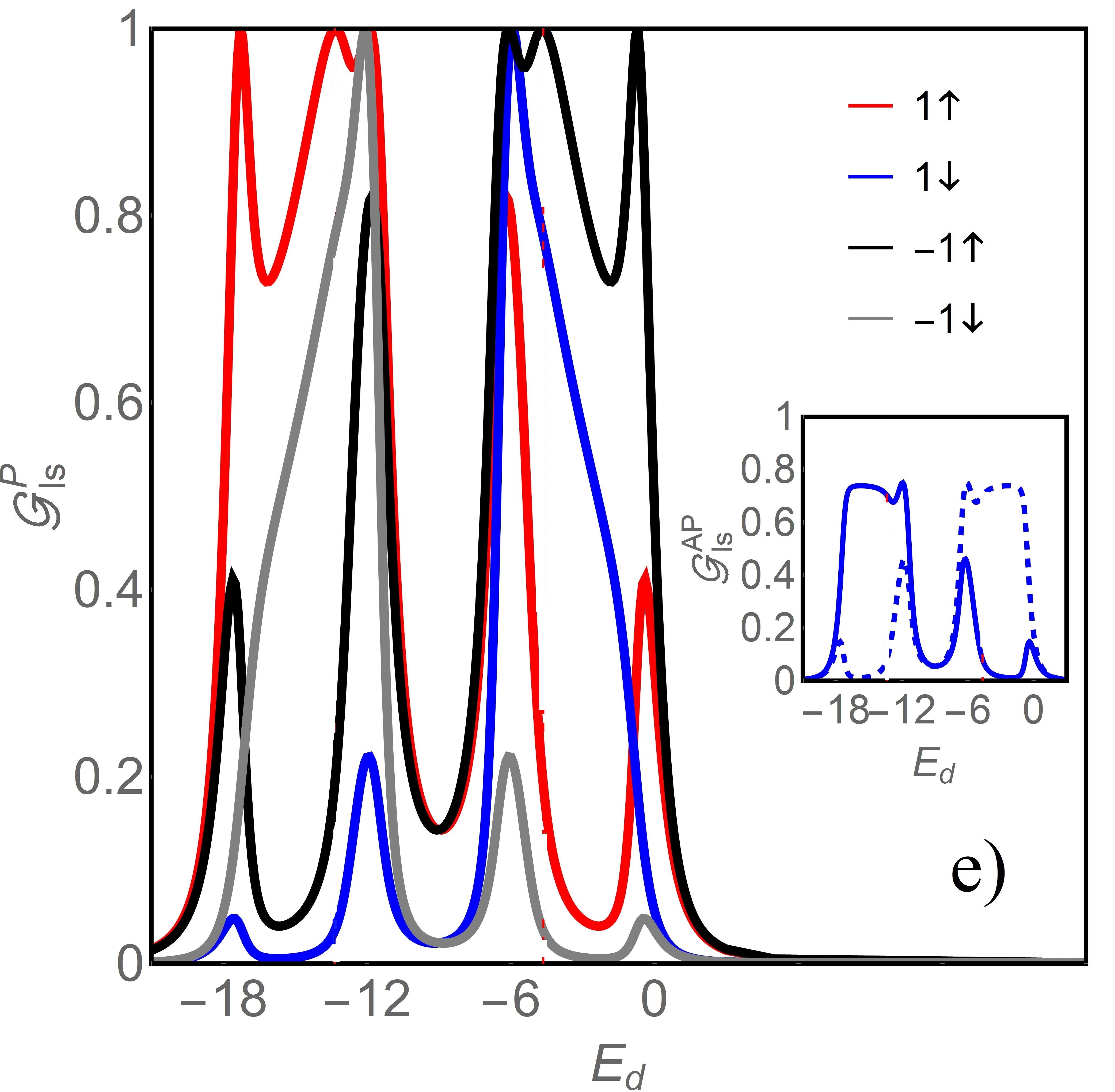
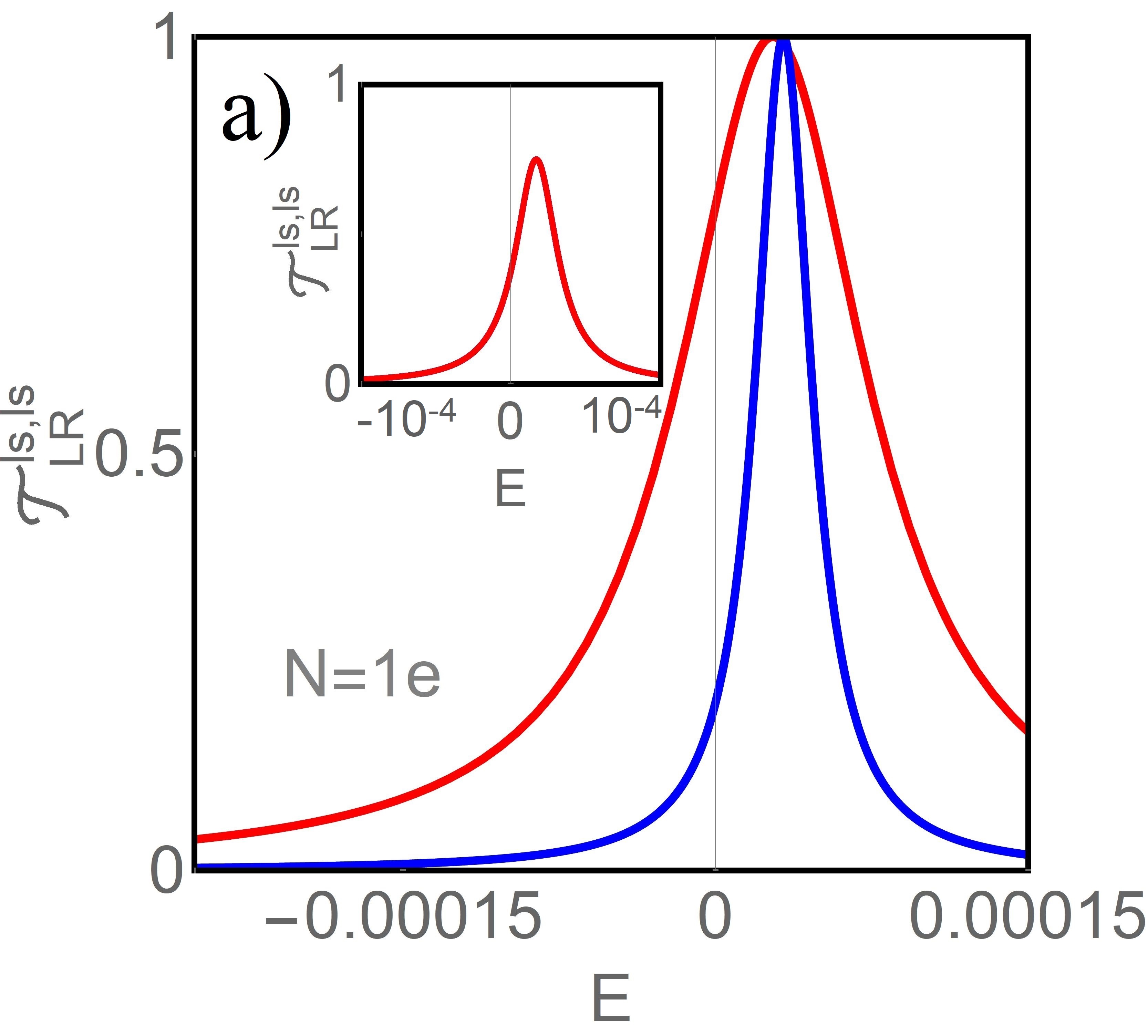
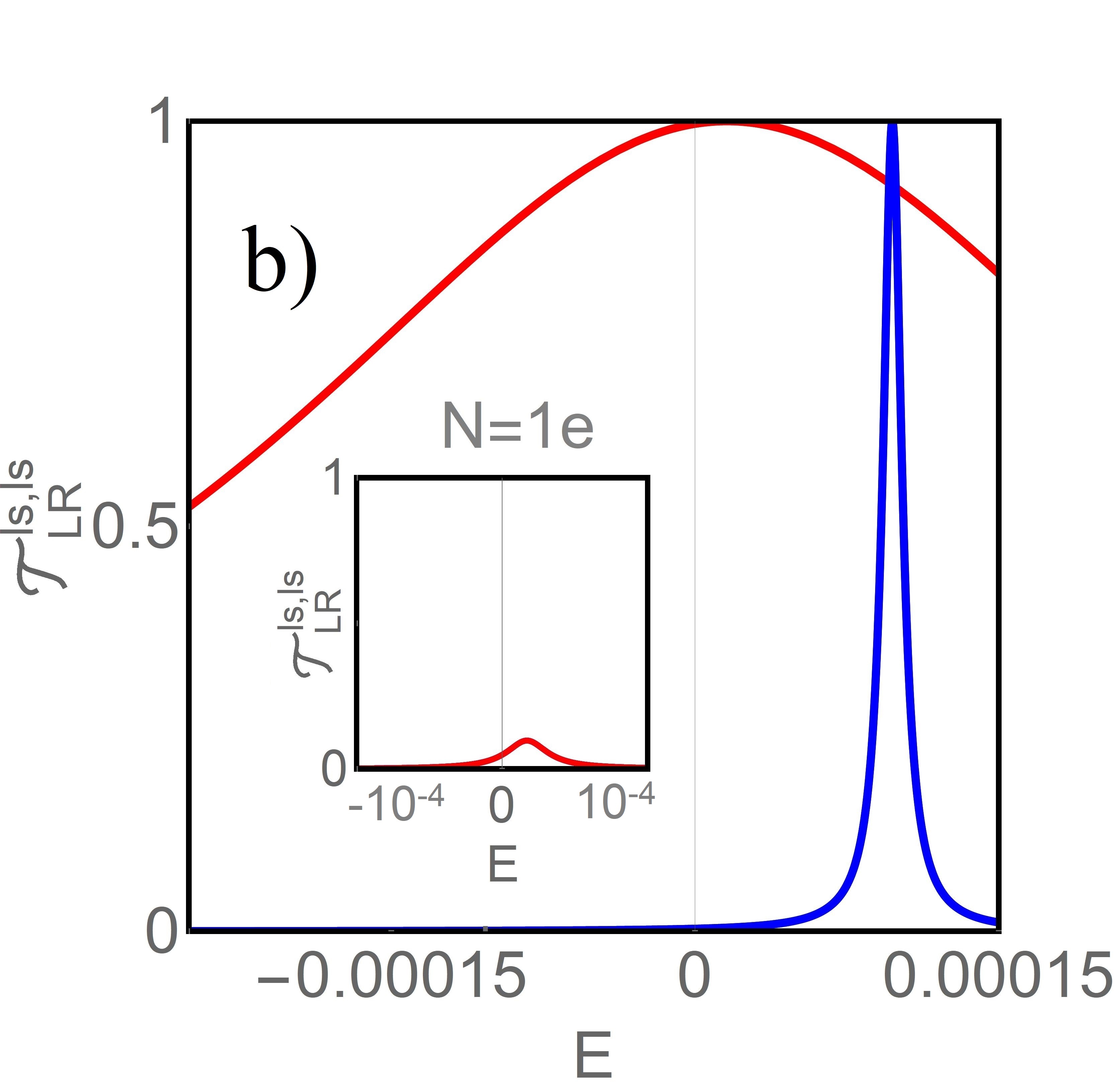
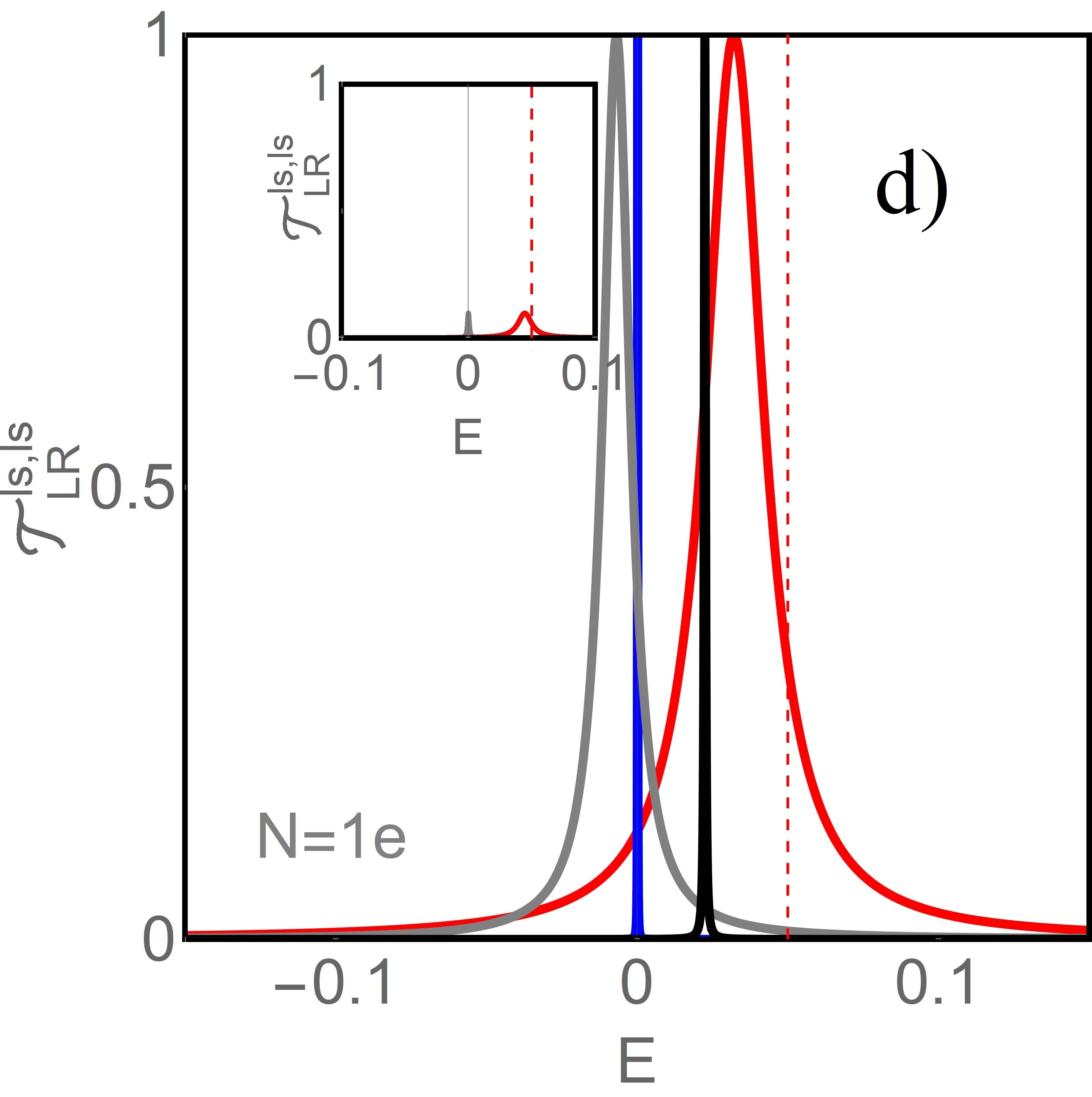
The major issue of spintronics is a control of transport by a change of relative orientations of magnetic moments of external leads. Fig. 1b shows the gate voltage dependence of tunnel magnetoresistance of CNT-QD and Figures 1d,e present the corresponding conductances for P and AP configurations. In collinear configuration of magnetizations of the leads the decisive role in linear TMR plays a competition of the central transmission peak (peak located closest to the Fermi level) of the diagonal transmission for parallel (P) configuration (Fig. 2a,b) and central peak for antiparallel (AP) orientation (insets of Fig. 2a,b). The majority peak is wider and located closer to the Fermi level. In AP configuration () only a single peak is visible with equal contributions of both spin orientations. As it is seen from comparison of Figs. 2a,b the disproportion between P and AP transmissions increases with increasing electrode polarization P, which means an increase in TMR. For AP transmission at the Fermi level disappears and transport is blocked (perfect spin valve effect). Without SO coupling () TMR reaches value only weakly dependent on gate voltage and determined by polarization of electrodes Moca and it increases up to Jullière limit when approaches fully occupied or empty regions of the dot. For clarification of gate voltage dependencies of TMR we present on Figs.1d, ecorresponding conductances for P and AP configurations. For AP conductance curve resembles dependence for , but with reduced plateau values for all occupations. This is a consequence of breaking of the left-right symmetry in individual spin channels. For P orientation differences between spin-resolved conductances result from violation of spin symmetry. For exchange splitting is small and vanishes at e-h symmetry point (inset of Fig. 3b). Transmissions for both spins locate close to and both spin resolved conductances reach almost unitary limits in the centre of valley. Outside this point they behave differently due to the different widths of transmissions. For transmission lines do not locate at and therefore the points of vanishing do not reflect in equality of conductances. For in P configuration conductances differ for different spin and orbital channels. Breaking of SU(4) symmetry reflects most strongly by suppression of conductances for , because in this region SU(4) Kondo temperature (, ) is lowest. In AP configuration there are only two different orbital resolved conductances, which are mirror reflections with respect to the e-h symmetry line. Independent on the sign of spin splitting conductance for parallel orientation of the magnetic moments of electrodes dominates over conductance for antiparallel orientation and TMR remains positive in the whole range of gate potential. This changes for non-zero SO coupling.
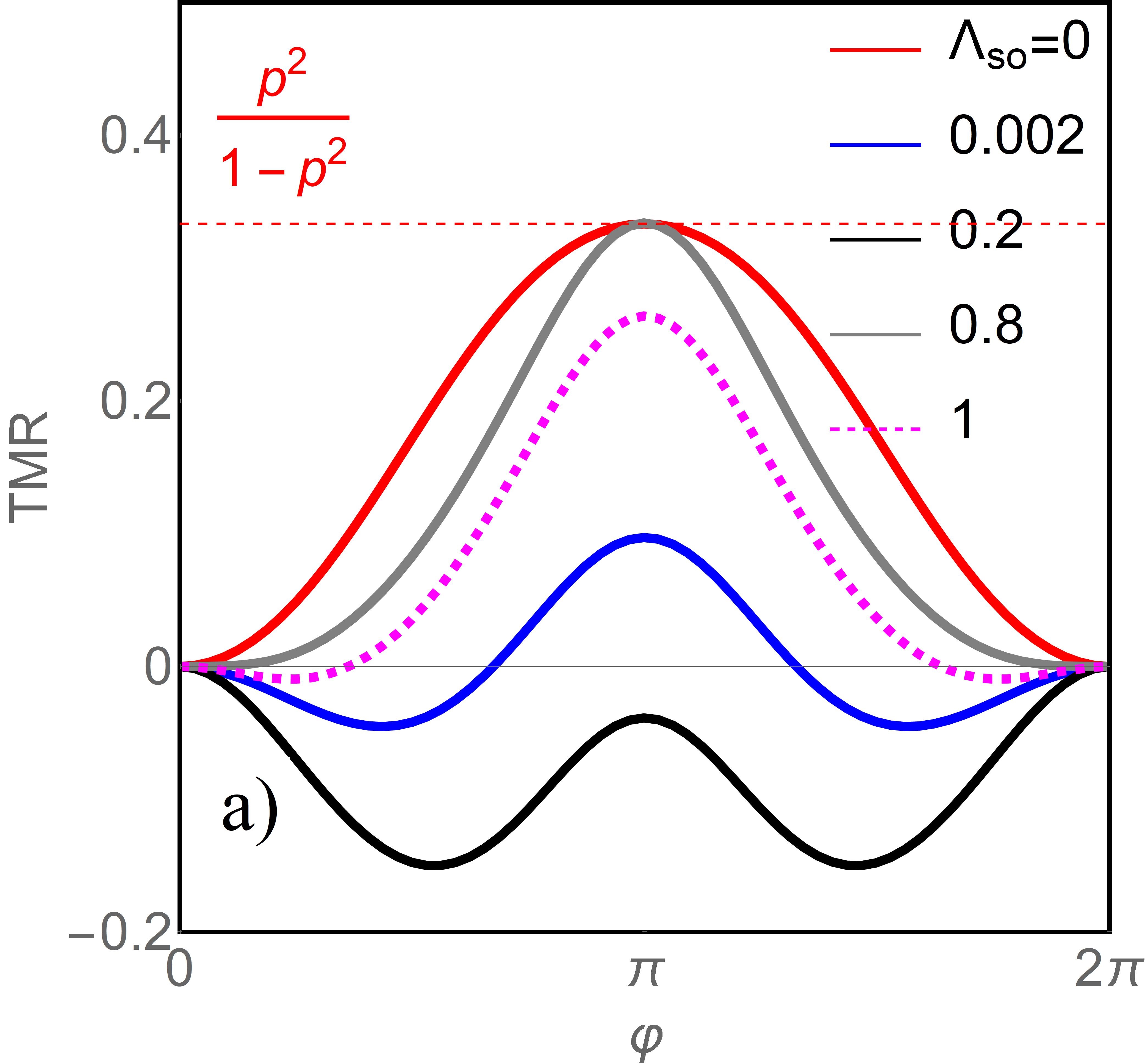
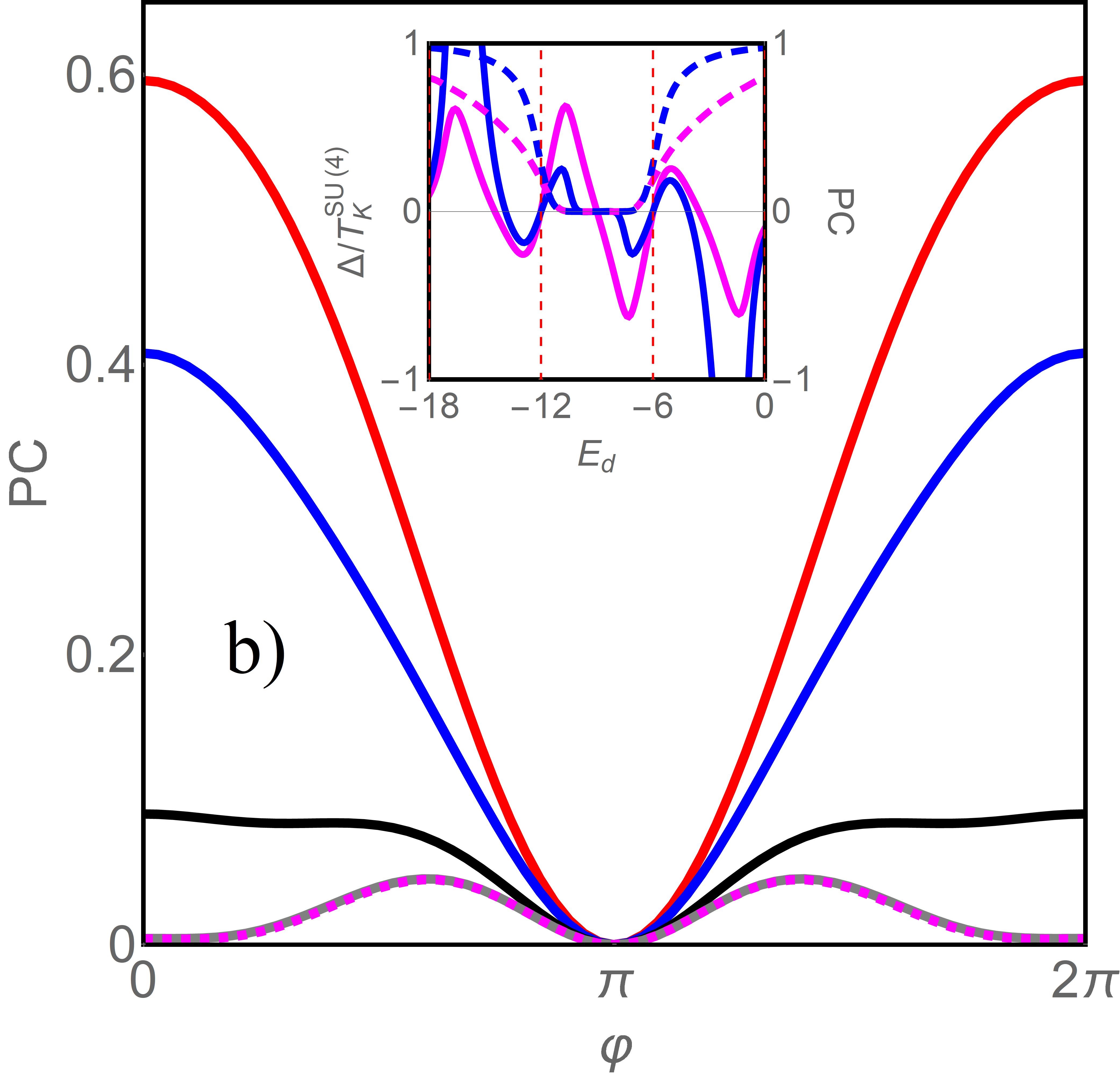
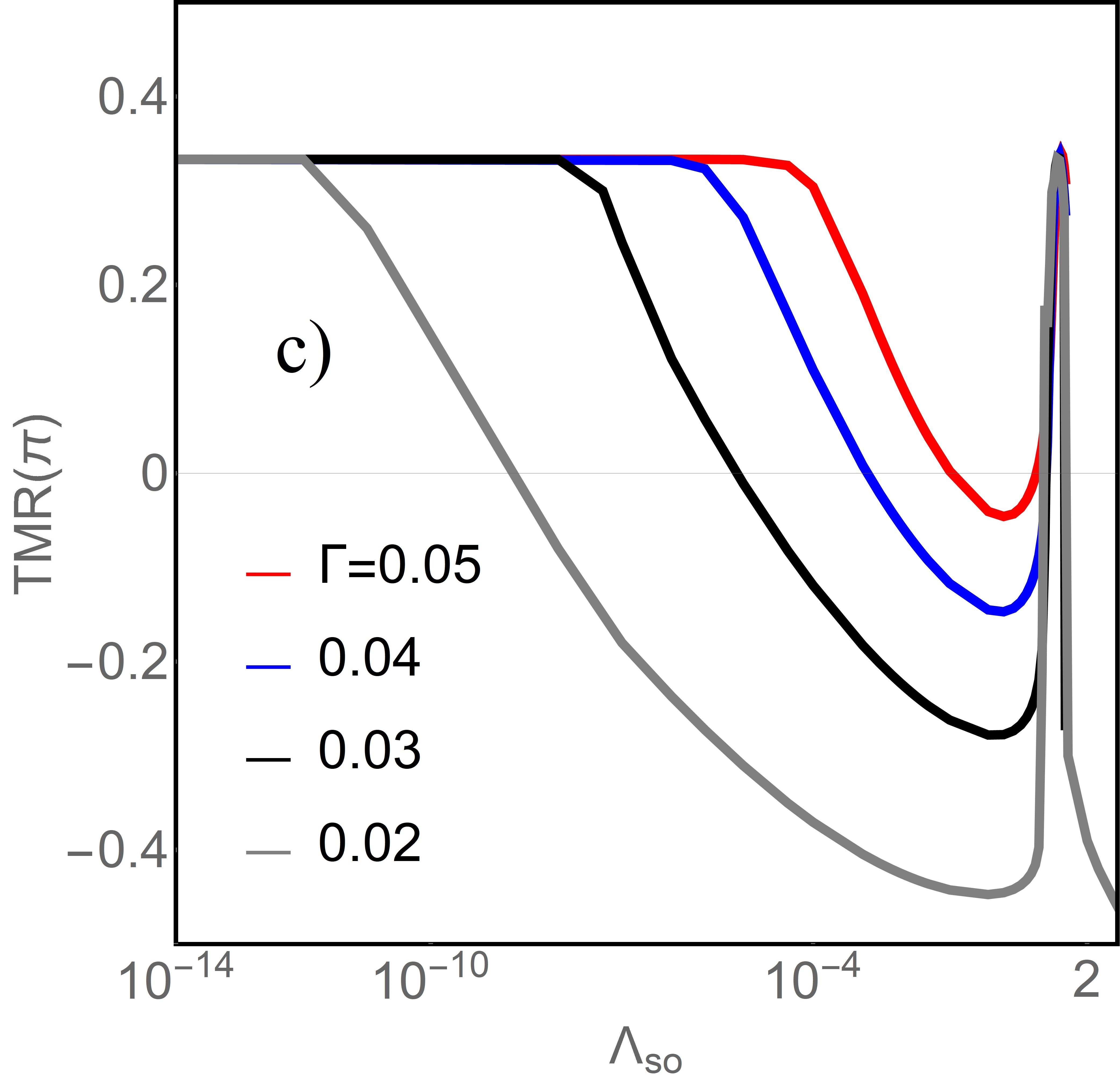
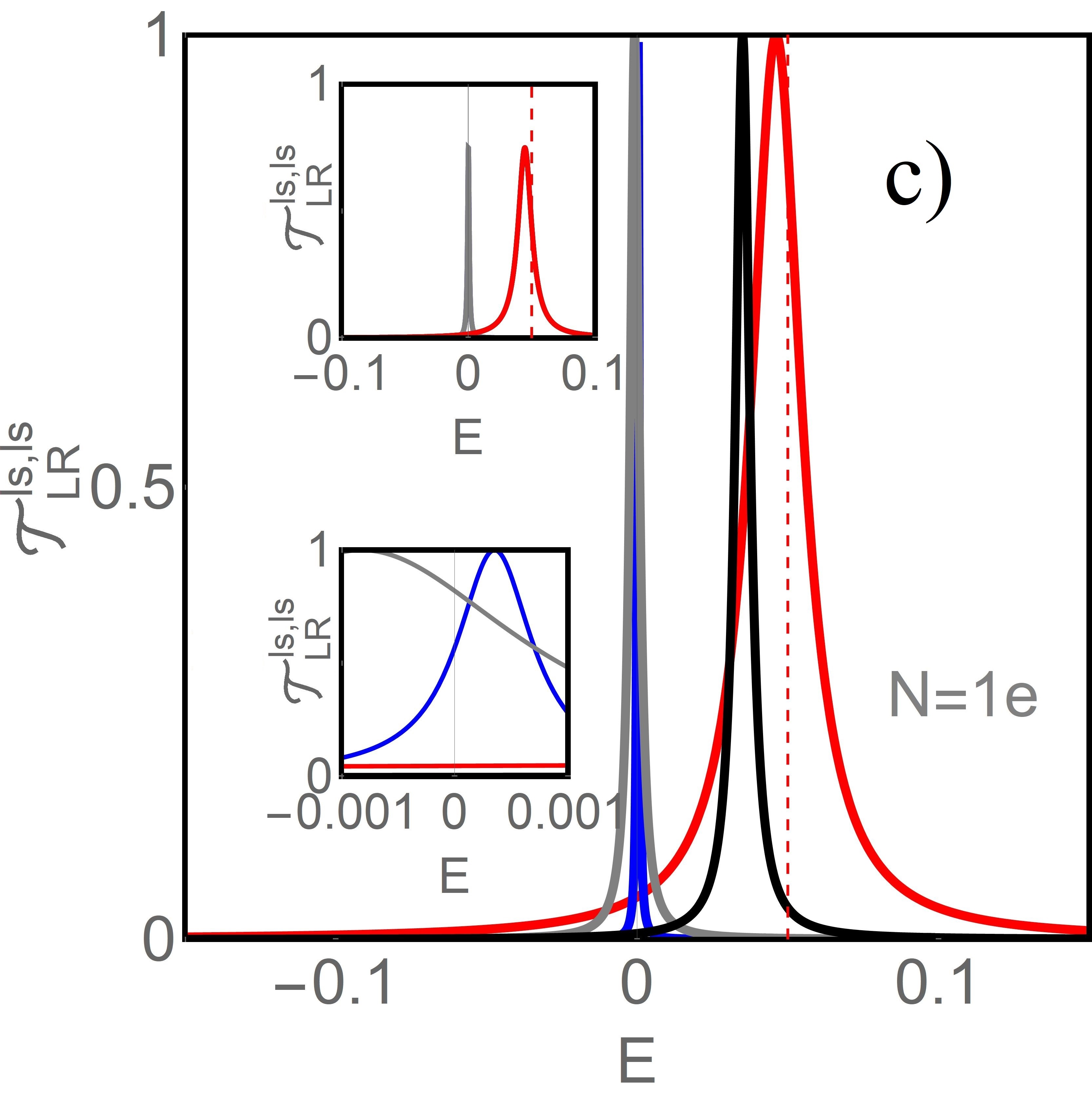
In transmission for P configuration in this case (Fig. 2c,d), additional satellite peak appears located approximately around in region or for and for . In the upper inset of Fig. 2d presenting transmission for AP orientation only satellite corresponding to the SO splitting is visible. The reconstruction of transmissions in P and AP configurations causes a suppression of TMR and for even the sign of magnetoresistance may change in some cases (inverse TMR). Fig. 1c illustrates what a strong effect on TMR has weakening of the coupling of the leads to the dot. As it is seen with the decrease of inverse TMR() appears at lower value of SOC. This is a consequence of narrowing of perturbed Kondo peaks and in consequence the spin-orbit induced splitting of transmission peaks occurs for smaller values of . Fig. 3a presents the angle dependence of TMR. When the directions of electrode magnetizations deviate from each other, TMR increases and reaches maximal value for . SO coupling decreases the amplitude of TMR oscillation and, as we already mentioned earlier, allows for its negative values. Inverse TMR is observed already for very small values of SOC () and maximal value reaches for for noncollinear configuration ( and ). Fig. 3b shows the oscillating, decreasing with the increase of , angle dependence of polarization of current with maximum for P configuration, what is a direct consequence of highest transmission for spin up channel for this configuration (Fig.2). Despite the fact that exchange field changes sign when moving form region into PC remains positive for all gate voltages (inset of Fig. 3b). Kondo temperature changes with gate voltage and it ranges from to .
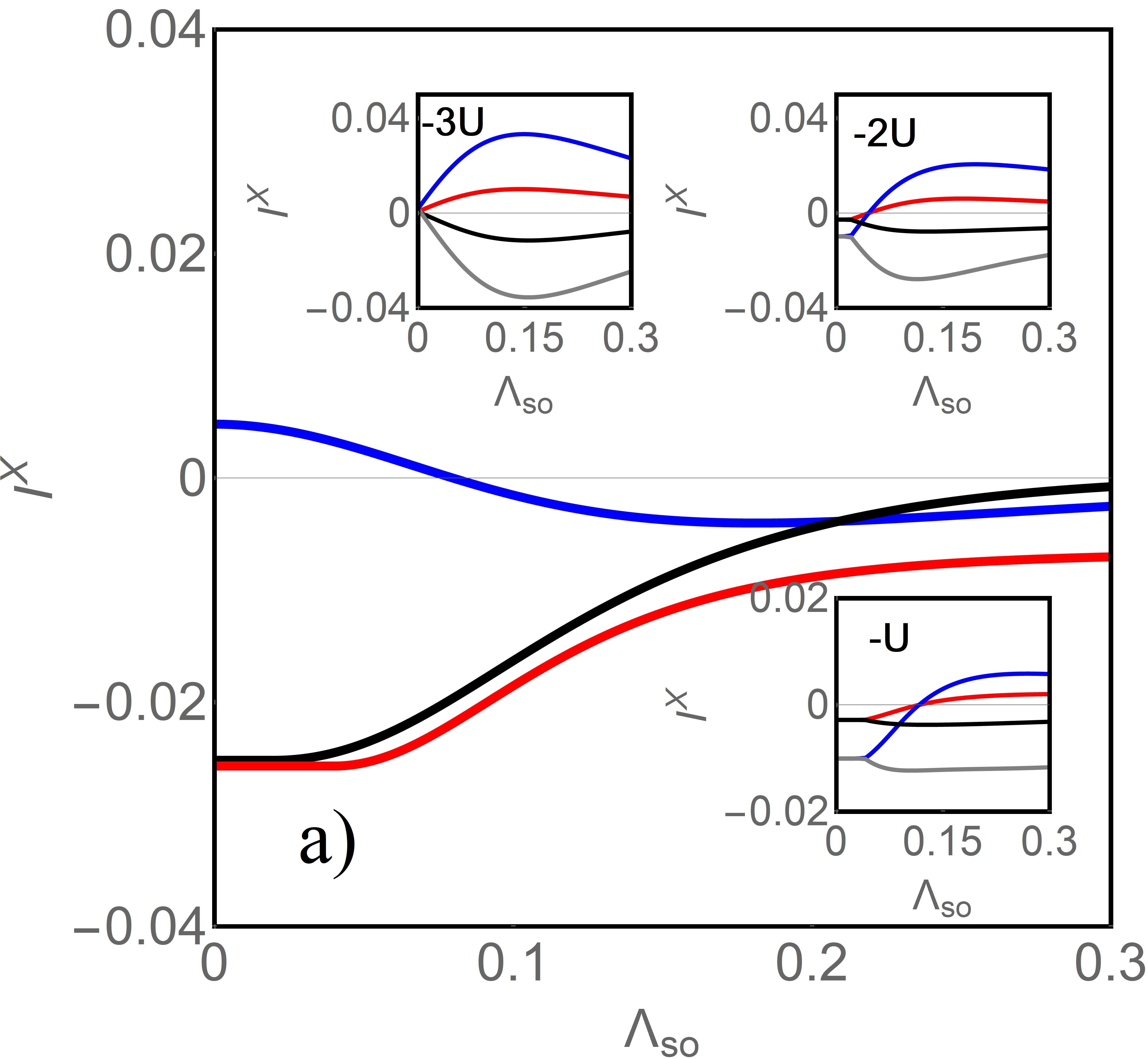
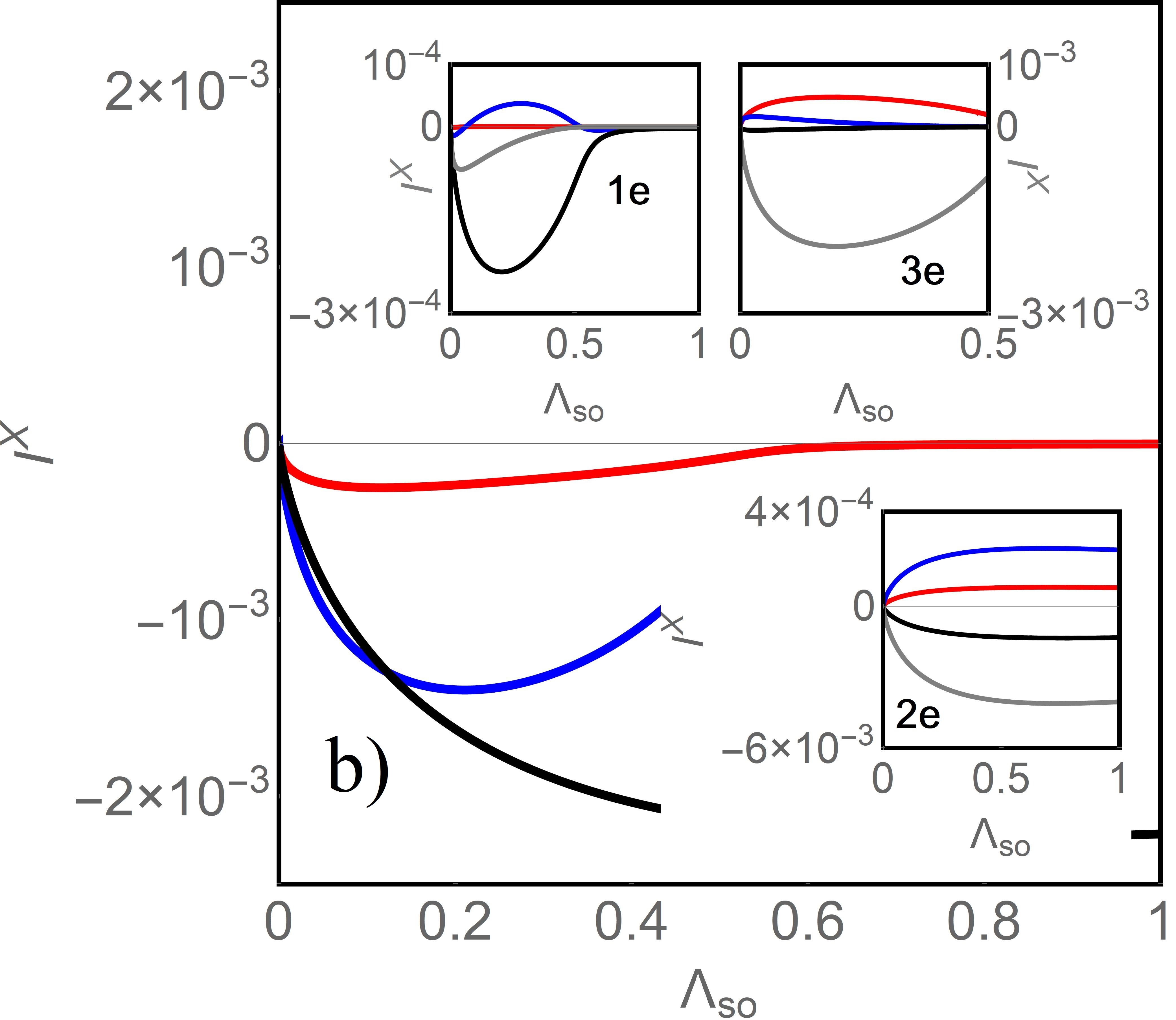
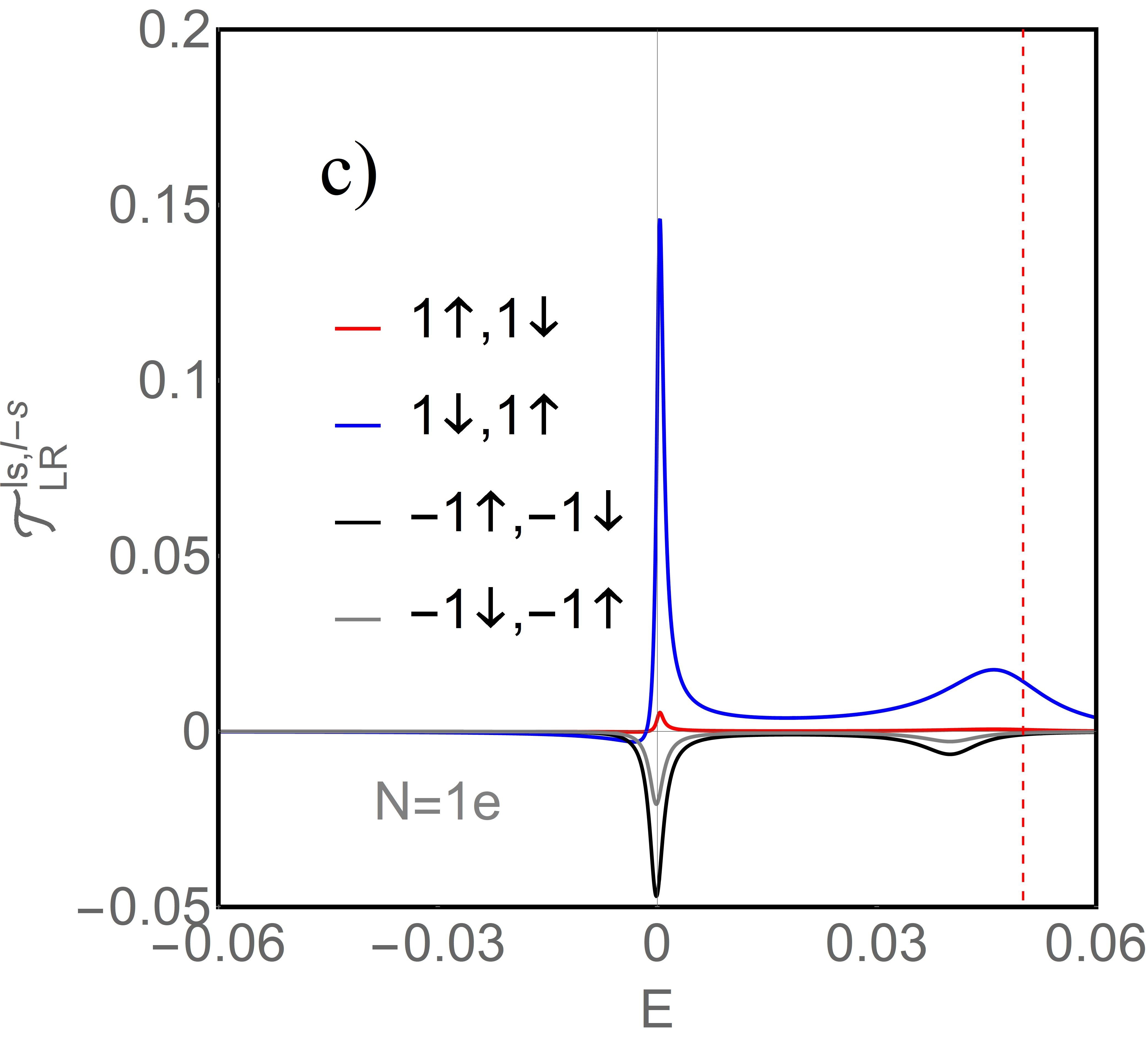
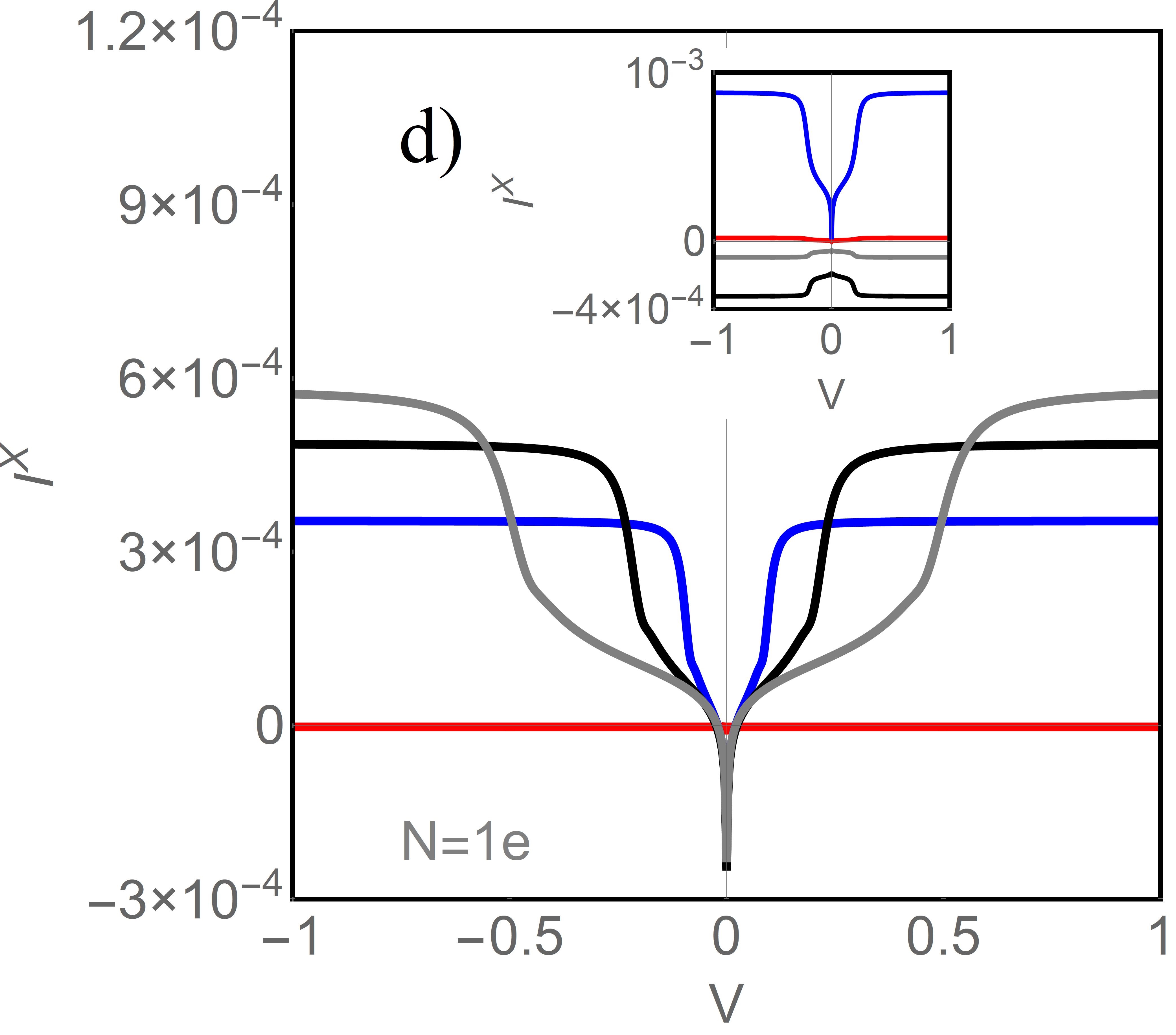
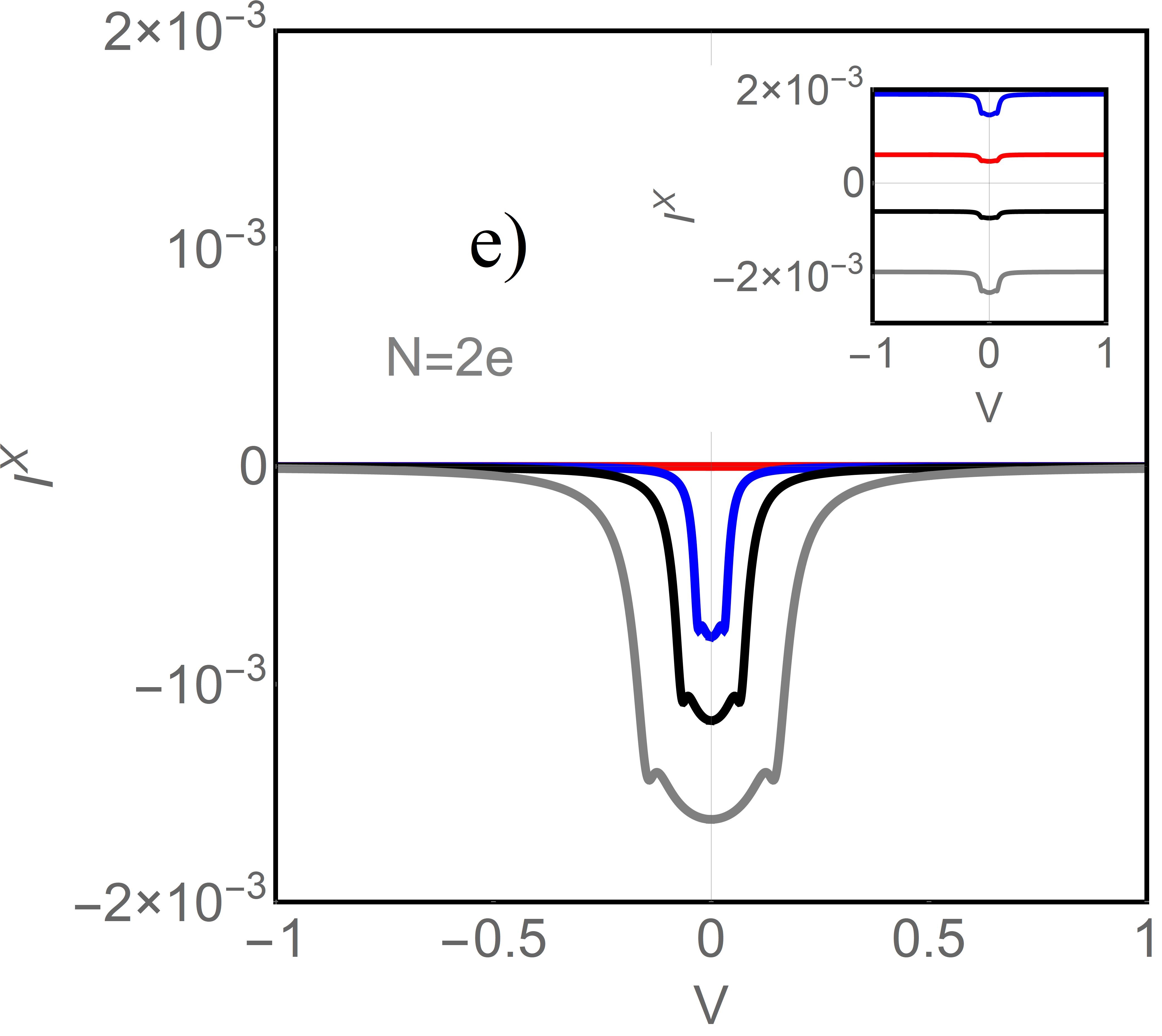
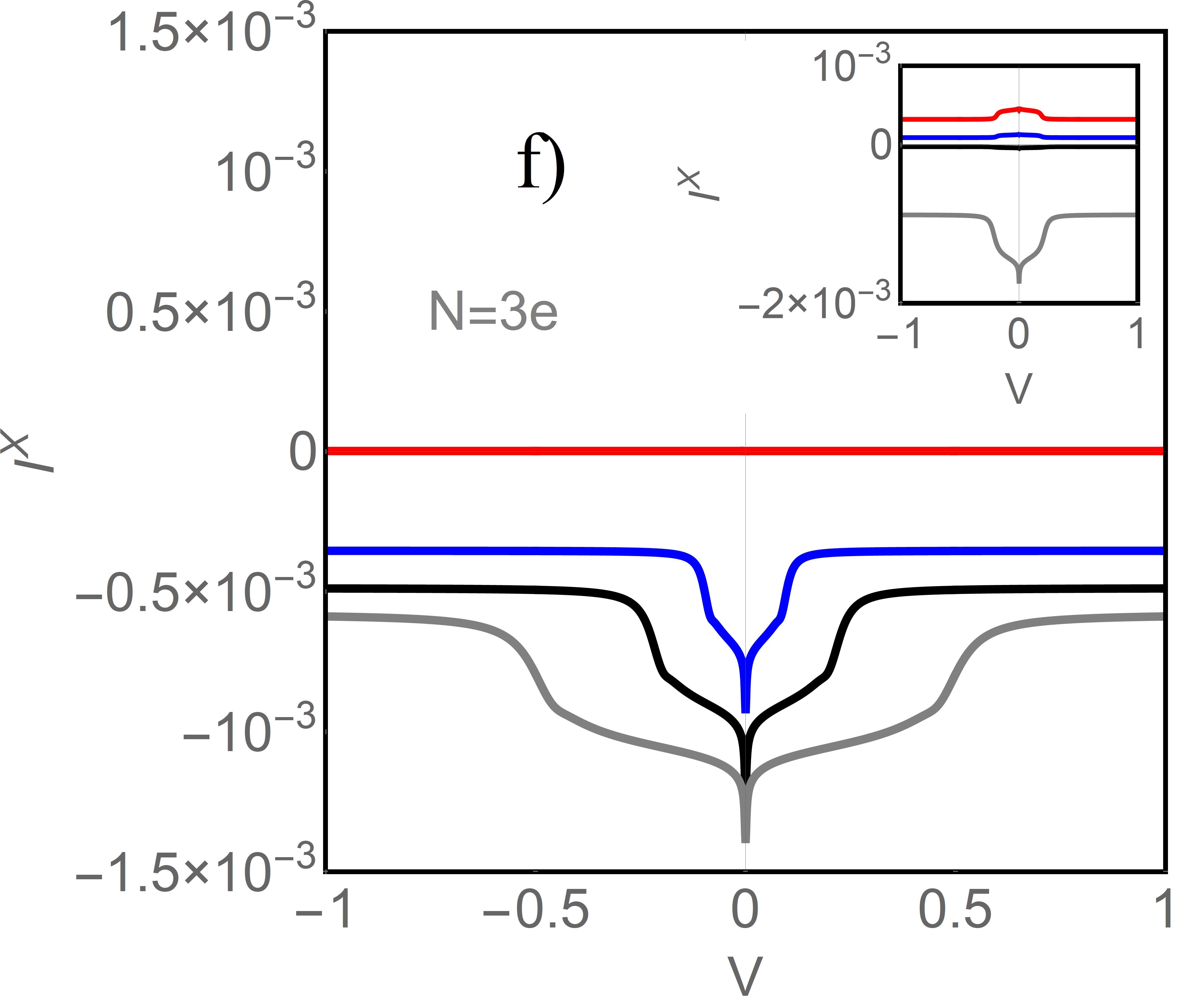
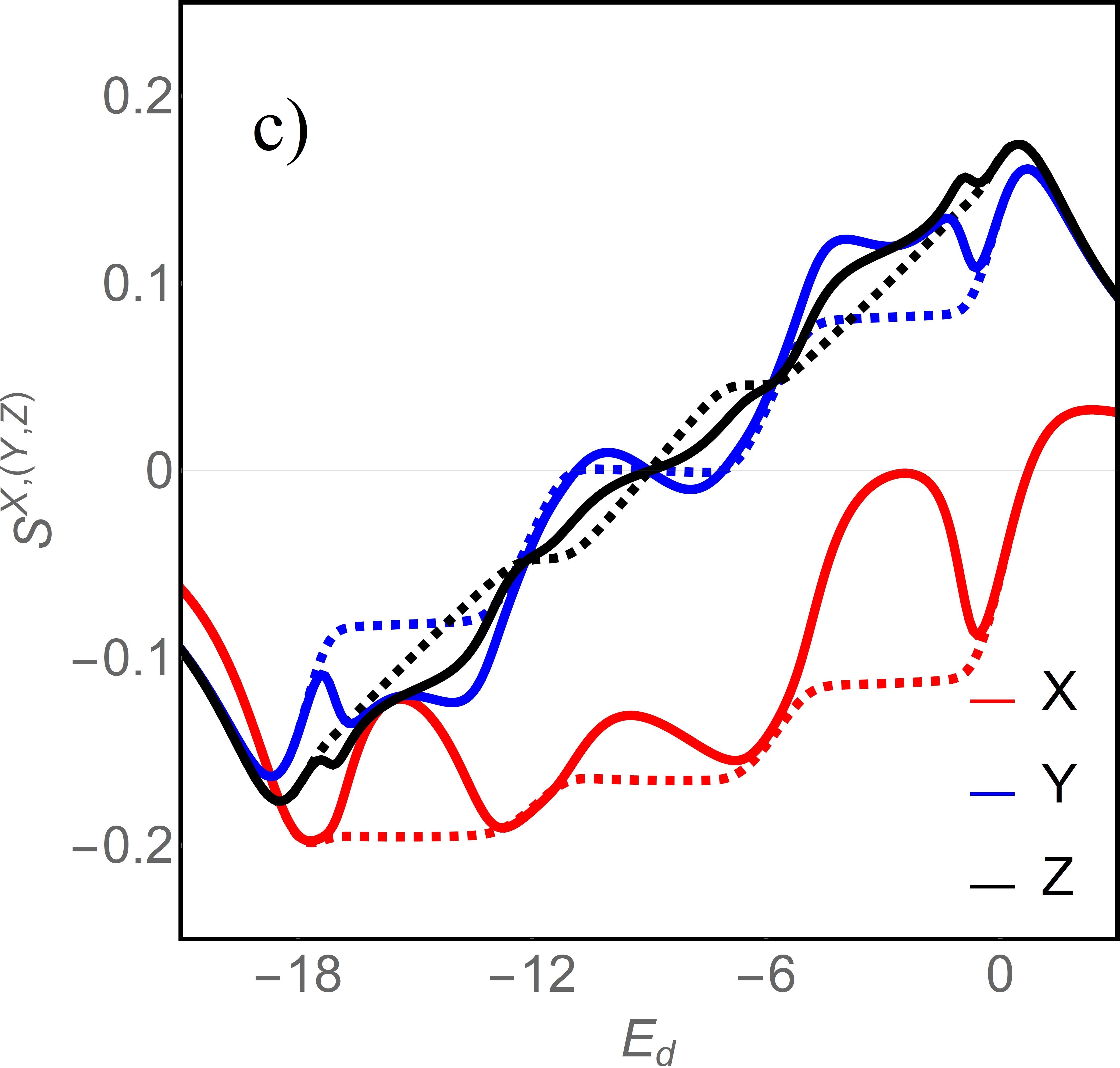
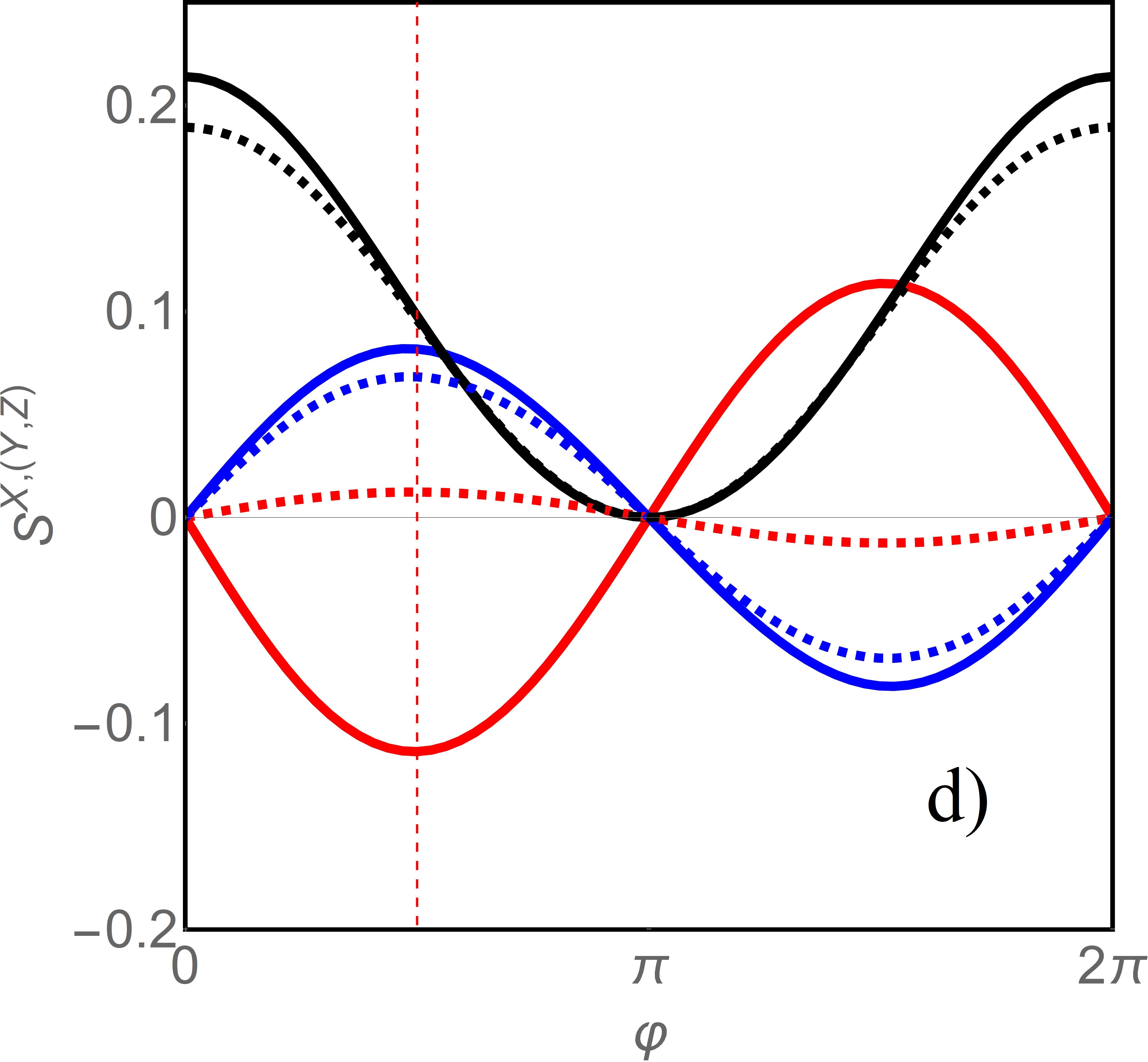
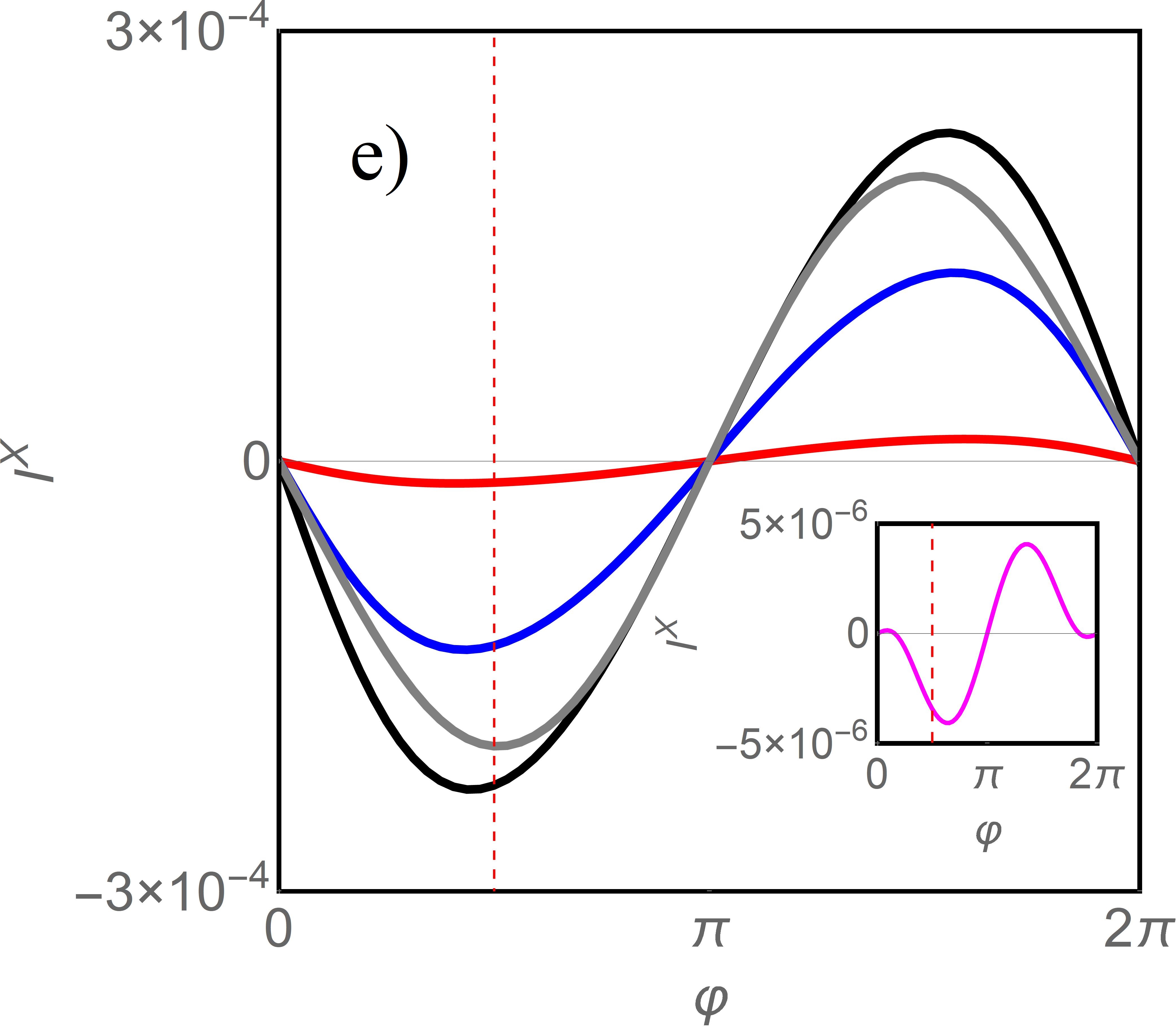
Coupling of CNTQD to polarized electrodes induces spin accumulation. The average values of spin components plotted as a functions of gate voltage for and for nonvanishing SO coupling are shown on Fig. 3c. Due to exchange field induced by polarized electrodes the dot magnetic moment is suppressed, but not quenched and local extrema occur at the boundaries of Coulomb blockades. The change of the sign of transverse spin components when crossing electron-hole symmetry point is the consequence of reversal of the effective exchange field. The angle dependencies of average spin components are shown on Fig. 3d. vanishes for antiparallel configuration (), whereas transverse components vanish for and . SO coupling diminishes the oscillation amplitude. Recently there has been an increasing interest in generation of pure spin currents without an accompanying charge current. Fig. 3e presents the angle dependencies of equilibrium (zero bias) transverse component of spin current (ESC). When magnetic moments of electrodes are deviating from the parallel orientation the transverse components of the exchange field appear. For the geometry considered it is component of the effective field () and spin torque pointing in direction exerts on electrons flowing through the dot ( in the global Z axis). Torque is oriented in the opposite directions for right and left moving electrons. In consequence, the charge flow in opposite directions is associated with opposite x components of the spin. Fig. 4 concerns AP configuration. Fig. 4a presents dependencies of ESC on SO coupling strength at the borders of Coulomb blockades and Fig. 4b the same dependencies for the regions of broken Kondo states for occupations . In the former case absolute values of decrease with the increase of SO coupling, whereas for the latter nonmonotonic dependencies are observed with predominantly increasing tendencies of for small values of . Although the behavior of ESC is determined by a subtle interplay of integrated to the Fermi level off-diagonal in spin space transmissions, the increasing tendency in Kondo regime reflects the general property of increase of currents due to the increase of electrode-dot coupling with SO induced weakening of Kondo correlations. Fig. 4c shows examples of zero-bias partial off-diagonal transmissions for . dominates at and so does the corresponding integral up to determining spin-flip contribution to . Its largest and negative contribution is shown in the left upper inset of Fig. 4b. Similar partial, orbital resolved spin-flip equilibrium spin currents for selected gate voltages are presented on the rest of insets of Figs. 4a,b. Figs. 4 d,e,f present bias voltage dependencies of spin current for different occupation regimes. Independent on the value of , the spin current remains negative for and , whereas for it changes sign at small voltages. For the detailed explanation of this observation the picture of the evolution of spin-flip transmissions with voltage should be recalled, but even from the insight into the zero-bias transmissions (Fig. 4 and its inset) it is seen that by increasing the transport window the positive contribution starts to dominate in over the negative.
Summarizing, we have investigated the effect of spin-orbit coupling and Kondo correlations on spin currents and tunnel magnetoresistance in carbon nanotube quantum dot comparing also some calculations with the results for the boundaries between the Coulomb valleys. Discussion of SO effects and noncollinearity of polarizations is important because the energy of SO coupling is comparable with the energy scale of Kondo effect and deviations of polarizations introduce real spin-flip processes. In consequence the many body resonances are formed due to the interplay between Kondo-like effective spin-orbital flips and real spin-orbit transitions. Apart from the current with spin component parallel to the global quantization axis, noncollinearity of polarizations induces also transverse components (spin-flip currents), which do not vanish even in equilibrium. ESC comes from the exchange coupling between the magnetic moments of ferromagnetic electrodes and its direction is determined by the vector product of these magnetizations. The spin currents scale with coupling strengths to the leads and as such are much weaker in the Kondo range than in Coulomb charge fluctuation regions. Spin-orbit coupling weakens TMR, but due to this interaction the inverse TMR effect may occur.
References
- (1) I. Žutić, J. Fabian, S. Das Sarma, Rev. Mod. Phys. 76, 323-410 (2004).
- (2) D. Loss, P. DiVincenzo, Phys. Rev. A 57, 120 (1998).
- (3) D. D. Awschalom, D. Loss, N. Samarth, Semiconductor Spintronics and Quantum Computation (Springer-Verlag Berlin Heidelberg, 2002).
- (4) A.Cottet, T.Kontos, S. Sahoo, H.T. Man, M.-S. Choi, W. Belzig, C. Bruder, A. F. Morpugo, C. Schonenberger, Semicond. Sci. Technol. 21, 78 (2006).
- (5) W. Liang, M. Bockrath, H. Park, Semicond. Phys. Rev. Lett. 88, 126801 (2002).
- (6) F. Kuemmeth, S. Ilani, D. C. Ralph, P.L. McEuen, Nature (London) 453, 448 (2008).
- (7) G. Kotliar, A.E. Ruckenstein, Phys. Rev. Lett. 57, 1362 (1986).
- (8) W. Rudziński, R. Świrkowicz, J. Barnaś, M. Wilczyński, J. Magn. Magn. Mat. 294, 1-9 (2007).
- (9) I. Weymann, R. Chirla, P. Trocha, C. P. Moca, Phys. Rev. B 87, 085404 (2018).