Secondary slip of screw dislocations in zirconium
Abstract
Plasticity in hexagonal close-packed zirconium is controlled by screw dislocations which easily glide in the prismatic planes where they are dissociated. At high enough temperatures, these dislocations can deviate out of the prism planes to also glide in the first order pyramidal and basal planes. To get a better understanding of these secondary slip systems, we have performed molecular dynamics (MD) simulations of a screw dislocation gliding in a basal plane. The gliding dislocation remains dissociated in the prism plane where it performs a random motion and occasionally cross-slips out of its habit plane by the nucleation and propagation of a kink-pair. Deviation planes are always pyramidal, with an equal probability to cross-slip in the two pyramidal planes on both sides of the basal plane, thus leading to basal slip on average. Basal slip appears therefore as a combination of prismatic and pyramidal slip in the high stress regime explored in MD simulations. This is confirmed by nudged elastic band (NEB) calculations. But NEB calculations also reveal a change of glide mechanism for a decreasing applied stress. At low stress, kinks do not lie anymore in the pyramidal planes. They are now spread in the basal planes, thus fully compatible with a motion of the screw dislocation confined to the basal plane as seen in experiments. Basal slip, which is in competition with pyramidal slip, appears therefore favoured at low stress in pure zirconium.
keywords:
Dislocation, Plasticity, Zirconium, Basal slip, Pyramidal slip1 Introduction
Plasticity in hexagonal close-packed (hcp) zirconium mainly processes by glide of dislocations with Burgers vector in the prismatic \hkl10-10 planes. This principal slip system observed in hcp Zr is well rationalised by ab initio calculations which show that \hkl¡a¿ screw dislocations are dissociated in the prismatic planes where they can easily glide without experiencing any relevant lattice friction [1, 2]. But at high enough temperatures, these dislocations can deviate out of the prism planes to also glide in the basal \hkl(0001) planes, and more rarely in the pyramidal \hkl10-11 planes.
Numerous transmission electron microscopy observations [3, 4, 5, 6, 7] have provided evidences of basal slip at various temperatures. Post-mortem TEM [3, 6] show the presence of \hkl¡a¿ dislocations lying in the basal planes at room temperature after sufficient plastic strain, and Akhtar and Techtsoonian [4] observed that basal slip is already active at 78 K when the strain is high enough. At much higher temperatures, above 850 K, Akhtar [5] showed that basal slip was the only activated secondary slip system in addition to easy prismatic slip, with the relative ease of basal slip increasing with temperature. Slip traces analysis also confirm the activation of basal slip at room temperature [8, 9, 10, 11] and above up to 623 K [12]. Finally, basal slip could be observed in situ by TEM in pure Zr at and above room temperature [13, 7]. In agreement with these observations, in situ compression experiments during neutron diffraction experiments [14] on polycrystals with various textures suggest basal slip activity operating at a higher applied stress than prismatic slip at room temperature, but at a similar applied stress above 373 K.
In situ TEM observations [7] show that basal slip is controlled by the viscous glide of straight screw dislocations, an indication of a Peierls mechanism with dislocation moving by the nucleation and propagation of kink pairs. This agrees with ab initio calculations which show that a dissociation of the screw dislocation in the basal plane is unstable [1] and that screw dislocations remain dissociated in the prismatic plane while gliding in the basal plane, thus leading to a high energy barrier opposing basal glide [15].
Although pyramidal glide of dislocations is another possible secondary slip system in hcp Zr, less experimental observations reported activity of this slip system. Tenckhoff [16] mentioned that pyramidal slip occurs in regions of high stress concentration, such as grain boundaries, and Caillard et al. [7] underlined that pyramidal slip necessitates especially favourable stress conditions compared to basal slip. Direct evidences of pyramidal slip have been indeed mainly detected in zirconium alloys and at high enough temperature. Post-mortem TEM observations in a M5 alloy [17] reveal glide of \hkl¡a¿ dislocations in pyramidal \hkl10-11 planes activated through cross-slip from prismatic principal slip systems after creep at 673 K. But in situ TEM straining experiments performed in the same alloy between 523 and 723 K indicate that cross-slip proceeds mainly in the basal plane [13, 7]. On the other hand, Drouet et al. [18] observed during in situ TEM straining experiments glide of \hkl¡a¿ dislocations in pyramidal planes in recrystallised Zircaloy-4 between 723 and 773 K and reported that basal slip was not activated. Pyramidal slip was also reported by Gaumé et al. [19] still in Zircaloy-4, both at room temperature and between 623 and 723 K either in unirradiated or irradiated samples.
Basal and pyramidal slip appear therefore as two possible secondary slip systems for \hkl¡a¿ dislocations in zirconium, with basal slip being easier to activate, at least in pure zirconium. Ab initio calculations [15] concluded that these two slip systems are indeed intertwined as the same energy barrier is obtained for a straight screw dislocation gliding either in a basal or a pyramidal plane. The dislocation, which remains dissociated in a prismatic plane, glides in both cases through the conservative motion of the stacking fault ribbon perpendicular to the dissociation plane, without any constriction of the dissociated core. Most importantly, these ab initio calculations have shown that basal glide is a combination of prismatic and pyramidal glide. Basal slip should therefore be composite. But this is not compatible with experimental results described above, in particular the observation of slip traces fully resolved in the basal planes [11, 7]. As underlined by Caillard et al. [7], glide of \hkl¡a¿ dislocations in basal planes should be an elementary slip system in zirconium. It it the purpose of this article to look how the mechanism given by ab initio calculations for secondary slip systems of \hkl¡a¿ dislocations in zirconium, in particular basal glide, can be reconciled with the various experimental observations. As it appears necessary to go beyond the motion of an infinite straight screw dislocation, we use molecular dynamics simulations to study glide of a screw dislocation in zirconium, thus allowing for localised thermally activated events like nucleation of kink pairs. The obtained glide mechanism is then analysed in more details and in a larger stress range with energy barrier calculations. Finally, we discuss how results of atomic simulations match with experiments.
2 Molecular dynamics simulations
2.1 Methods
All atomic simulations are carried out with the embedded atom method (EAM) potential developed by Mendelev and Ackland (potential #3) [20]. This potential predicts the correct ground state of the \hkl¡a¿ screw dislocation [1] with a core dissociated in the prismatic plane in two partial dislocations, in agreement with ab initio calculations [1, 15, 2]. The infinite stable stacking fault found in the prismatic plane with this potential has a slightly different atomic structure, in particular a different fault vector, than the ab initio one, but this does not result then in any significant dissimilarity for the relaxed configuration of the dislocation core [1]. A metastable configuration where the screw dislocation dissociates in two Shockley partials in the basal plane is also obtained with this potential, while ab initio calculations show that such a configuration should be unstable [1]. But, as this spurious configuration has a much higher energy than the prismatic ground state ( meV Å-1), it takes no part during dislocation motion. This potential actually leads to the same mechanism for basal glide of a straight screw dislocation as ab initio calculations: basal glide operates through displacement of the prismatic stacking fault perpendicular to its habit plane leading to a metastable configuration, halfway through the migration, where the dislocation is partially spread in a pyramidal plane [15, 21]. During this elementary slip event, the dislocation trajectory can be decomposed into three steps: the dislocation glides first in a prismatic plane, then in the pyramidal plane and finally again in a prismatic plane, with an energy barrier opposing dislocation motion only in the pyramidal part of the trajectory.
The simulation box is oriented with axis along the dislocation direction (), along the glide direction in the basal plane (), and orthogonal to the basal glide plane (). It is periodic along and directions, with controlled surfaces along the direction. The corresponding sizes are , and Å, leading to a cell containing 1.2 million atoms. As the screw dislocation can easily glide in its prismatic plane in the direction, large size is needed to allow thermal fluctuations of the dislocation position in the prismatic plane while preventing it to get out of the slab. The dislocation length is large enough to allow for the nucleation of kink pairs in the considered stress range.
The screw dislocation is introduced in the middle of the simulation box using the displacement field predicted by elasticity theory. Upon relaxation, the dislocation spontaneously dissociates in two partials in the prismatic plane. The temperature is initialised to the target temperature. After an initial thermalisation stage, molecular dynamics (MD) simulations are performed with a 2 fs time step in the ensemble without any thermostat: despite the work of the applied stress, the cell is large enough for the temperature increase to be negligible during the whole dynamics. We use stress controlled simulations [22]: an average force is imposed on the atoms in the outer layers close to the two -surfaces to apply a shear stress . This shear stress leads to a Peach-Koehler force on the dislocation resolved in the -direction, thus promoting basal glide, without any resolved shear stress in the prismatic plane to prevent easy glide in this plane. All simulations are carried out with Lammps [23] for applied stresses in the range 600 - 1200 MPa and for temperatures in the range 300 - 900 K.
2.2 Dislocation velocity

All MD simulations lead to the same glide mechanism, whatever the applied stress and the temperature. Basal glide operates through the nucleation and the propagation of kink pairs, with the dislocation moving one Peierls valley at a time. We extract the dislocation position from these simulations using DXA algorithm [24] implemented in Ovito [25]. As shown in Fig. 1, the velocity deduced from the linear variation of this dislocation position agrees with the average strain rate deduced from the relative displacement of the two outer layers used to control the stress, through Orowan relation .
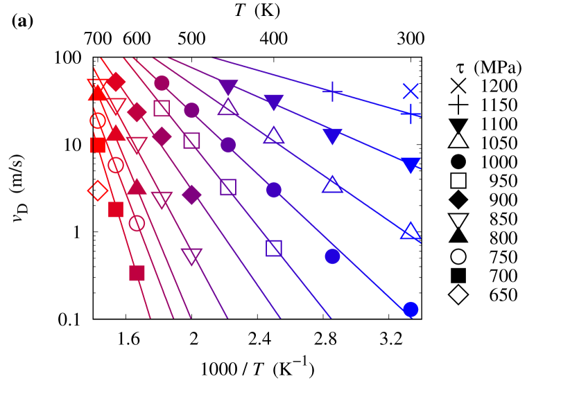
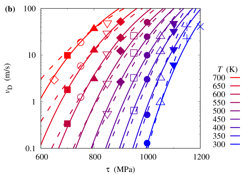
Dislocation velocities obtained from MD simulations for different applied stresses and different temperatures are shown with symbols in Fig. 2. For a given stress , the variation with temperature of the dislocation velocity follows a thermally activated law:
| (1) |
We use the linear variations observed in the Arrhenius plot (Fig. 2a) to extract, for each applied stress, the activation enthalpy and the velocity prefactor . The obtained quantities are shown with symbols in Fig. 3.


| Separate fit | Global fit | |
| (eV) | 67.8 | 101 |
| (MPa) | 1280 | 1540 |
| 0.100 | 0.201 | |
| 1.42 | 2.30 | |
| (K) | 863 | 891 |
| (THz) | 0.040 | 0.054 |
Variations of the activation enthalpy are well described by a Kocks law [26]:
| (2) |
The resulting fit is shown with a dashed line in Fig. 3a and the corresponding four parameters are given in table 1 (column “Separate fit”). As it will be shown below, these parameters are very sensitive to the way the fit is performed and the obtained Kocks law should be mainly understood as a way to interpolate MD results in the corresponding stress range ( MPa), with a poor predictive ability out of this fitting range.
A linear relation between the logarithm of the velocity prefactor and the activation enthalpy is observed (Fig. 3b). This linear relation can be rationalised by writing this velocity prefactor as the product of a constant term which does not depend of the applied stress and of an entropic contribution. Assuming a length dependent regime for dislocation mobility [27], this velocity prefactor is written
| (3) |
where is the length of the dislocation line and therefore the number of possible nucleation sites for a kink pair, the length between two Peierls valleys in the basal glide direction, the fundamental attempt frequency, and the activation entropy. Following Meyer-Neldel compensation rule [28], we assume that activation entropy is proportional to activation enthalpy, , thus leading to the linear relation
| (4) |
in agreement with results of MD simulations (Fig. 3b). The fit of the velocity prefactor as a function of the activation enthalpy (dashed line in Fig. 3b) leads to the parameters and shown in table 1 (column “Separate fit”). As expected [29, 30], the attempt frequency is about one hundredth of the Debye frequency (6 THz [31]) and the scaling temperature is close to the melting temperature (a temperature of 1363 K is obtained with this EAM potential for the melting of the hcp phase [20]).
At the end, we obtain an analytical expression describing the dislocation velocity as a function of the applied stress and of the temperature,
| (5) |
with all unknown parameters obtained from the fits of the activation enthalpy and of the velocity prefactor. The dislocation velocities extracted from MD simulations are compared to this analytical expression in Fig. 2b (dashed line). A reasonable agreement is obtained, except for the lowest (650 MPa) and the highest stresses (1150 and 1200 MPa), for which MD simulations have been performed for too few temperatures, thus preventing a precise determination of the activation enthalpy and of the velocity prefactors. To improve the agreement, we fit directly Eq. 5 to the dislocation velocities obtained by MD for all temperatures and applied stresses, using the four parameters of the Kocks law and the two parameters of the Meyer-Neldel rule as variables (global fit). This leads to the solid lines shown in Fig. 2b which perfectly match the results of MD simulations for all considered stresses and temperatures. The corresponding variations of the activation enthalpy and of the velocity prefactors (solid lines in Fig. 3) are not really different from the ones obtained with the previous fits (dashed lines in Fig. 3) in the stress range MPa, but lead to a slightly different extrapolation out of this range. This is mainly true for the activation enthalpy where the global fit leads to different parameters for the Kocks law (Tab. 1). As a consequence, the obtained analytical law can describe dislocation velocity for stresses higher than 600 MPa where it has been possible to perform MD simulations, but its use for extrapolation at lower stresses appears hazardous. Finally, is is worth pointing that the Peierls stress obtained by this fit of MD results, GPa, is close from the value previously obtained with the same EAM potential (1.79 GPa) by looking for the the stress cancelling the energy barrier for pyramidal and basal glide for a straight screw dislocation [15, 21], i.e. without considering the nucleation and propagation of kink pairs.
2.3 Dislocation trajectory
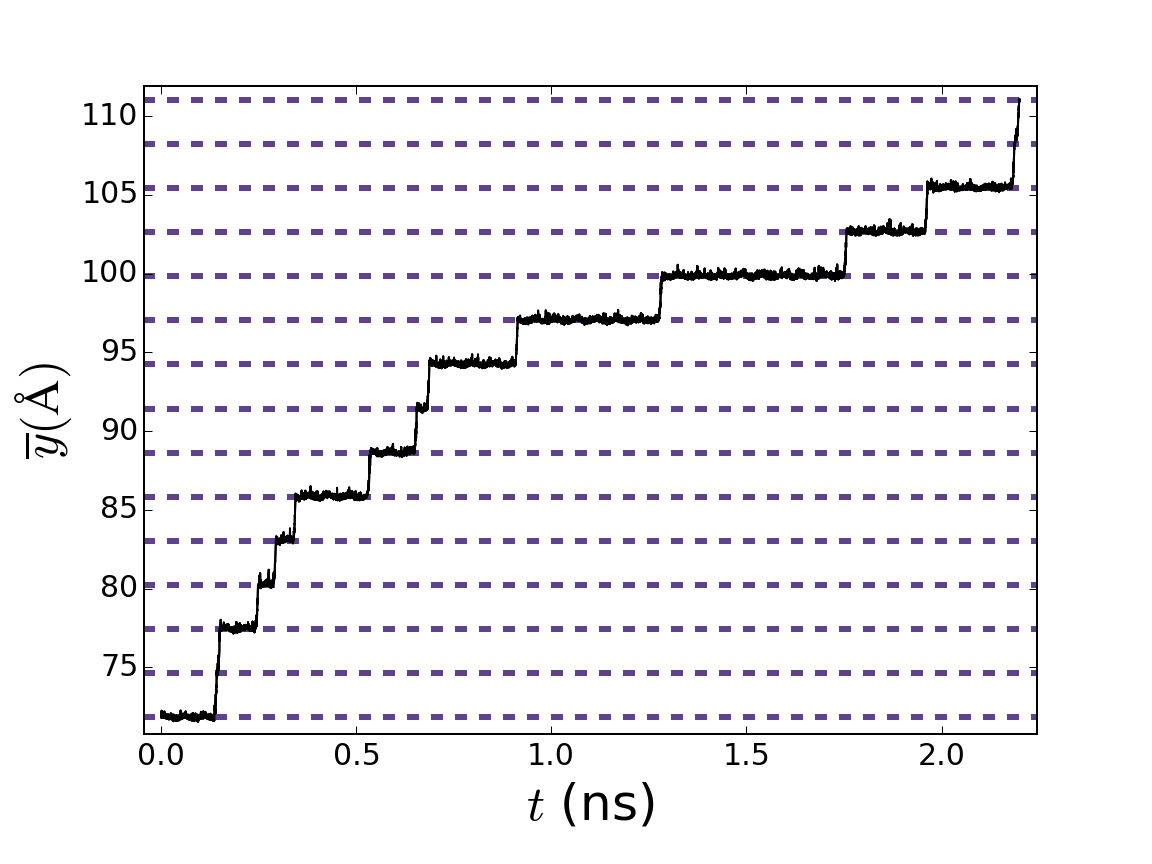
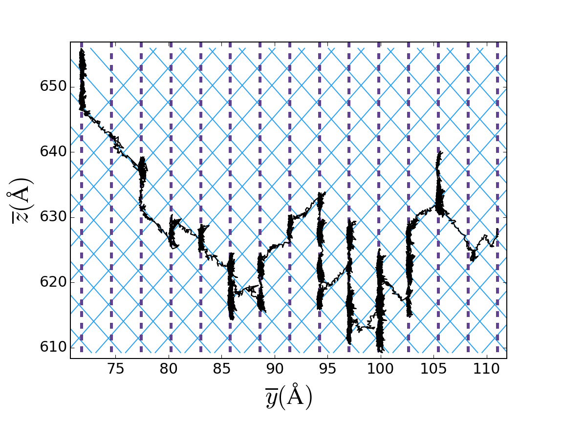
Looking in more details to the dislocation motion (Fig. 4), one sees that it can be decomposed in jump events between two Peierls valleys in the basal plane ( direction) separated by waiting times where the dislocation fluctuates in its prismatic habit plane ( position). As there is no resolved shear stress in the prismatic plane, this fluctuation of the position corresponds to a Brownian motion of the dislocation in this prismatic plane where it can easily glide with almost no energy barrier [1]. The jumps correspond to the nucleation and propagation of a kink pair, as described by the thermally activated mobility law (Eq. 5). The trajectory followed by the dislocation during these jumps does not lie in the basal plane, but in a first order pyramidal plane (Fig. 4). For each jump, the dislocation can glide in one of the two available pyramidal planes. As the only non-null component of the applied stress is , the two pyramidal planes see exactly the same resolved shear stress, thus leading to an equal probability for the dislocation to transit by one of these two planes. As a consequence, the average glide plane coincides with the basal plane. But this is clearly a consequence of our simulation setup where the basal plane is the maximum resolved shear stress plane (MRSSP). With such a glide mechanism where the dislocation glides from one Peierls valleys to the other by transiting through a pyramidal plane, the macroscopic glide plane should correspond to the MRSSP which would be the basal plane only for very specific loading conditions where the other shear stress component is equal to zero. This is in contradiction with experiments [7] which reports basal slip as an elementary slip system. As it will be shown in the next section, the difference may be ascribed to higher applied stresses in molecular dynamics simulations than in experiments.
3 From high to low stress
We now perform nudged elastic band (NEB) calculations [32] to study the mechanisms controlling basal glide in a larger stress range than what can be simulated with MD, in particular at lower stresses. These calculations allow the determination of the minimum energy path for the screw dislocation gliding in a basal plane between two neighbouring Peierls valleys. The simulation setup is the same as for the MD simulations, with only a smaller cell length in the \hkl[0001] direction perpendicular to the basal glide plane ( Å). To ensure that the dislocation is not simply moving as a whole but is gliding through the nucleation and propagation of kink pairs, as observed in MD simulations, the images defining the starting path are initialised with segments lying in one of the two Peierls valleys, with the length of the part in the arrival valley being proportional to the image index in the path.
3.1 Enthalpy barriers for kink nucleation
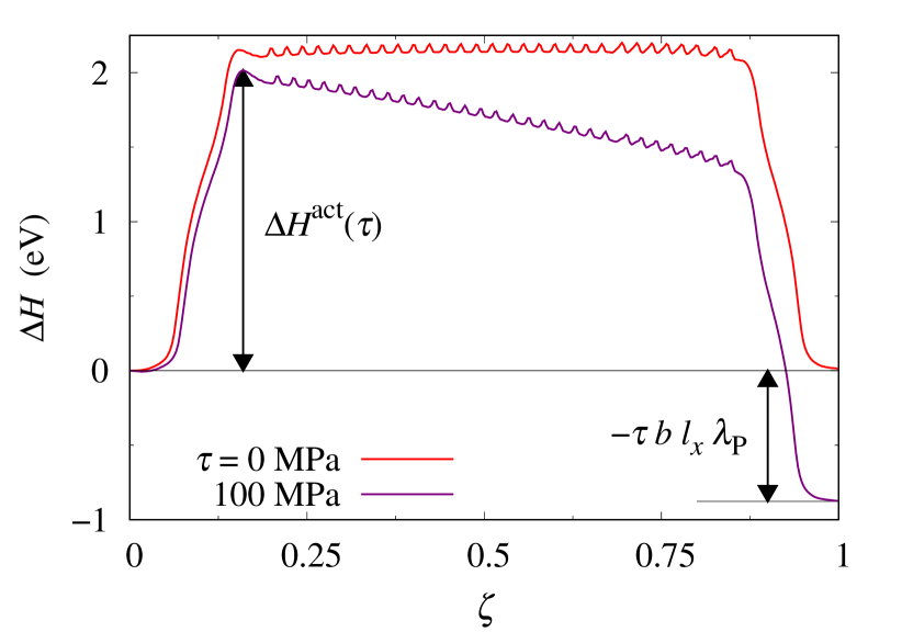
Some enthalpy barriers obtained for basal glide are shown in Fig. 5. In the absence of an applied stress, this barrier is the superposition of an almost constant plateau at 2.2 eV corresponding to the formation energy of a kink pair and small undulations due to the migration of the kinks along the dislocation line, with a migration energy equal to 0.05 eV. Kink migration appears thus much easier than kink pair nucleation. Besides, the formation energy is almost independent from the size of the kink pair, showing that the elastic interaction between kinks can be neglected.
When a positive stress is applied, the enthalpy barrier is shifted with a slope corresponding to the work of the Peach-Koehler forces (Fig. 5), i.e. for the final position () where the whole dislocation of length has glided a distance . The highest enthalpy is met at the beginning of the path when the kink pair is nucleated. This defines the activation enthalpy which controls the basal mobility of the screw dislocation for an applied stress .
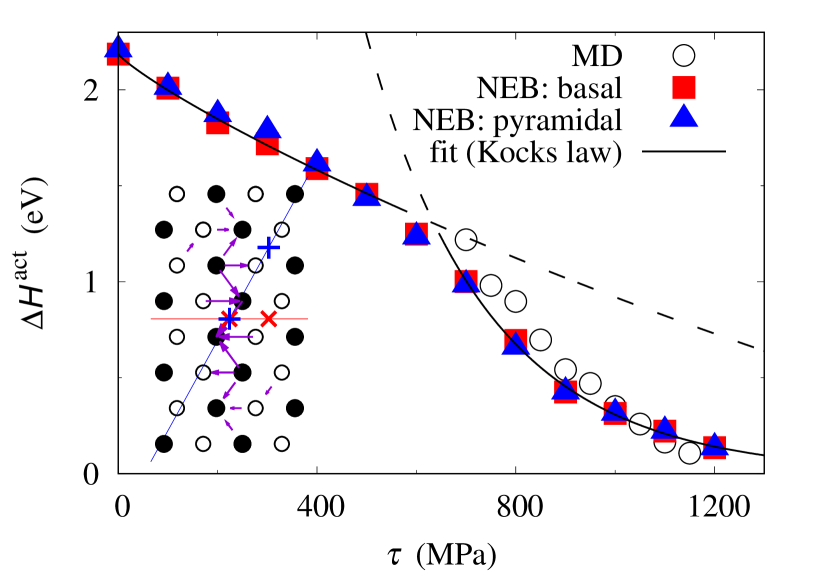
We calculate this activation enthalpy for different applied stresses . Results are shown with red squares in Fig. 6. Activation enthalpies given by NEB calculations can be compared with the ones previously extracted from MD simulations when the applied stress is higher than 700 MPa. A good agreement is obtained between both quantities, further confirming that the glide mechanism given by NEB is the same as the one controlling dislocation mobility in MD simulations. The small differences appearing in Fig. 6 may arise from variations with temperature: MD simulations are performed at finite temperatures whereas NEB calculations are for 0 K.
Looking at the variations with the applied stress of the activation enthalpy, a discontinuity can be seen around 600 MPa. Whereas the activation enthalpy decreases almost linearly with the stress up to 600 MPa, a faster decrease is observed above (Fig. 6). As a consequence, it is not possible to fit the activation enthalpy with a single Kocks law in the whole stress range, but two laws with different parameters are needed. This suggests a change in the mechanism controlling basal glide, with a low- and a high-stress regime which become competitive at 600 MPa. As it will be shown below, this is confirmed by analysing the shape of the critical nucleus associated with this activation enthalpy at different stresses.
3.2 Critical nucleus and activation volume
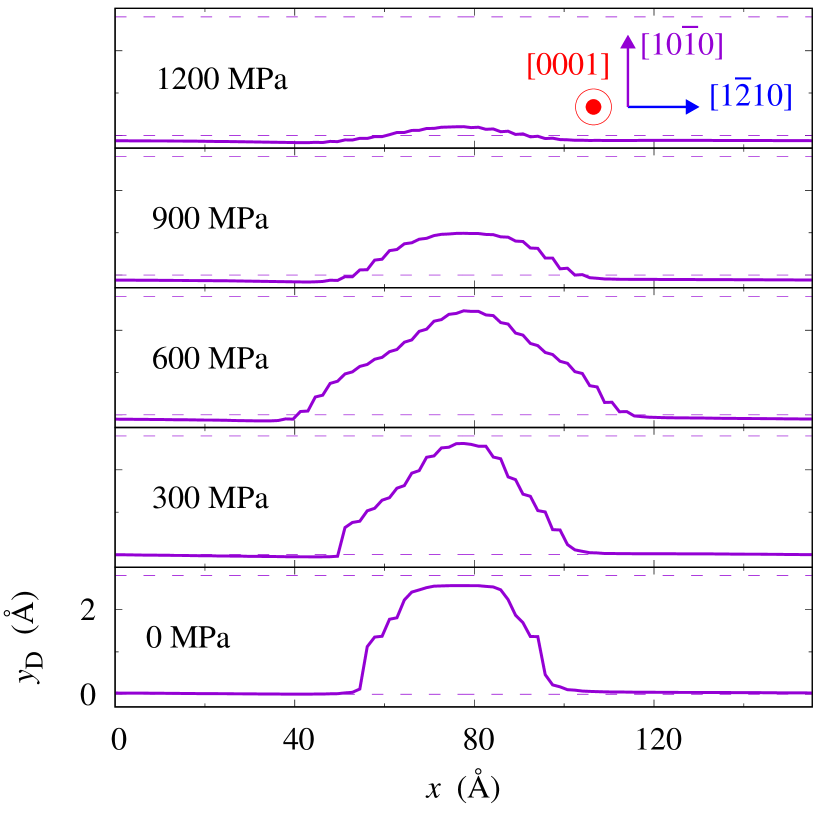
The shape of the critical nucleus is obtained by considering the atomic configuration with the highest enthalpy along the minimum energy path for a given applied stress . The disregistry created by the kinked dislocation is first extracted by taking the displacement difference between atoms located in the plane just above and just below the basal glide plane for every possible position . The solution given by Peierls-Nabarro model is then fitted to the obtained disregistry [33], in strips of width along the line, thus allowing the definition of the dislocation position . The dislocation profiles obtained for the critical nucleus are shows in Fig. 7 for different applied stresses. Similar shapes are obtained when using DXA or when identifying the dislocation position with the average positions of the most energetic atoms in each strip.
For applied stresses lower than 600 MPa, the critical nucleus extends from one Peierls valley to the next valley with its extension in the initial valley becoming wider when the stress increases. Above 600 MPa, the critical nucleus does not jump over the barrier completely up to the next valley and the kink height decreases with an increasing stress. A change of the critical kink pair shape therefore occurs around 600 MPa, at the transition between the low- and high-stress regimes previously seen for the activation enthalpy.
This change of the critical nucleus shape with the applied stress is consistent with predictions of simple models using a line tension approximation to describe the dislocation and integrating its interaction with the crystal trough a 1D Peierls potential (see chap. 4.2 in Ref. [27] for a thorough discussion on these models): at high stress, the critical nucleus corresponds to a dislocation bulge, whereas it converges towards two well-separated kinks at low stress. The transition between these two regimes can be estimated by considering that the bulge correctly describes the critical nucleus as long as its head does not reach the bottom of the next Peierls valley, leading to a minimum stress , with the height of the Peierls barrier [27]. Using the value meV/Å given by this EAM potential for basal glide [15], we obtain MPa. This value is just a little bit lower than the stress, around 600 MPa, where a transition is observed in our simulations for the shape of the critical nucleus and for the variations of the activation enthalpy. But, as it will be shown in the next subsection, the transition between the high- and the low-stress regime cannot be limited to a change of shape of the critical nucleus, as predicted by line tension models. This transition also comes with an evolving atomic structure of the kinks, with important consequences on the dislocation glide plane.
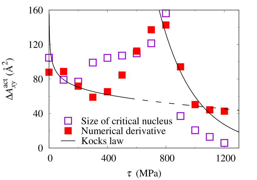
This critical nucleus defines the activation volume for basal glide, i.e. how the activation enthalpy depends on the applied stress. We calculate the area swept by this critical nucleus in the basal plane. Results are shown in Fig. 8 with purple open squares for different applied stresses. This activation area should be equal to the first derivative of the activation enthalpy with the applied stress normalised by the norm of the Burgers vector
| (6) |
The activation area defined by this equation is shown in Fig. 8 with red filled squares, considering numerical derivation of the activation enthalpy given by NEB calculations (Fig. 6). A reasonable agreement is obtained between both definitions of activation areas, illustrating the consistency between the variations of the activation enthalpy and the shape of the critical nucleus. A peak of the activation area appears at 600 MPa, a signature of a change in the mechanism controlling dislocation mobility [27]. The activation area can also be derived from the two Kocks laws used to interpolate the activation enthalpy, leading to two analytical laws which are valid either in the low- or in the high-stress regime, but cannot reproduce the peak at 600 MPa.
3.3 Atomic structure of the kinks
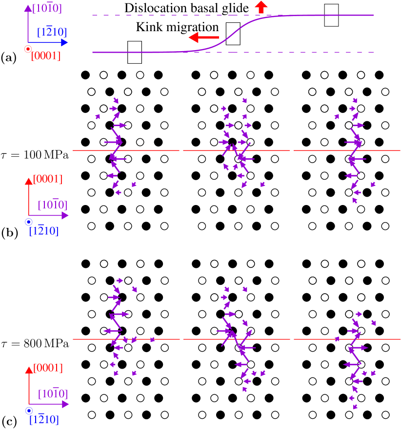
This change of the critical nucleus shape around 600 MPa occurs with a modification of its atomic structure. The configuration of the critical kink pair is shown in Fig. 9 for two different stresses, 100 and 800 MPa, using differential displacement maps to illustrate how the dislocation core varies along the dislocation line. Far from the kink, the core adopts its ground state configuration and is dissociated in the prismatic plane. The parts on the left and on the right of the kink are lying in two different Peierls valleys separated by one minimal distance in the direction of basal glide. At low stress (Fig. 9b), these dislocation segments in the initial and arrival Peierls valleys have their centres located exactly in the same basal plane which corresponds to the glide plane. In its kinked part, the dislocation adopts a configuration with a mixture of basal and prismatic spreading. At low stress, the kinked dislocation is therefore fully lying in the basal plane where it is gliding. The picture is different at higher stresses, as the dislocation segments in the initial and arrival Peierls valleys have glided in their prismatic planes in opposite direction and are not located anymore in the same basal plane (Fig. 9c). The centres of these segments now belong to the same pyramidal plane. In agreement with these positions of the left and right parts of the dislocation, the core in the kinked part of the line is spread in this pyramidal plane. NEB calculations therefore predict that the critical nucleus is lying in a pyramidal plane at high stress, thus explaining the pyramidal jumps observed in MD simulations when the dislocation is gliding in a basal plane.
One can legitimately wonder how this change of the kink structure with the applied stress depends on the choice of the interatomic potential. The EAM potential #3 of Mendelev and Ackland [20] is known to stabilize a metastable configuration of the straight screw dislocation corresponding to a dissociation in two Shockley partials in the basal plane, whereas this basal structure is found unstable with ab initio calculations [1]. Although the kinked part of the screw dislocation partly spreads in the basal plane in the low stress regime (Fig. 9b), the atomic structure completely differs from a full dissociation in two partials. It seems therefore unlikely that this structure of the kinked dislocation is a consequence of the basal dissociation of the straight screw dislocation artificially stabilized by this empirical potential, especially as this metastable configuration has a much higher energy than the ground state ( meV Å-1). On the other hand, the kink structure at high stress (Fig. 9c) looks similar to the dissociation of the screw dislocation in two partials in the pyramidal plane obtained not only with this empirical potential but also with ab initio calculations [15, 21, 2].
3.4 Basal and pyramidal slip
NEB calculations confirm that basal slip is composite at high stress and can be decomposed in elementary prismatic and pyramidal slip events, in agreement with the glide mechanism already revealed by ab initio calculations for straight dislocations [15]. But a change of the glide mechanism, corresponding to a change of the kink structure, is seen at low stress. At low stress, dislocation glide is fully resolved in the basal plane and basal slip becomes an elementary slip system, thus in agreement with experimental observations [11, 7, 12].
Basal and pyramidal slips appear thus intertwined. To further demonstrate this link, additional NEB calculations have been performed for a screw dislocation gliding in a pyramidal plane by nucleation and propagation of a kink pair. The setup is the same as for NEB calculations of basal glide but with a different position of the dislocation final configuration so as to lead to pyramidal slip (see inset in Fig. 6 where the initial and final positions are shown with blue crosses). Whatever the applied stress, NEB calculations lead to exactly the same activation enthalpy for pyramidal and basal slip (Fig. 6). This can be rationalised by looking in more details to the mechanism for pyramidal slip. At low stress, the dislocation glide is composite and proceeds trough nucleation of a kink pair in the basal plane preceded and followed by easy slip of the screw dislocation in its initial and arrival prismatic plane. On the other hand, at high stress the dislocation glide by nucleation of a kink pair directly in the pyramidal plane.
Basal and pyramidal glide of screw dislocations are therefore two facets of the same deformation mode, with basal and pyramidal glide being favoured respectively at low and high stress. Experimental conditions usually correspond to the low stress regime, thus explaining why basal glide is the secondary slip system usually reported for dislocations [3, 8, 5, 9, 10, 6, 7]. In particular, this preference for basal slip at low stress is fully compatible with the TEM observations of Caillard et al. [7] during in situ tensile experiments showing that basal glide is an elementary slip system and not a combination of two different slip systems. Experimental evidences of pyramidal slip also exist. In particular, Tenckhoff [16] mentioned that “in regions of high stress concentrations, such as grain boundaries, \hkl10-11 slip traces occur”, thus in perfect agreement with the evolution of slip activity with the applied stress deduced from our NEB calculations.
3.5 Comparison with experiments
A good agreement is therefore obtained between atomistic simulations and in situ TEM straining experiments [7], both showing that basal glide is the secondary slip system activated at low stress for \hkl¡a¿ dislocations and that it is controlled by a Peierls mechanism, i.e. the nucleation and propagation of kink pairs on screw dislocations. This basal glide activated below 600 MPa agrees with compression experiments of micropillars realised by Wang et al. [12] on single-crystals with a high Schmid factors on basal slip systems, as these experiments show only basal slip traces, without any evidence of pyramidal slip, for resolved shear stresses ranging from 50 to 150 MPa. Besides this agreement on the activation of basal slip at low stress and the corresponding Peierls mechanism, it is worth looking how the mobility law extracted from these simulations (Eq. 5) and the obtained parameters compare with similar laws deduced from experiments [5, 12].
Akhtar [5] fitted a Norton law on tensile tests experiments on single crystals oriented to activate basal slip in a temperature range 850-1100 K. The activation energy he obtained, 1.48 eV, is lower than the one given by NEB calculations in the limit of a vanishing stress, 2.2 eV (Fig. 6). Such a difference is not surprising as the empirical potential used for the atomic simulations is known to overestimate the Peierls energy barrier for basal glide of a straight dislocation: this potential leads to a 25 meV/Å barrier whereas the barrier predicted by ab initio calculations is only 9 meV/Å [15]. One therefore expects that the activation energy controlling basal glide in zirconium is lower than the value, 2.2 eV, given by this potential.
Akhtar [5] also measured activation volumes. The obtained values are above , much higher than the ones around given by the atomic simulations. As noticed by Akhtar such high values are not compatible with a Peierls mechanism. He proposed that basal glide would operate by a cross-slip mechanism. Such a mechanism does not correspond to the one revealed by atomistic simulations. Besides, it would necessitate that the screw dislocation can adopt a metastable configuration which can easily glide in basal planes. The best configuration would be a core dissociated in a basal plane, but ab initio calculations have shown that such a basal core is unstable [1]. Finally this cross-slip mechanism would lead to jerky and intermittent motion of screw dislocations, in contradiction with the smooth motion seen in TEM during in situ straining experiments [7]. Therefore, the high value obtained by Akhtar for the activation volume is more likely the signature of another mechanism limiting basal glide in the high temperatures explored in these experiments. Impurities, which should be mobile at these temperatures, may impede dislocation motion, leading to a hardening contribution which would exceed the Peierls mechanism controlling basal glide in pure zirconium.
Both Caillard et al. [7] and Wang et al. [12] indeed mentioned that basal glide becomes athermal at 573 K, thus well below the temperatures in Akhtar experiments where dislocations should not feel anymore the lattice friction, even when gliding in basal planes. An approximate athermal temperature can be estimated from the mobility law (Eq. 5) extracted from atomic simulations (See Eq. 29 in Ref. [34]) using parameters obtained in the low stress regime for the Kocks law and assuming that parameters and are the same as the ones given by MD in the high stress regime. For reasonable values of the dislocation density (– m-2) and of the strain rate (– s-1), the obtained athermal temperature is between 450 and 570 K, thus further confirming that the lattice friction opposing glide should have a negligible effect in the high-temperatures regime explored by Akhtar [5].
4 Conclusion
Atomistic simulations show that \hkl¡a¿ screw dislocations in zirconium can glide in basal and pyramidal planes while remaining dissociated in the prismatic plane. The motion proceeds through the nucleation and propagation of kink-pairs and is thus thermally activated. The activation enthalpy entering dislocation mobility law, and its temperature dependence, are well described by a Kocks law and the Meyer-Neldel compensation rule. These simulations confirm that basal and pyramidal slip are intimately intertwined with two different stress regimes. At high stress, pyramidal glide of the screw dislocation is the elementary event controlling these two secondary slip systems and basal glide is a combination of easy prismatic glide and pyramidal glide. One thus recovers the mechanism already revealed by ab initio calculations for the glide of a straight screw dislocation [15]. On the other hand, at low stress, kinks nucleate in the basal plane, allowing for a glide of the screw dislocation fully resolved in this basal plane, and pyramidal slip becomes composite. Basal glide appears thus as an elementary slip system in hcp zirconium at low stress, in agreement with experiments showing well defined slip traces in the basal planes [11, 7].
With this new understanding of the mechanisms controlling basal and pyramidal slip in pure zirconium, it appears possible now to study the impact of the different alloying elements on the activity of these secondary slip systems. As described in the introduction, pyramidal slip of \hkl¡a¿ dislocations appear more likely in zirconium alloys than in pure zirconium. Among the different addition elements met in zirconium alloy, oxygen appears as one with the most prominent effect, with oxygen promoting dislocation cross-slip in pyramidal planes [35, 36].
Despite the difference in the ground state of the \hkl¡a¿ screw dislocation, spread on the prismatic plane for zirconium and on the first order pyramidal plane for titanium [2], secondary slip in the basal and pyramidal planes is similar in both metals above room temperature. Basal slip appears also easier than pyramidal slip in titanium, with screw dislocations gliding through a slow and viscous motion compatible with a Peierls mechanism [7]. As ab initio calculations have shown that a \hkl¡a¿ screw dislocation dissociated in a basal plane is unstable in titanium [37], basal glide in titanium is also realized without any basal dissociation. The same mechanism, where the screw dislocation glides in a basal planes trough the nucleation and propagation of kink-pairs while remaining dissociated in another plane, either prismatic or pyramidal, is therefore expected in titanium.
Acknowledgements - The authors thank Thomas Swinburne and Mihai-Cosmin Marinica for fruitful exchanges on entropy contributions to activation free enthalpy, and Daniel Caillard for long-standing discussions on basal glide in zirconium and on Peierls mechanism. This work was performed using HPC resources from GENCI-CINES and -TGCC (Grants 2020-096847) and is funded by the project Transport & Entreposage of the French Institut Tripartite CEA-EDF-Framatome.
References
References
- [1] E. Clouet, Screw dislocation in zirconium: An ab initio study, Phys. Rev. B 86 (2012) 144104. doi:10.1103/PhysRevB.86.144104.
- [2] E. Clouet, D. Caillard, N. Chaari, F. Onimus, D. Rodney, Dislocation locking versus easy glide in titanium and zirconium, Nat. Mater. 14 (2015) 931–936. doi:10.1038/nmat4340.
- [3] J. Bailey, Electron microscope studies of dislocations in deformed zirconium, J. Nucl. Mater. 7 (1962) 300–310. doi:10.1016/0022-3115(62)90247-7.
- [4] A. Akhtar, A. Teghtsoonian, Plastic deformation of zirconium single crystals, Acta Metall. 19 (1971) 655–663. doi:10.1016/0001-6160(71)90019-8.
- [5] A. Akhtar, Basal slip in zirconium, Acta Metall. 21 (1973) 1–11. doi:10.1016/0001-6160(73)90213-7.
- [6] F. Long, M. R. Daymond, Z. Yao, Deformation mechanism study of a hot rolled Zr-2.5Nb alloy by transmission electron microscopy. I. Dislocation microstructures in as-received state and at different plastic strains, J. Appl. Phys. 117 (2015) 094307. doi:10.1063/1.4913605.
- [7] D. Caillard, M. Gaumé, F. Onimus, Glide and cross-slip of a -dislocations in Zr and Ti, Acta Mater. 155 (2018) 23–34. doi:10.1016/j.actamat.2018.05.038.
- [8] J. I. Dickson, G. B. Craig, Room-temperature basal slip in zirconium, J. Nucl. Mater. 40 (1971) 346–348. doi:10.1016/0022-3115(71)90103-6.
- [9] H. Francillette, B. Bacroix, M. Gaspérini, J. Béchade, Effect of initial textures on deformation mechanisms and texture evolutions of Zr polycrystals deformed by channel-die compression tests, Mater. Sci. Eng. A 234-236 (1997) 974–977. doi:10.1016/s0921-5093(97)00410-3.
- [10] H. Francillette, B. Bacroix, M. Gaspérini, J. L. Béchade, Grain orientation effects in Zr702 polycrystalline samples deformed in channel die compression at room temperature, Acta Mater. 46 (1998) 4131–4142. doi:10.1016/s1359-6454(98)00121-9.
- [11] J. Gong, T. B. Britton, M. A. Cuddihy, F. P. Dunne, A. J. Wilkinson, prismatic, basal, and slip strengths of commercially pure Zr by micro-cantilever tests, Acta Mater. 96 (2015) 249–257. doi:10.1016/j.actamat.2015.06.020.
- [12] S. Wang, F. Giuliani, T. B. Britton, Variable temperature micropillar compression to reveal basal slip properties of zircaloy-4, Scr. Mater. 162 (2019) 451–455. doi:10.1016/j.scriptamat.2018.12.014.
- [13] D. Caillard, M. Rautenberg, X. Feaugas, Dislocation mechanisms in a zirconium alloy in the high-temperature regime: An in situ TEM investigation, Acta Mater. 87 (2015) 283–292. doi:10.1016/j.actamat.2015.01.016.
- [14] F. Long, F. Xu, M. R. Daymond, Temperature dependence of the activity of deformation modes in an HCP zirconium alloy, Metall. Mater. Trans. A 44 (2013) 4183–4193. doi:10.1007/s11661-013-1758-z.
- [15] N. Chaari, E. Clouet, D. Rodney, First-principles study of secondary slip in zirconium, Phys. Rev. Lett. 112 (2014) 075504. doi:10.1103/PhysRevLett.112.075504.
- [16] E. Tenckhoff, Review of deformation mechanisms, texture, and mechanical anisotropy in zirconium and zirconium base alloys, Journal of ASTM International 2 (2005) 12945. doi:10.1520/jai12945.
- [17] M. Rautenberg, X. Feaugas, D. Poquillon, J.-M. Cloué, Microstructural characterization of creep anisotropy at 673K in the M5(R) alloy, Acta Mater. 60 (2012) 4319–4327. doi:10.1016/j.actamat.2012.04.001.
- [18] J. Drouet, L. Dupuy, F. Onimus, F. Mompiou, A direct comparison between in-situ transmission electron microscopy observations and dislocation dynamics simulations of interaction between dislocation and irradiation induced loop in a zirconium alloy, Scripta Mater. 119 (2016) 71–75. doi:10.1016/j.scriptamat.2016.03.029.
- [19] M. Gaumé, P. Baldo, F. Mompiou, F. Onimus, In-situ observation of an irradiation creep deformation mechanism in zirconium alloys, Scr. Mater. 154 (2018) 87–91. doi:10.1016/j.scriptamat.2018.05.030.
- [20] M. I. Mendelev, G. J. Ackland, Development of an interatomic potential for the simulation of phase transformations in zirconium, Philos. Mag. Lett. 87 (2007) 349–359. doi:10.1080/09500830701191393.
- [21] N. Chaari, E. Clouet, D. Rodney, First order pyramidal slip of screw dislocations in zirconium, Metall. Mater. Trans. A 45 (2014) 5898–5905. doi:10.1007/s11661-014-2568-7.
- [22] D. Rodney, Activation enthalpy for kink-pair nucleation on dislocations: Comparison between static and dynamic atomic-scale simulations, Phys. Rev. B 76 (2007) 144108. doi:10.1103/PhysRevB.76.144108.
- [23] S. Plimpton, Fast parallel algorithms for short-range molecular dynamics, J. Comput. Phys. 117 (1995) 1–19. doi:10.1006/jcph.1995.1039.
- [24] A. Stukowski, V. V. Bulatov, A. Arsenlis, Automated identification and indexing of dislocations in crystal interfaces, Modell. Simul. Mater. Sci. Eng. 20 (2012) 085007. doi:10.1088/0965-0393/20/8/085007.
- [25] A. Stukowski, Visualization and analysis of atomistic simulation data with OVITO – the open visualization tool, Modell. Simul. Mater. Sci. Eng. 18 (2010) 015012. doi:10.1088/0965-0393/18/1/015012.
- [26] U. F. Kocks, A. S. Argon, M. F. Ashby, Progress in materials science, in: Thermodynamics and kinetics of slip, Vol. 19, Pergamon Press, 1975.
-
[27]
D. Caillard, J. L. Martin,
Thermally
activated mechanisms in crystal plasticity, Pergamon, Amsterdam, 2003.
URL http://www.sciencedirect.com/science/bookseries/14701804/8 - [28] W. Meyer, H. Neldel, Relation between the energy constant and the quantity constant in the conductivity–temperature formula of oxide semiconductors, Z. tech. Phys. 18 (1937) 588–593.
- [29] S. Saroukhani, L. Nguyen, K. Leung, C. Singh, D. Warner, Harnessing atomistic simulations to predict the rate at which dislocations overcome obstacles, J. Mech. Phys. Solids 90 (2016) 203–214. doi:10.1016/j.jmps.2016.02.016.
- [30] G. Esteban-Manzanares, R. Santos-Güemes, I. Papadimitriou, E. Martinez, J. LLorca, Influence of the stress state on the cross-slip free energy barrier in Al: An atomistic investigation, Acta Mater. 184 (2020) 109–119. doi:10.1016/j.actamat.2019.10.055.
- [31] C. Kittel, Introduction to Solid State Physics:, 7th Edition, Wiley, New York, 1996.
- [32] G. Henkelman, G. Jóhannesson, H. Jónsson, Methods for finding saddle points and minimum energy paths: theoretical methods in condensed phase chemistry, in: S. D. Schwartz (Ed.), Progress in Theoretical Chemistry and Physics, Vol. 5, Springer Netherlands, 2000, Ch. 10, pp. 269–302. doi:10.1007/0-306-46949-9_10.
- [33] E. Clouet, C. Varvenne, T. Jourdan, Elastic modeling of point-defects and their interaction, Comp. Mater. Sci. 147 (2018) 49–63. doi:10.1016/j.commatsci.2018.01.053.
- [34] E. Clouet, B. Bienvenu, L. Dezerald, D. Rodney, Screw dislocations in bcc transition metals: from ab initio to yield criterion, C. R. Phys. in press. doi:10.5802/crphys.75.
- [35] D. H. Baldwin, R. E. Reedhill, Some effects of oxygen on tensile deformation of polycrystalline zirconium, Trans. AIME 242 (1968) 661.
- [36] N. Chaari, D. Rodney, E. Clouet, Oxygen - dislocation interaction in zirconium from first principles, Acta Mater. 132 (2017) 416–424. doi:10.1016/j.actamat.2017.05.008.
- [37] P. Kwasniak, E. Clouet, Basal slip of screw dislocations in hexagonal titanium, Scr. Mater. 162 (2019) 296–299. doi:10.1016/j.scriptamat.2018.11.027.