Skyrmion Dynamics in the Presence of Deformation
Abstract
Magnetic skyrmions are topological spin textures promising for future high-density and non-volatile memory. It is crucial to understand the current-driven skyrmion dynamics in the presence of deformation, of which an analytical model, however, remains elusive. Here we extend Thiele’s model by considering both the radial and tangential forces. Our model attributes the skyrmion deformation to the current-induced rotational symmetry breaking, which includes magnetization canting and domain wall width variation. Our predictions of skyrmion radius and nonlinear dynamics are consistent with micromagnetic simulation results. Besides, we show that by applying an in-plane magnetic field, the deformation of a skyrmion can be suppressed, and even the compression of a skyrmion can be achieved. Our model provides a generic way to analyze the skyrmion deformation and may inspire applications based on nonlinear skyrmion dynamics.
Introduction.— Skyrmion is a topological soliton first proposed by Skyrme to solve the nonlinear sigma model [1]. Recently, magnetic skyrmions were generated and observed in B20 chiral magnets and ferromagnet/heavy metal bilayer systems with Dzyaloshinskii-Moriya interaction (DMI) [2, 3, 4, 5, 6, 7, 8]. Due to its non-trivial topological charge, skyrmion is topologically protected and can be driven by spin-transfer torque (STT) at ultralow current densities [9, 10, 11], promising for information carrier in non-volatile memory and other spintronic devices [12, 13, 14, 15].
Manipulation of skyrmions can be achieved by current injection in a ferromagnet/heavy metal bilayer [16, 17, 18, 19]. The charge current in the heavy metal layer with strong spin-orbit coupling induces a spin current in out-of-plane direction, exerting spin-orbit torque (SOT) on the ferromagnetic layer to drive the skyrmion. For high-speed skyrmion applications, high drive current densities are needed. Experimental results have suggested that skyrmion deformation can occur during the large current-driven motion [19, 18, 20]. Theoretically, STT- or SOT-induced skyrmion deformation has been studied using micromagnetic simulations and semianalytical approach [21, 22, 23]. Semianalytical means that micromagnetic simulation is still needed in analytical modeling.
Although the Thiele’s approach [24] is very successful in explaining the current-driven skyrmion motion at low drive currents [25, 11, 26], and it has been extended to include antiferromagnetic spin textures [27, 28], magnon effect [29], etc., there is no pure analytical model describing the deformation and nonlinear dynamics of current-driven skyrmions. It is highly desired to extend Thiele’s approach to better understand the skyrmion dynamics in the presence of high current-induced deformation [30]. In this work, we establish an analytical model including current-induced radial and tangential forces and successfully predict skyrmion radius and critical current density without the need of micromagnetic simulation. Exceeding this critical current density, the skyrmion breaks down. Induced by tangential Thiele’s force density, the magnetization canting contributes the most to the symmetry breaking. We also find that the domain wall width depends on the skyrmion radius. Unlike most studies that focus on the translational part integration of Thiele’s equation leading to skyrmion motion velocity, we calculate the integration of the radial part of Thiele’s equation and obtain skyrmion radius. With the obtained skyrmion radius, we can accurately describe nonlinear skyrmion dynamics. Moreover, we propose a method to suppress the deformation by applying an in-plane magnetic field.
Model and Methods.— The dynamics of a ferromagnetic system is governed by the Landau–Lifshitz–Gilbert (LLG) equation [31] with a damping-like SOT term,
| (1) |
where is the gyromagnetic ratio, is the effective field, is the Gilbert damping constant, is the damping-like spin orbit torque and is the polarization direction. Assume that is along direction, i.e. and electron current along direction, i.e. , where and are unit vectors in Cartesian coordinates.
Using Thiele’s approach [24, 32], we can substitute each term in the LLG equation with an equivalent field, and define corresponding force densities, , , runs . are the effective fields corresponding to the terms in Eq.(1), and the exact definitions are given in Eqs.(S5)-(S8) in supplemental material [33].
A skyrmion in steady-state motion must satisfy everywhere, where is gyroscopic force density, is effective-field force density, is current-induced SOT force density, and is dissipative force density. Moreover, these forces can be decomposed into radial force and tangential force, , where is the radial unit vector and is the tangential unit vector.
For simplicity, we define radial force, which is the integral of radial force density, as,
| (2) |
where is the whole plane and is the unit radial vector in the polar coordinates centered at the skyrmion center (the center of mass). Since all the force densities balance each other, their radial force density integrals or radial forces must balance as well, that . , and are related to current and skyrmion motion, which cause the deformation of skyrmion. So we define the expanding force to be the sum of these three radial forces, . To the contrary, is the restoring force, and we let . It will be shown later that both and depend on skyrmion radius and domain wall width parameter . By solving
| (3) |
we are able to find and . How to accurately solve Eq.(3) without using micromagnetic simulation is the major contribution of this work.
The restoring force is determined by effective field . contains four components, i.e., , which correspond to Heisenberg exchange interaction, DMI, effective anisotropy, and external magnetic field. , , where is the exchange stiffness, is the effective anisotropy constant. Effective anisotropy contains magnetocrystalline anisotropy and demagnetization field in ultrathin film with perpendicular magnetization [34], that , where is the uniaxial anisotropy constant. For Néel-type skyrmion stabilized by interfacial DMI, , and for Bloch-type skyrmion stabilized by bulk DMI, [26, 34].
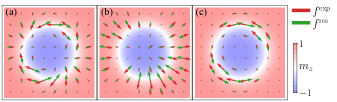
Rotational Symmetry Breaking of Skyrmion.— If a steady-state motion skyrmion takes a rotation-symmetric magnetization distribution similar to a ground state skyrmion, the expanding force will be zero. SOT breaks the rotational symmetry of skyrmion, and induces a non-trivial . We will show that the breaking of rotational symmetry comes from two parts, i.e., magnetization canting and domain wall compression and expansion.
Here, we discuss the Néel-type skyrmion case, where skyrmion domain wall profile is . If no in-plane external field or current is applied, the direction of magnetization at each point of a ground state skyrmion will have no tangential component. However, a current will induce magnetization canting as shown in Fig.2(a). The effect of an in-plane magnetic field is similar to that of a current [21].
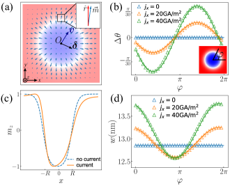
To quantitatively describe the canting, we use polar coordinates centered at skyrmion center and let . Note that the canting is equal to the tangential deviation of , i.e. . We show below that the canting is determined by tangential Thiele’s force densities, which sum up to be zero as
| (4) |
Although Eq.(4) cannot be solved analytically, we can still estimate . We ignore insignificant terms and obtain [33], where
| (5) |
is the characteristic vector of canting shown in Fig.2(a), being the skyrmion velocity. It suggests that the canting is proportional to the skyrmion velocity. The canting vector , perpendicular to the velocity, characterizes the amplitude of the asymmetrical deformation of the skyrmion spin configuration.
With this estimation of , it can be shown that terms in the expanding force are [33],
| (6a) | |||||
| (6b) | |||||
| (6c) | |||||
The skyrmion velocity can be computed by [23, 32],
| (7a) | |||||
| (7b) | |||||
| (7c) | |||||
Here is the topological charge of skyrmion defined by [15], and are the driving factor and damping factor in Thiele’s equation respectively. Eq.(7c) is derived from a rigid skyrmion as shown in Ref.[23].
For current-driven skyrmion, is different from of ground state skyrmion. Also, along different azimuthal direction is not the same, i.e. is a function of polar angle , as shown in Figs.2(c)(d). Without loss of validity, we can use average , i.e., .
The total Hamiltonian of a skyrmion includes exchange interaction, DMI, magnetocrystalline anisotropy and Zeeman energy due to external field. For ground state skyrmion without an external field, the skyrmion radius is given by [35]. The steady-state of skyrmion motion is a quasi-static state and the skyrmion should minimize its total energy under the constraint of Thiele’s equation. By minimizing the total energy, we have the relation between and for a moving skyrmion [33],
| (8) |
Unlike expectations in most papers that the domain wall is almost rigid [23], we found that actually increases with . This is also an improvement for normal ground state domain wall width parameter equation [34].
We then consider the effect of in-plane external field . It induces another canting vector [33]. Together with the current-induced canting, the net canting vector is . If direction in-plane field is applied, two canting vectors will partially cancel, and the expanding forces in Eq.(6) will consequently be reduced and even be reversed.
In Eq.(1), we only consider damping-like SOT. Field-like SOT acts like an in-plane external field perpendicular to the current direction [18]. Therefore, we can use an equivalent in-plane field to describe field-like SOT.
To better understand the model, we can make approximations for and and analytically solve Eq.(3). The expanding force is approximately a quadratic function of both and , , where . The restoring force is a linear function of , , where . Both and can be analytically determined [33], but their closed forms are too complicated to be written down. Approximately, and are constant [33]. Eq.(3) is therefore reduced to a quadratic equation, of which the physical solution is,
| (9) |
The solution for only exists for smaller than some critical current density , and . The radius at is .
In the presence of -direction in-plane external field, the expanding force is attached with an additional term, [33]. We can expand the effect of external field to the first order. In such case, and [33], where is the skyrmion radius without external field, determined by Eq.(9). These approximations reveal that the critical current increases and the skyrmion radius can decrease if a sufficiently large direction in-plane field is applied.
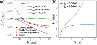
Verification Using Micromagnetic Simulation.— Since for fixed material parameters and , and only depend on and . is determined by Eq.(8), and can also be calculated by parameters, and by Eq.(7). As a result, numerically solving Eq.(3) leads to , the radius of the skyrmion in steady-state motion, called saturation radius. However, when is lager than a threshold current density, skyrmion has no steady-state motion, as shown in Fig.3(a). We can find the critical current density by solving Eq.(3). In Fig.3(b), we show two special cases, where one case with a drive current smaller than has a saturation radius and the other one with a drive current larger than does not.
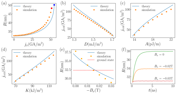
We use the Mumax3 software to perform micromagnetic simulations [36]. The default parameters are , thickness [18, 23]. We apply and adjust the -direction current density, , and record skyrmion saturation radius. Also, the existence of saturation radius is determined by testing whether the skyrmion radius diverges with time, as illustrated in Fig.3(b). We compare the simulation results of current-dependent saturation radius with what our model predicts, and we achieve a good agreement, as shown in Fig.4(a).
We then verify our prediction for the critical current density . is determined by the maximum such that solution still exists for Eq.(3). For each parameter setting, we use binary search to find the critical current using micromagnetic simulation. We test for , and respectively. The results are shown in Figs.4(b)-(d) and are consistent with the predictions given by the analytical model. We can further understand the result from the approximation model, Eq.(9). , where is constant [33]. The dependence of on , and can be easily understood using the approximation model now.
As predicted by the analytical model and the approximation model, applying an direction in-plane field can suppress the deformation. Our predicted saturation radii and the micromagnetic simulation results in the presence of the external field are shown in Figs.4(e)(f), which show a quantitative agreement. Our approximation model provides the insight that in-plane external field can cancel the magnetization canting caused by current, suppress skyrmion deformation, and even cause skyrmion to contract under current injection.
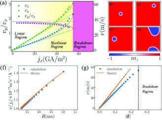
At last, we describe the nonlinear velocity of skyrmion in the presence of deformation, which goes beyond Thiele’s equation in the linear regime. The change in skyrmion radius induces nonlinear response of skyrmion velocity by Eq.(7), as shown in Fig.5(a). Our analytical model provides a much better predictions about velocity and skyrmion Hall angle than the linear model, where only translational parts of forces are considered. We also show snapshots of skyrmion dynamics at different regimes in Figs.5(b)-(e). We can see that our predicted velocity and skyrmion Hall angle are consistent with the micromagnetic simulation. From the simulation results in Fig.5(f), we find that the mobility of the skyrmion, defined as , increases as the skyrmion radius increases. This is consistent with our analytical model and Eqs.(7). To investigate how rotational symmetry breaking affects the skyrmion dynamics, we show the relation between the skyrmion velocity and the magnetization canting, which is the asymmetric deformation of the skyrmion spin configuration in Fig.5(g). The velocity increases quasi-linearly with the magnetization canting, which is consistent with the analytical model and Eq.(5). The quantitative discrepancy between the simulated and the theoretical canting is expected to resolve by further improving the assumptions from Eq.(4) to Eq.(5).
In supplemental material [33], an empirical correction of the model is proposed, leading to a significant improvement in the quantitative agreement. Besides, we generalize our model to cases that involve out-of-plane external field and deformation dynamics of Bloch-type skyrmions, and show our model works very well for these cases.
In conclusion, our analytical and nonlinear model accurately describes the deformation and velocity of SOT-driven skyrmion. It captures the essential physics of skyrmion deformation, that is the rotational symmetry breaking of SOT-driven skyrmion. From this foothold we are able to suppress skyrmion deformation by applying in-plane field, which also has a sizeable effect on skyrmion symmetry. Our results suggest that the spatial symmetry breaking in topological spin textures may significantly affect their dynamics, which can be potentially utilized to build nonlinear functional devices [37]. Moreover, we anticipate that our model can be extended to describe nonlinear dynamics of other topological spin textures such as antiferromagnetic skyrmions and bimeron.
We appreciate fruitful discussions with Motohiko Ezawa and Se Kwon Kim. Z.C. acknowledges the support from Zheyu Ren and Cheuk Pan Fong. The authors at HKUST acknowledge funding support from the Shenzhen-Hong Kong-Macau Science and Technology Program (Category C, Grant No. SGDX2020110309460000), Research Grant Council—Early Career Scheme (Grant No. 26200520), and the Research Fund of Guangdong-Hong Kong-Macao Joint Laboratory for Intelligent Micro-Nano Optoelectronic Technology (Grant No. 2020B1212030010). Y.Z. acknowledges the support by Guangdong Special Support Project (2019BT02X030), Shenzhen Fundamental Research Fund (Grant No. JCYJ20210324120213037), Shenzhen Peacock Group Plan (KQTD20180413181702403), Pearl River Recruitment Program of Talents (2017GC010293) and National Natural Science Foundation of China (11974298, 61961136006).X.Z. was an International Research Fellow of the Japan Society for the Promotion of Science (JSPS). X.Z. was supported by JSPS KAKENHI (Grant No. JP20F20363).
References
- Skyrme [1962] T. Skyrme, A unified field theory of mesons and baryons, Nuclear Physics 31, 556 (1962).
- Rößler et al. [2006] U. K. Rößler, A. N. Bogdanov, and C. Pfleiderer, Spontaneous skyrmion ground states in magnetic metals, Nature 442, 797 (2006).
- Fert et al. [2013] A. Fert, V. Cros, and J. Sampaio, Skyrmions on the track, Nature Nanotechnology 8, 152 (2013).
- Nagaosa and Tokura [2013] N. Nagaosa and Y. Tokura, Topological properties and dynamics of magnetic skyrmions, Nature Nanotechnology 8, 899 (2013).
- Woo et al. [2017] S. Woo, K. M. Song, H.-S. Han, M.-S. Jung, M.-Y. Im, K.-S. Lee, K. S. Song, P. Fischer, J.-I. Hong, J. W. Choi, B.-C. Min, H. C. Koo, and J. Chang, Spin-orbit torque-driven skyrmion dynamics revealed by time-resolved x-ray microscopy, Nature Communications 8, 15573 (2017).
- Jiang et al. [2015] W. Jiang, P. Upadhyaya, W. Zhang, G. Yu, M. B. Jungfleisch, F. Y. Fradin, J. E. Pearson, Y. Tserkovnyak, K. L. Wang, O. Heinonen, S. G. E. te Velthuis, and A. Hoffmann, Blowing magnetic skyrmion bubbles, Science 349, 283 (2015).
- Yu et al. [2010] X. Z. Yu, Y. Onose, N. Kanazawa, J. H. Park, J. H. Han, Y. Matsui, N. Nagaosa, and Y. Tokura, Real-space observation of a two-dimensional skyrmion crystal, Nature 465, 901 (2010).
- Mühlbauer et al. [2009] S. Mühlbauer, B. Binz, F. Jonietz, C. Pfleiderer, A. Rosch, A. Neubauer, R. Georgii, and P. Böni, Skyrmion lattice in a chiral magnet, Science 323, 915 (2009).
- Büttner et al. [2018] F. Büttner, I. Lemesh, and G. S. D. Beach, Theory of isolated magnetic skyrmions: From fundamentals to room temperature applications, Scientific Reports 8, 4464 (2018).
- Jonietz et al. [2010] F. Jonietz, S. Mühlbauer, C. Pfleiderer, A. Neubauer, W. Münzer, A. Bauer, T. Adams, R. Georgii, P. Böni, R. A. Duine, K. Everschor, M. Garst, and A. Rosch, Spin transfer torques in MnSi at ultralow current densities, Science 330, 1648 (2010).
- Iwasaki et al. [2013] J. Iwasaki, M. Mochizuki, and N. Nagaosa, Universal current-velocity relation of skyrmion motion in chiral magnets, Nature Communications 4, 1463 (2013).
- Fert et al. [2017] A. Fert, N. Reyren, and V. Cros, Magnetic skyrmions: advances in physics and potential applications, Nature Reviews Materials 2, 17031 (2017).
- Yu et al. [2017] G. Yu, P. Upadhyaya, Q. Shao, H. Wu, G. Yin, X. Li, C. He, W. Jiang, X. Han, P. K. Amiri, and K. L. Wang, Room-temperature skyrmion shift device for memory application, Nano Letters 17, 261 (2017), pMID: 27966987.
- Song et al. [2020] K. M. Song, J.-S. Jeong, B. Pan, X. Zhang, J. Xia, S. Cha, T.-E. Park, K. Kim, S. Finizio, J. Raabe, J. Chang, Y. Zhou, W. Zhao, W. Kang, H. Ju, and S. Woo, Skyrmion-based artificial synapses for neuromorphic computing, Nature Electronics 3, 148 (2020).
- Zhang et al. [2020] X. Zhang, Y. Zhou, K. M. Song, T.-E. Park, J. Xia, M. Ezawa, X. Liu, W. Zhao, G. Zhao, and S. Woo, Skyrmion-electronics: writing, deleting, reading and processing magnetic skyrmions toward spintronic applications, Journal of Physics: Condensed Matter 32, 143001 (2020).
- Jiang et al. [2017] W. Jiang, X. Zhang, G. Yu, W. Zhang, X. Wang, M. Benjamin Jungfleisch, J. E. Pearson, X. Cheng, O. Heinonen, K. L. Wang, Y. Zhou, A. Hoffmann, and S. G. E. te Velthuis, Direct observation of the skyrmion Hall effect, Nature Physics 13, 162 (2017).
- Litzius et al. [2017] K. Litzius, I. Lemesh, B. Krüger, P. Bassirian, L. Caretta, K. Richter, F. Büttner, K. Sato, O. A. Tretiakov, J. Förster, R. M. Reeve, M. Weigand, I. Bykova, H. Stoll, G. Schütz, G. S. D. Beach, and M. Kläui, Skyrmion Hall effect revealed by direct time-resolved X-ray microscopy, Nature Physics 13, 170 (2017).
- Juge et al. [2019] R. Juge, S.-G. Je, D. d. S. Chaves, L. D. Buda-Prejbeanu, J. Peña Garcia, J. Nath, I. M. Miron, K. G. Rana, L. Aballe, M. Foerster, F. Genuzio, T. O. Menteş, A. Locatelli, F. Maccherozzi, S. S. Dhesi, M. Belmeguenai, Y. Roussigné, S. Auffret, S. Pizzini, G. Gaudin, J. Vogel, and O. Boulle, Current-driven skyrmion dynamics and drive-dependent skyrmion Hall effect in an ultrathin film, Phys. Rev. Applied 12, 044007 (2019).
- Litzius et al. [2020] K. Litzius, J. Leliaert, P. Bassirian, D. Rodrigues, S. Kromin, I. Lemesh, J. Zazvorka, K.-J. Lee, J. Mulkers, N. Kerber, D. Heinze, N. Keil, R. M. Reeve, M. Weigand, B. Van Waeyenberge, G. Schütz, K. Everschor-Sitte, G. S. D. Beach, and M. Kläui, The role of temperature and drive current in skyrmion dynamics, Nature Electronics 3, 30 (2020).
- Okuyama et al. [2019] D. Okuyama, M. Bleuel, J. S. White, Q. Ye, J. Krzywon, G. Nagy, Z. Q. Im, I. Živković, M. Bartkowiak, H. M. Rønnow, S. Hoshino, J. Iwasaki, N. Nagaosa, A. Kikkawa, Y. Taguchi, Y. Tokura, D. Higashi, J. D. Reim, Y. Nambu, and T. J. Sato, Deformation of the moving magnetic skyrmion lattice in MnSi under electric current flow, Communications Physics 2, 79 (2019).
- Masell et al. [2020] J. Masell, D. R. Rodrigues, B. F. McKeever, and K. Everschor-Sitte, Spin-transfer torque driven motion, deformation, and instabilities of magnetic skyrmions at high currents, Phys. Rev. B 101, 214428 (2020).
- Weißenhofer and Nowak [2019] M. Weißenhofer and U. Nowak, Orientation-dependent current-induced motion of skyrmions with various topologies, Phys. Rev. B 99, 224430 (2019).
- Liu et al. [2020] L. Liu, W. Chen, and Y. Zheng, Current-driven skyrmion motion beyond linear regime: Interplay between skyrmion transport and deformation, Phys. Rev. Applied 14, 024077 (2020).
- Thiele [1973] A. A. Thiele, Steady-state motion of magnetic domains, Phys. Rev. Lett. 30, 230 (1973).
- Sampaio et al. [2013] J. Sampaio, V. Cros, S. Rohart, A. Thiaville, and A. Fert, Nucleation, stability and current-induced motion of isolated magnetic skyrmions in nanostructures, Nature Nanotechnology 8, 839 (2013).
- Tomasello et al. [2014] R. Tomasello, E. Martinez, R. Zivieri, L. Torres, M. Carpentieri, and G. Finocchio, A strategy for the design of skyrmion racetrack memories, Scientific Reports 4, 6784 (2014).
- Zhang et al. [2016] X. Zhang, Y. Zhou, and M. Ezawa, Magnetic bilayer-skyrmions without skyrmion Hall effect, Nature Communications 7, 10293 (2016).
- Barker and Tretiakov [2016] J. Barker and O. A. Tretiakov, Static and dynamical properties of antiferromagnetic skyrmions in the presence of applied current and temperature, Phys. Rev. Lett. 116, 147203 (2016).
- Weißenhofer et al. [2021] M. Weißenhofer, L. Rózsa, and U. Nowak, Skyrmion dynamics at finite temperatures: Beyond Thiele’s equation, Phys. Rev. Lett. 127, 047203 (2021).
- Shao [2020] Q. Shao, Skyrmions get pushed beyond the limit, Nature Electronics 3, 16 (2020).
- Gilbert [2004] T. Gilbert, A phenomenological theory of damping in ferromagnetic materials, IEEE Transactions on Magnetics 40, 3443 (2004).
- Wang et al. [2019] Z. Wang, X. Zhang, J. Xia, L. Zhao, K. Wu, G. Yu, K. L. Wang, X. Liu, S. G. E. te Velthuis, A. Hoffmann, Y. Zhou, and W. Jiang, Generation and Hall effect of skyrmions enabled using nonmagnetic point contacts, Phys. Rev. B 100, 184426 (2019).
- [33] See Supplemental Material at for the details of the derivation of our model and an empirical correction to the model, which includes Refs.[24,26,31,32,35].
- Rohart and Thiaville [2013] S. Rohart and A. Thiaville, Skyrmion confinement in ultrathin film nanostructures in the presence of Dzyaloshinskii-Moriya interaction, Phys. Rev. B 88, 184422 (2013).
- Wang et al. [2018] X. S. Wang, H. Y. Yuan, and X. R. Wang, A theory on skyrmion size, Communications Physics 1, 31 (2018).
- Vansteenkiste et al. [2014] A. Vansteenkiste, J. Leliaert, M. Dvornik, F. Garcia-Sanchez, and B. Waeyenberge, The design and verification of mumax3, AIP Advances 4 (2014).
- Shen et al. [2020] L. Shen, J. Xia, X. Zhang, M. Ezawa, O. A. Tretiakov, X. Liu, G. Zhao, and Y. Zhou, Current-induced dynamics and chaos of antiferromagnetic bimerons, Phys. Rev. Lett. 124, 037202 (2020).