black
Nanometers-thick Ferromagnetic Surface Produced by Laser Cutting of Diamond
Abstract
In this work, we demonstrate that cutting diamond crystals with a laser (532 nm wavelength, 0.5 mJ energy, 200 ns pulse duration at 15 kHz) produces a nm thick surface layer with magnetic order at room temperature. We have measured the magnetic moment of five natural and six CVD diamond crystals of different size, nitrogen content and surface orientations with a SQUID magnetometer. A robust ferromagnetic response at 300 K is observed only for crystals that were cut with the laser along the (100) surface orientation. The magnetic signals are much weaker for the (110) and negligible for the (111) orientations. We attribute the magnetic order to the disordered graphite layer produced by the laser at the diamond surface. The ferromagnetic signal vanished after chemical etching or after moderate temperature annealing. The obtained results indicate that laser treatment of diamond may pave the way to create ferromagnetic spots at its surface.
I Introduction
Since the first studies on the magnetic order found in pure graphite-based samples were reported, see fun (2016) and Refs. therein, the possibility of having magnetic order in other carbon-based compounds at room temperature and without doping with magnetic ions attracted the interest of the community. In case of pure diamond, Talapatra et al.Talapatra et al. (2005) reported the existence of ferromagnetic hysteresis at room temperature in the magnetization of nanograins of diamond after nitrogen and carbon irradiation. This interesting result was ascribed to structural modification or defects produced by the irradiation, a clear case of the phenomenon called defect-induced magnetism (DIM). In contrast to the 12C implantation, a higher value of the magnetization at saturation was obtained after 15N implantation, which was interpreted as due to the extra contribution of N-related centers in the diamond crystalline structure Talapatra et al. (2005). Superconducting (with a transition temperature of K) and ferromagnetic (Curie temperature K) states were found in hydrogenated boron-doped nanodiamond films by Zhang et al.Zhang et al. (2017). Narayan and Bhaumik reported ferromagnetic states after quenching carbon from an undercooled state using nanosecond laser pulses Narayan and Bhaumik (2015). The observed magnetic state at room temperature, which depended on the energy and number of laser pulses, was attributed to a mixture of sp2-sp3 bonds in the nanostructure of the diamond samples. Theoretical work studied the possibility of ferromagnetism in diamond taking into account disorder and certain doping Kenmochi et al. (2004). As in other carbon-based structures Chan et al. (2004); Kobayashi et al. (2006); Ma et al. (2005); Saito et al. (2005); Lee et al. (2005); Ohldag et al. (2010); Makarova et al. (2011); Friedman et al. (2010), H-atoms or H+ in the diamond lattice might also trigger a finite magnetic moment, although the influence of its position in the diamond lattice on the magnetism has to be still clarified Kenmochi et al. (2004).
In this work, in contrast to the above mentioned studies about triggering magnetic order in the diamond structure, we are mainly interested to study the possible development of magnetic order through a graphitization of the diamond surface via laser pulses. Several experimental and theoretical studies on the origin of ferromagnetism in graphite without magnetic impurities have been published over the last 20 years, for reviews see Refs. Yazyev (2016); Ohldag (2016); Spemann and Esquinazi (2016). With a density of lattice defects or hydrogen between 5% and 10%, graphite can be magnetically ordered with a strong spin polarized valence band, which affects the polarization of the barely occupied conduction band (graphite is a narrow-band-gap semiconductor García et al. (2012); Ariskina et al. (2021)).
It has been known for almost 20 years, see Wang et al. (2000) and Refs. therein, that the surface of pure diamond can be graphitized via laser pulses. The heating of the diamond under the influence of laser radiation leads to graphitization, ablation and burn of carbon material Jeschke et al. (1999); Wang et al. (2000); Takesada et al. (2003). The characteristics of the graphite structure at the surface of the diamond sample (e.g. defects density, crystal orientation, etc.) partially depend on the crystal orientation and length of the laser pulse Wang et al. (2000); Takesada et al. (2003). In a recently published work, the effect of the cutting fluence (of a 532 nm wavelength laser with a pulse duration of 40 ns and a spot diameter of m) on CVD diamond surface was investigated with Raman and transmission electron microscopy (TEM) Mouhamadali et al. (2020). The authors found that the subsurface of the diamond samples shows a mixture of graphite and amorphous carbon and that the thickness of the graphite layer decreased with laser fluence. Systematic studies on this topic have been published earlier Hermani et al. . However, no magnetic characterization of the produced graphite/amorphous carbon layers was reported. In this study, we have used laser pulses of 532 nm wavelength, 300 J/cm2 energy density in m focus spot and 200 ns pulse duration at 15 kHz to produce a graphitic-like layer at the surface of several diamond samples and studied their magnetic properties.
II Samples and Methods
II.1 Laser cutting and after-cutting processes of diamond crystals
A single crystal of diamond is glued to the base surface of a mandrel, so that a large face is orientated perpendicular to the axis of the mandrel. Next, the mandrel (with the diamond crystal) is fixed in a device for the precise positioning in the laser-cut system. The system is equipped with a video camera that allows to adjust the face of the crystal to be cut along the axis of the laser beam to achieve the shortest laser cut length. The marking of the cut line on the selected face of the diamond single crystal is carried out on the computer monitor with the help of optical devices.
Before cutting, the laser beam was focused on the surface of the diamond at the level of the upper point of the cut. Then the laser beam was moved along the cut line, where the material was burned on the surface of the diamond with a width nearly the diameter of the laser beam focus. Thus, the working pass was performed at a certain depth in the crystal. After leaving the diamond sample, the laser beam was moved by a step (specified in the software) in the transverse direction and then moved in the opposite direction performing the next working pass. By selecting the wavelength, power, and the duration of the laser radiation pulses, we can control the volume of material removal.
After performing several working steps, the laser beam reached half depth of the crystal to be cut. The shape of the cutting groove is wedge due to a conical shape of the focused laser beam. Thus, to reduce the amount of the ablated (burned) material, the mandrel with crystal is rotated and the cutting process continued from the back part of the crystal to cut its rest half of the thickness. To reduce the loss of diamond material during cutting, the cutting angle and the cutting width at the output are as small as possible. On the other hand, the laser beam must have a relatively large convergence angle to ensure high-quality focusing. With a significant reduction of the cutting angle, most of the laser power is reflected, which slows down the cutting process. Therefore, in order to optimize this process, we do a counter cut, which in turn helps to reduce the cutting depth and material losses. A SEM image of the obtained surface can be seen in Fig. 1(left).
After cutting, a polishing on the cut face was performed. The laser beam with the specified parameters was focused directly on the surface of the sample in order to burn off part of the surface material produced by the cutting. A SEM image of the obtained surface can be seen in Fig. 1(right).
In order to remove the graphitic-like nanometers thick ferromagnetic surface region formed after laser treatment we used two methods: (1) Chemical etching of the laser cut samples with a mixture of 30 mL concentrated sulphuric acid (H2SO4), 10 mL fuming salpetric acid (HNO3) and 10 mL 70 vol% perchloric acid (HClO4). This mixture was heated at 120 C for 4 h. under reflux. After cooling to room temperature, the acids were decanted and the diamond was intensively washed with distilled water and dried with nitrogen gas. In comparison to literature Sasaki et al. (2012); Polushin et al. (2018), we have applied a modified etching procedure at higher temperatures with a mixture of strong oxidizing acids to remove the graphite residues derived from the laser treatment. With this procedure we estimate that the disordered graphite thickness that the etching process removes should be at least nm. Certainly, not all this thickness might be magnetically ordered. From a comparison between the magnetization at saturation values of ferromagnetic graphite Ohldag et al. (2010); Spemann and Esquinazi (2016) and our laser-treated samples, we estimate that the ferromagnetic thickness should be nm, see Section III.3. (2) The other method we used is annealing the diamond sample in air at temperatures C for a couple of hours.
II.2 Samples characteristics
II.2.1 Natural diamond samples
Table 1 shows several characteristics of the natural diamond samples like the orientation of the laser cut surface as well as the total nitrogen concentration N and the following nitrogen-related defect concentrations: -A: a neutral nearest-neighbor pair of nitrogen atoms substituting the carbon atoms. -B: a carbon vacancy surrounded by four nitrogen atoms substituting the corresponding carbon atoms. -C: electrically neutral single substitutional nitrogen atoms in the diamond lattice, sometimes called also P1-center, see, e.g., Babich and Feigelson (2009); Woods (1984).
| Name | Orientation | Mass | Cut area | N | N-centres |
|---|---|---|---|---|---|
| mg | mm2 | ppm | ppm (A,B,C) | ||
| 354 | (100) | 96.0 | 3170 | 195, 681, 56 | |
| 356 | (100) | 106.0 | 1400 | 522, 78, 46 | |
| 540 | (100) | 96.0 | 750 | 240, 66, 9 | |
| 164 | (111) | 38.6 | 3900 | 605, 656, 81 | |
| 384 | (111) | 120.0 | 2000 | 696, 132, 57 |
II.2.2 CVD diamond samples
As we will demonstrate below in this paper, the orientation of the laser cut surface plays a main role to produce the robust ferromagnetic nanometer thick surface region at room temperature. To support the results obtained from the natural diamond crystals, we have cut 6 CVD diamond samples at three orientations (100), (110) and (111), see Table 2. These samples have a total concentration of magnetic impurities below 2 ppm and a much lower N concentration (ppm) than the natural diamond samples. We measured the magnetic response of the CVD samples after the first cut (state ”a”) and after polishing the cut surface with the laser beam (state ”b”). There are basically no differences in the magnetic behavior between the states ”a” and ”b”, expect that after removing part of the cut surface by polishing the ferromagnetic signal at saturation becomes smaller.
| Name | Orientation | Laser treatment | Mass | Cut area |
|---|---|---|---|---|
| mg | mm2 | |||
| 1a | (100) | cut | 32.5 | |
| 1b | (100) | polish | 33.6 | |
| 2a | (110) | cut | 35.6 | |
| 2b | (110) | polish | 33.3 | |
| 3a | (111) | cut | 39.5 | |
| 3b | (111) | polish | 65.7 |
II.3 Methods: PIXE, Raman and SQUID characterization
The quantitative characterization of the main magnetic impurities (Fe, Co and Ni) was done using Particle Induced X-ray Emission (PIXE) with protons. The parameters were, proton energy: 2.0 MeV, current: 2.5 nA, slit settings: Object/Aperture: 300 m/300 m, and a beam focus of 3 m. Protons of 2 MeV kinetic energy have a penetration range in diamond of about 25 m. The X-ray production cross section decreases as the protons slow down inside the sample. Additionally, the contribution of X-rays to the detectable analytical signal decreases with the depth. However, this effect for X-rays from Fe, Co, Ni is less important due to the rather short range of 2 MeV protons in carbon matrix.
Confocal Raman measurements were performed with the WiTec Alpha 300 System. A Laser wavelength of 532 nm (UHT S 300) was selected. A 50X objective (Zeiss, Germany) with a numerical aperture of 0.8, a laser power at the sample surface of ca. 35 mW and a 1800 grating on the CCD detector with spectral resolution of ca. 0.8 cm-1 were used.
The measurements of the magnetic moment of the diamond samples have been done with a Superconducting Quantum Interferometer Device (SQUID) from Quantum Design. Magnetic field loops and temperature hysteresis were obtained after demagnetizing the samples at 380 K. The time between two consecutive measurements at different fields or temperatures was 5 min or longer with similar results. No time dependence was detected within experimental resolution.
III Results
III.1 Magnetic impurities measurements
From the characterization of the impurities with PIXE we conclude that the maximum magnetic impurity concentration was 2.6 ppm of Fe in sample 164. The sample 354, which shows the largest magnetization at saturation, has a total concentration of magnetic impurities below 0.5 ppm, see Table 2.
As example, let us estimate how large would be the contribution of 0.17 ppm Fe in sample 354 to the magnetization at saturation. We assume that this small concentration of Fe or most likely magnetite, Fe3O4, behaves as a bulk ferromagnet with a saturation magnetization of about 100 emu/g. The measured concentration of Fe in sample 354 would imply a ferromagnetic total mass of 76 ng, which in the unrealistic largest case could contribute with a magnetic moment of emu. This value is 4.2 times smaller than the magnetic moment at saturation measured at 300 K (see Section III.3.1 below).
| Sample | Area | Concentration | MDL | ||||
|---|---|---|---|---|---|---|---|
| Fe | Co | Ni | Fe | Co | Ni | ||
| 354 | mm)2 | 0.17 | 0.046 | 0.16 | 0.03 | 0.03 | 0.03 |
| m)2 | 0.08 | 0.05 | 0.04 | 0.05 | |||
| 356 | spot | 1.99 | - | 0.12 | 0.07 | 0.04 | 0.05 |
| 379 | mm)2 | 1.85 | 0.22 | 0.04 | 0.03 | 0.04 | |
| m2 | 0.72 | - | 0.1 | 0.1 | 0.1 | ||
| 540 | spot | 0.57 | - | 0.11 | 0.06 | 0.04 | 0.04 |
| 164 | mm)2 | 2.6 | 0.038 | 0.098 | 0.04 | 0.03 | 0.03 |
| m)2 | 0.32 | - | 0.2 | 0.2 | 0.2 | ||
| 384 | (1 mm)2 | 0.84 | 0.28 | 0.35 | 0.08 | 0.08 | 0.07 |
| m)2 | 0.8 | 0.2 | 0.2 | 0.2 |
III.2 Raman
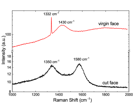
Raman measurements were done on the ”virgin”, i.e. a region of the same sample without any laser treatment, and on the laser cut surfaces of all samples. As example, we show in Fig. 2 the results of the CVD sample #1b. Whereas the virgen surfaces of the samples show a sharp absorption peak at 1332 cm-1 corresponding to pure diamond (first order Raman), the laser-cut surfaces show disordered graphite-like peaks due to the G-band (1580 cm-1) and D-band (1350 cm-1), see Fig. 2. In case of the virgin surfaces, also the peak at 1430 cm-1, observed in CVD samples Stiegler et al. (1996); Badzian and Badzian (1997); Zaitsev (2001), is clearly observed.
We observed some differences in the Raman patterns between the cut surfaces of the CVD ”a” and ”b” samples: whereas in the ”b” samples only Raman peaks corresponding to disordered graphite were observed, the ”a” cut surfaces also showed a weak signal coming from the diamond main Raman peak. Apparently, the polishing procedure transforms the rest of diamond-like regions left after the first laser treatment, leaving only disordered graphite regions. Within the experimentally observed broadening of the Raman peaks, it is not possible to recognize systematic differences between the Raman spectra of the different cut surface orientations. Clearly, Raman characterization helps to identify the presence of graphite-like regions (after the laser treatment) but it does not provide clear hints for the presence of certain defects that can be correlated with the magnetic response.
III.3 Magnetization measurements
III.3.1 Natural diamond samples
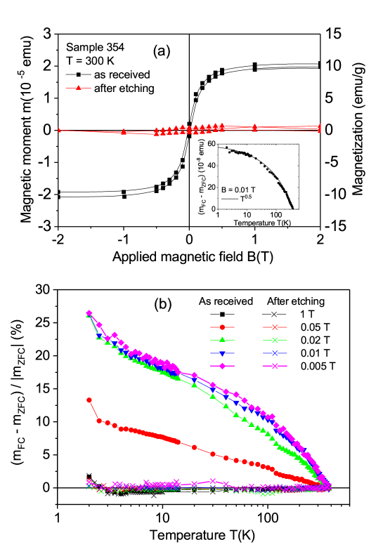
With the magnetic impurity concentration of our samples, the natural diamond crystals in the virgin state (before any laser treatment) do not show any sign of magnetic order at 300 K within the resolution of our SQUID magnetometer ( emu at an applied field of 1 T). Figure 3(a) shows the field hysteresis loops of sample 354 at 300 K before (as-received) and after chemical etching, within T field range. The same diamagnetic linear contribution was subtracted from both data sets. Before chemical etching, the sample shows a clear ferromagnetic response. In the inset of Fig. 3(a) we plot the difference between the field cooled (FC) and zero field cooled (ZFC) states at 0.01 T applied field. This difference follows a temperature dependence similar to that found in irradiated graphite Esquinazi et al. (2010); Spemann and Esquinazi (2016). This similarity and the Raman results, see Section III.2, indicate that the disordered graphite layer produced by the laser treatment should be at the origin of the observed ferromagnetic response. As a proof for this assumption, the same sample was treated chemically to remove the disordered graphitic layer. The reduction of the ferromagnetic response observed in the field hysteresis loop of Fig. 3(a) after chemical etching, clearly indicates that the ferromagnetic behavior is related to the graphitic-like layer produced by the laser treatment.
To further demonstrate the large difference in the ferromagnetic response between the cut sample before and after etching, the difference between the FC and ZFC states relative to the value in the ZFC state given by at different applied magnetic fields is shown in Fig. 3(b). In this figure we recognize that whereas this relative difference reaches % (of ) at low temperatures and at fields T in the as-received sample, it remains below 1 % in the whole temperature range and applied fields after etching the sample. These results indicate further that those signals are related to the surface near graphitic-like region.
With the estimate ferromagnetic thickness of nm and the measured area of the laser cut surface, we obtain a magnetization (right y-axis in Fig. 3(a)) at saturation of 10 emu/g. A comparison with the values of the magnetization at saturation obtained for ferromagnetic graphite Ohldag et al. (2010); Spemann and Esquinazi (2016), we note that this ferromagnetic thickness should be of the order or even smaller.
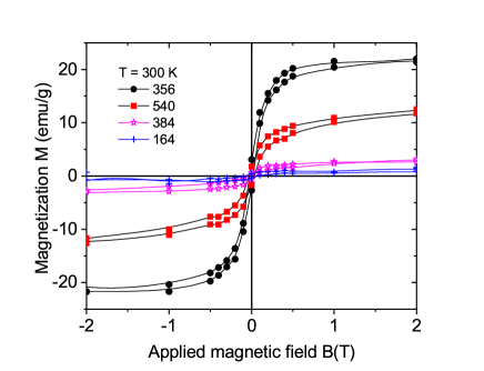
Figure 4 shows the field hysteresis loops of four natural diamond samples with cut areas with orientation (100) (356 and 540, similar to sample 354, see Table 1) and with (111) orientation (164 and 384) at 300 K. Taking into account the cut area and assuming the same ferromagnetic thickness, we recognize that the ferromagnetic signals are clearly smaller for the (111) cut surface samples. This difference is not related to large differences in the assumed ferromagnetic mass because the cut surfaces are similar or their difference shifts the estimate value of magnetization in the opposite direction, see Table 1. This result indicates that the diamond crystalline structure and the laser cut direction relative to its structure play an important role to trigger the ferromagnetic order in the graphitic-like surface layer. The results obtained from the CVD samples support this conclusion, see Section III.3.2.
Nitrogen doping with the concentrations measured in our samples, or lower, see Table 1, does not trigger ferromagnetic order at room temperature.The ferromagnetic signal is not related to the total N-concentration or to the concentration of three defect centers one finds in bulk N-doped diamond (A, B, C), see Figs. 5(a) and (b). In Figs. 5(a) and (b) and due to the fact that these centers are distributed all over the samples, the shown magnetization values were obtained taking into account the whole sample mass. On the other hand, we note that N-related C-centers are at the origin of the clear hysteretic behavior in field and temperature observed below 50 K Barzola-Quiquia et al. (2019); Setzer et al. (2021).
III.3.2 CVD diamond samples
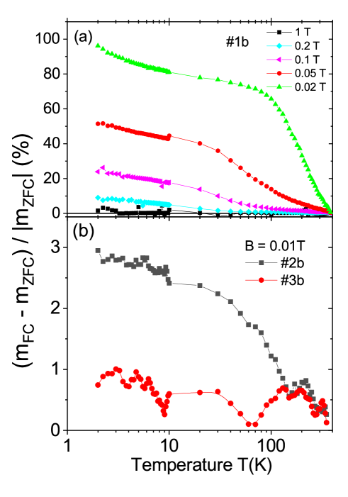
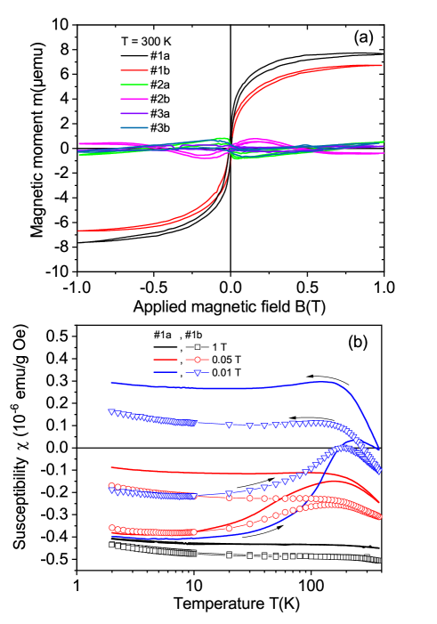
Figure 6(a) shows the field hysteresis loops measured at 300 K of all CVD samples, see Table 2, after subtracting the linear diamagnetic background. The results indicate a ferromagnetic behavior with a coercive fields of the order of 80 Oe for samples #1a and #1b. The magnetic moment at saturation is much smaller for the samples with other crystal orientations. Taking into account the volume of the cut surface or the total mass, the obtained ferromagnetic magnetization of samples #1a and #1b is always larger than that of the other CVD samples, supporting the orientational dependence of the ferromagnetic signals of the laser cut surface observed in the natural diamond crystals. As in the natural diamond crystals, the samples cut with orientation other than the (100) show a much smaller or negligible ferromagnetic signal, see Fig.7. The relative difference between the FC and ZFC curves is nearly two orders of magnitude larger for samples with (100) cut surfaces.
We observe that the saturation magnetic moment of sample #1b obtained after laser polishing the cut surface, is about 10% smaller than of sample #1a. The ferromagnetic behavior is clearly observed in the difference between ZFC and FC states, as shown by the temperature dependence of the susceptibility, see Fig. 6(b). As expected for a ferromagnetic behavior, the difference between ZFC and FC states as a function of temperature vanishes at high magnetic fields, in agreement with the vanishing of the field hysteresis width at high enough fields, see Fig. 6(a).
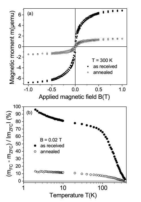
It is known that high temperature annealing in air removes any graphitic-like surface regions in diamond. Therefore, instead of using chemical etching to remove the graphitic surface of the CVD samples, as done in the natural diamond samples (see Fig. 3), we have annealed one of the CVD samples (#1b) in air. The annealing procedure in air was 1h at 550 C, 1h at 600 C and 0.5h at 650 C. Similarly to the result after chemical etching of a natural diamond sample, the ferromagnetic signal strongly decreased after annealing, see Fig. 8. All these results clearly indicate that the ferromagnetic signal comes from the disordered graphite surface region obtained after the laser cut and it is not related to magnetic impurities.
Before concluding, we would like to remark that the Curie temperature of the ferromagnetic order observed in the laser treated surfaces of diamond with (100) direction, is clearly larger than 380 K. The temperature of 380 K is the turning point temperature at which the FC measurement start. For this reason, the difference is always zero at the turning point temperature. A rough extrapolation of the observed temperature dependence of the magnetic moment to temperatures above 400 K, see for example Figs. 4(b) and 6(b), indicates a Curie temperature between 500 K and 750 K, similar to defect-induced ferromagnetic graphite, see Spemann and Esquinazi (2016) and Refs. therein.
IV Conclusions
Independently of the origin of the diamond sample, natural or CVD, we found that under the selected conditions, the laser pulses produced a robust magnetically ordered graphite film at 300 K in samples cut along the diamond (100) surface orientation. Assuming a maximum thickness of 20 nm for the magnetic layer, the magnetization value at saturation varies from emu/g to 20 emu/g at 300 K, similar to the magnetization values obtained for defect-induced ferromagnetic graphite Ohldag et al. (2010); Spemann and Esquinazi (2016). This magnetic order is clearly weaker or absent in the cases of the other two surface orientations. Further focused experimental characterization but also computer simulations as in Ref. Jeschke et al. (1999), are necessary to find the lattice defects (e.g., C-vacancies, sp2-sp3 or C-H complexes) responsible for the observed ferromagnetism. Laser treatment can in principle be used to create localized magnetic spots of small area on a diamond surface. This phenomenon can be of interest not only for memory devices but also for other rather subtle applications, like using a localized magnetic spot near a nitrogen-carbon vacancy (NV-center) to influence its magneto-optical response, especially to increase its field-sensitivity at certain applied field ranges.
Acknowledgements.
One of the authors (PDE) gratefully acknowledges discussions with M. García (University of Kasel) and T. Lühmann (University of Leipzig). We thank N. Batova (Technological Institute) for the SEM measurements. This research was funded by the DFG under the grant DFG-ES 86/29-1 and DFG-ME 1564/11-1. The work in Russia was partially funded by RFBR and NSFC research project 20-52-53051. The research stay of M.T.G. was supported by the DAAD under the Research Stays for University Academics and Scientists 2021 programme, Nr. 57552334.References
- fun (2016) Basic Physics of Functionalized Graphite, Springer Series in Materials Science 244 (P. Esquinazi (ed.), Springer International Publishing AG Switzerland, 2016).
- Talapatra et al. (2005) S. Talapatra, P. G. Ganesan, T. Kim, R. Vajtai, M. Huang, M. Shina, G. Ramanath, D. Srivastava, S. C. Deevi, and P. M. Ajayan, Phys. Rev. Lett. 95, 097201 (2005).
- Zhang et al. (2017) G. Zhang, T. Samuely, Z. Xu, J. K. Jochum, A. Volodin, S. Zhou, P. W. May, O. Onufriienko, J. Kačmarčík, J. A. Steele, J. Li, J. Vanacken, J. Vacík, P. Szabó, H. Yuan, M. B. J. Roeffaers, D. Cerbu, P. Samuely, J. Hofkens, and V. V. Moshchalkov, ACS Nano 11, 5358 (2017).
- Narayan and Bhaumik (2015) J. Narayan and A. Bhaumik, Journal of Applied Physics 118, 215303 (2015).
- Kenmochi et al. (2004) K. Kenmochi, K. Sato, A. Yanase, and H. Katayama-Yoshida, Japanese Journal of Applied Physics 44, L51 (2004).
- Chan et al. (2004) J. A. Chan, B. Montanari, J. D. Gale, S. M. Bennington, J. W. Taylor, and N. M. Harrison, Phys. Rev. B 70, 041403(R) (2004).
- Kobayashi et al. (2006) Y. Kobayashi, K.-I. Fukui, T. Enoki, and K. Kusakabe, Phys. Rev. B 73, 125415 (2006).
- Ma et al. (2005) Y. Ma, P. O. Lehtinen, A. S. Foster, and R. M. Nieminen, Phys. Rev. B 72, 085451 (2005).
- Saito et al. (2005) T. Saito, T. Ozeki, and K. Terashima, Solid State Commun. 136, 546 (2005).
- Lee et al. (2005) K. W. Lee, Y.-H. Lee, I.-M. Kim, and C. E. Lee, Journal of the Korean Physical Society 47, 337 (2005).
- Ohldag et al. (2010) H. Ohldag, P. Esquinazi, E. Arenholz, D. Spemann, M. Rothermel, A. Setzer, and T. Butz, New Journal of Physics 12, 123012 (2010).
- Makarova et al. (2011) T. L. Makarova, A. L. Shelankov, I. T. Serenkov, V. I. Sakharov, and D. W. Boukhvalov, Phys. Rev. B 83, 085417 (2011).
- Friedman et al. (2010) A. L. Friedman, H. Chun, Y. J. Jung, D. Heiman, E. R. Glaser, and L. Menon, Phys. Rev. B 81, 115461 (2010).
- Yazyev (2016) O. V. Yazyev, “Chap. 1 in basic physics of functionalized graphite,” (P. Esquinazi (ed.), Springer International Publishing AG Switzerland, 2016) pp. 1–24.
- Ohldag (2016) H. Ohldag, “Chap. 2 in basic physics of functionalized graphite,” (P. Esquinazi (ed.), Springer International Publishing AG Switzerland, 2016) pp. 25–44.
- Spemann and Esquinazi (2016) D. Spemann and P. Esquinazi, “Chap. 3 in basic physics of functionalized graphite,” (P. Esquinazi (ed.), Springer International Publishing AG Switzerland, 2016) pp. 45–76.
- García et al. (2012) N. García, P. Esquinazi, J. Barzola-Quiquia, and S. Dusari, New Journal of Physics 14, 053015 (2012).
- Ariskina et al. (2021) R. Ariskina, M. Schnedler, P. D. Esquinazi, A. Champi, M. Stiller, W. Hergert, R. E. Dunin-Borkowski, P. Ebert, T. Venus, and I. Estrela-Lopis, Phys. Rev. Materials 5, 044601 (2021).
- Wang et al. (2000) C. Z. Wang, K. M. Ho, M. D. Shirk, and P. A. Molian, Phys. Rev. Lett. 85, 4092 (2000).
- Jeschke et al. (1999) H. O. Jeschke, M. E. Garcia, and K. H. Bennemann, Phys. Rev. B 60, R3701 (1999).
- Takesada et al. (2003) M. Takesada, E. Vanagas, D. Tuzhilin, I. Kudryashov, S. Suruga, H. Murakami, N. Sarukura, K. Matsuda, S. Mononobe, T. Saiki, M. Yoshimoto, and S. ya Koshihara, Japanese Journal of Applied Physics 42, 4613 (2003).
- Mouhamadali et al. (2020) F. Mouhamadali, S. Equis, F. Saeidi, J. Best, M. Cantoni, P. Hoffmann, and K. Wasmer, Optics and Lasers in Engineering 126, 105917 (2020).
- (23) J.-P. Hermani, M. Emonts, and C. Brecher. Nanosecond Laser Processing of Diamond Materials, in Lasers in Manufacturing Conference 2015, https://www.wlt.de/lim/Proceedings2015/Stick/PDF/ Contribution299_final.pdf
- Sasaki et al. (2012) Y. Sasaki, A. Takeda, Kiyoto, S. Ohshio, H. Akasaka, M. Nakano, and H. Saitoh, Diamond & Related Materials 24, 104 (2012).
- Polushin et al. (2018) N. I. Polushin, M. S. Ovchinnikova, and M. N. Sorokin, Russian Journal of Non-Ferrous Metals 59, 557 (2018).
- Babich and Feigelson (2009) Y. Babich and B. Feigelson, Inorg Mater 45, 616 (2009).
- Woods (1984) G. S. Woods, Philosophical Magazine B 50, 673 (1984).
- Stiegler et al. (1996) J. Stiegler, Y. von Kaenel, M. Cans, and E. Blank, Journal of Materials Research 11, 716–726 (1996).
- Badzian and Badzian (1997) A. Badzian and T. Badzian, International Journal of Refractory Metals and Hard Materials 15, 3 (1997), wear Resistant Materials for the South African Industry.
- Zaitsev (2001) A. Zaitsev, Optical Properties of Diamond (Springer Berlin Heidelberg, 2001).
- Esquinazi et al. (2010) P. Esquinazi, J. Barzola-Quiquia, D. Spemann, M. Rothermel, H. Ohldag, N. García, A. Setzer, and T. Butz, J. Magn. Magn. Mat. 322, 1156 (2010).
- Barzola-Quiquia et al. (2019) J. Barzola-Quiquia, M. Stiller, P. Esquinazi, A. Molle, R. Wunderlich, S. Pezzagna, J. Meijer, W. Kossack, and S. Buga, Scientific Reports 9, 8743 (2019).
- Setzer et al. (2021) A. Setzer, P. D. Esquinazi, O. Daikos, T. Scherzer, A. Pöppl, R. Staacke, T. Lühmann, S. Pezzagna, W. Knolle, S. Buga, B. Abel, and J. Meijer, physica status solidi (b) 258, 2100395 (2021).