Anisotropic topological superconductivity in Josephson junctions
Abstract
We investigate the effects of magnetic and crystalline anisotropies on the topological superconducting state of planar Josephson junctions (JJs). In junctions where only Rashba spin-orbit coupling (SOC) is present, the topological phase diagram is insensitive to the supercurrent direction, but exhibits a strong dependence on the magnetic field orientation. However, when both Rashba and Dresselhaus SOCs coexist, the topological phase diagram strongly depends on both the magnetic field and junction crystallographic orientations. We examine the impact of the magnetic and crystalline anisotropy on the current-phase relation (CPR), energy spectrum, and topological gap of phase-biased JJs, where the junction is connected in a loop and the superconducting phase difference is fixed by a loop-threading magnetic flux. The anisotropic CPR can be used to extract the ground-sate phase (i.e. the superconducting phase difference that minimizes the system free energy) behavior in phase-unbiased JJs with no magnetic flux. Under appropriate conditions, phase-unbiased JJs can self-tune into or out of the topological superconducting state by rotating the in-plane magnetic field. The magnetic field orientations at which topological transitions occur strongly depend on both the junction crystallographic orientation and the relative strength between Rashba and Dresselhaus SOCs. We find that for an optimal practical application, in which the junction exhibits topological superconductivity with a sizable topological gap, a careful balancing of the magnetic field direction, the junction crystallographic orientation, and the relative strengths of the Rashba and Dresselhaus SOCs is required. We discuss the considerations that must be undertaken to achieve this balancing for various junction types and parameters.
I Introduction
Majorana bound states (MBSs) are zero-energy quasiparticle excitations predicted to arise in topological superconductors (TSs). [1, 2, 3, 4, 5, 6] Due to their non-Abelian exchange statistics they can be utilized as qubits for fault-tolerant quantum computing, with quantum gates realized through braiding operations. [7, 8, 9, 10] Driven by this technological impetus, proposals to achieve topological superconductivity have included, among others, 1D systems such as magnetic chains on s-wave superconductors, [11, 12, 13, 14, 15, 16] semiconductor nanowires with large spin-orbit coupling (SOC) proximitized by s-wave superconductors, [17, 18, 19, 20, 21, 22, 23, 24, 25, 26, 27] and proximitized systems exposed to magnetic textures. [28, 29, 30, 31, 32, 33, 34, 35, 36] Because of their experimental feasibility, planar Josephson junctions (JJs) have also been considered as an alternative promising platform for creating and manipulating MBSs. [37, 38, 39, 40, 41, 42, 43, 44, 45, 46, 47, 48, 49, 50, 51, 52, 53, 54, 55, 56, 57, 58, 59, 60, 61, 62] Moreover, the superconducting phase difference across JJs provides an additional control knob that can enhance the parameter space leading to topological superconductivity. However, tuning a planar JJ to a topologically nontrivial state does not necessarily guarantee the existence of a sizable topological gap, which is a practical requirement for the stability of MBSs and braiding operations. [63, 64] Indeed, as shown later in this work (see also Ref. 65), even when the parameter space for topological superconductivity is relatively large, the topological gap may be sizable only over reduced subregions.
Josephson junctions with noncentrosymmetric superconductors (particularly -wave superconductors) have been predicted to exhibit anisotropic effects. [66, 67, 68] In this work, we consider the effects of magnetic and crystalline anisotropies on the topological superconducting state in planar JJs formed in a semiconducting two-dimensional electron gas proximitized by -wave superconductors. The interrelation between the Zeeman interaction and the Rashba SOC emerging from the lack of structure inversion symmetry [69] in proximitized planar JJs gives rise to a strong dependence of the system properties on the magnetic field direction. Furthermore, in junctions where both Rashba and Dresselhaus SOCs are relevant, not only the magnetic field direction, but also the junction crystallographic orientation can strongly affect the topological superconducting state. [65] The Dresselhaus SOC originates from the bulk inversion asymmetry, [70] which can be particularly large in some zinc blende semiconductors (e.g., InSb) suitable for building superconductor/semiconductor proximitized JJs. [71] Here we investigate the impact of SOC-induced anisotropies of topological phase transitions on the topological gap, topological charge, energy spectrum, ground-state phase, current phase relation, and critical currents in planar JJs.
II Theoretical Model
II.1 General considerations
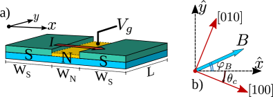
We consider JJs composed of superconducting (S) and normal (N) regions (see Fig. 1). The S regions are formed in a semiconducting 2DEG proximitized by a superconducting (e.g., Al or Nb) covering. Excitations in the JJ are described by the Bogoliubov-de Gennes (BdG) Hamiltonian,
| (1) |
where
is the single-particle Hamiltonian of the 2DEG in the absence of a magnetic field. In the equations above, is the momentum, the electron effective mass, and are, respectively, the Rashba and Dresselhaus SOC strengths, and characterizes the direction of the current ( axis) with respect to the [100] crystallographic direction of the semiconductor [Fig. 1(b)]. The crystallographic orientation of the junction is determined by the angle . The length of the junction is and the widths of the S and N regions are and , respectively (see Fig. 1). The gate-voltage-induced difference between the chemical potentials in the N () and S () regions is described by and and , with , represent Pauli and Nambu matrices, respectively. The chemical potentials are measured with respect to the minimum of the single-particle energies, , where we have used the SOC parametrization,
| (3) |
Here represents the overall strength of the combined Rashba + Dresselhaus SOCs, while the spin-orbit angle,
| (4) |
characterizes the relative strength between Rashba and Dresselhaus SOC.
The second contribution in Eq. (1), with the Dirac spin matrices , represents the Zeeman splitting due to an applied magnetic field,
| (5) |
The angle characterizes the direction of the magnetic field with respect to the current flow ( axis), as shown in Fig. 1(b). The spatial dependence of the superconducting gap is , where is the phase difference across the JJ.
The temperature and magnetic field dependence of the superconducting gap is taken into account by using the BCS relation,
| (6) |
where , , is the Boltzmann constant, and is the superconductor critical temperature. The temperature dependence of the critical magnetic field can be approximated as, , where is the critical magnetic field at zero temperature.
Although we consider ballistic junctions throughout this work, we expect the predicted anisotropic effects to qualitatively hold in the presence of weak disorder. Junctions with low disorder are usually preferred because the presence of disorder typically reduces the parameter space supporting topological superconductivity, although in some cases weak disorder can increase the robustness of the topological superconducting state [73, 74, 75, 76].
II.2 Topological gap and topological charge
Topological superconductivity (TS) is a superconducting phase featuring a pair of degenerate zero-energy states, called Majorana bound states (MBSs), which are isolated from the rest of the excitation spectrum by an energy gap, called the topological gap (). In the TS state, the topological gap cannot be destroyed by smooth local perturbations, providing protection for the MBSs. However, the information stored in the MBSs can be damaged if the perturbation energy becomes comparable or larger than the topological gap. A large topological gap is therefore desirable for the practical use of fault-tolerant qubits encoded in MBSs.
The topological gap can be estimated by imposing translational invariance along the junction direction (the direction in our case). In such a system, the momentum component is a conserved quantity and can be substituted by . Then is obtained as the eigenenergy closest to zero,
| (7) |
only when the system is in the TS state. When the system is in the trivial state, the quantity defined in Eq. (7) simply denotes the lowest positive-energy Andreev state.
The size of the topological gap strongly depends on the interrelation between the spin-orbit angle (), the junction crystallographic orientation () and the in-plane magnetic field orientation (). [48, 65] In symmetric JJs (i.e., with identical left and right S coverings) the optimal topological gap is achieved when the system is in the TS state and the condition, [65]
| (8) |
is fulfilled.
This work focuses on the behavior of the current across the JJ (see Fig. 1a). Hence, we use the current direction as the axis with respect to which the magnetic field orientation, , is defined (see Fig. 1b) [77].
In the presence of Rashba and Dresselhauss SOC the topological gap exhibits strong magnetic and crystalline anisotropies. [65] Therefore the fulfillment of Eq. (8) is a vital prerequisite for the optimization of . However, the relation in Eq. (8) alone is not sufficient for inducing TS. Therefore, in a practical situation, one will need to first arrange the experimental setup in a way that Eq. (8) is fulfilled, and then tune other system parameters (e.g., chemical potential, magnetic field amplitude) to drive the system into the TS state.
The TS state in symmetric JJs typically belongs to the D class. However, the BDI class can emerge for some specific junction crystallographic orientations and magnetic field directions (see Table I in Ref. 65). Therefore, the transition between the trivial and TS states typically occur when the topological index (also called topological charge, ) associated with the symmetry class D changes sign. According to the bulk-boundary correspondence, we can obtain the phase diagram of a junction with finite length by computing the topological charge of the translational-invariant version of the junction,
| (9) |
where denotes the Pfaffian [78, 79, 80, 81]. The topological charge determines whether the system is in the trivial () or topological () phase. [82, 83, 73, 74, 75, 84]
II.3 Current-phase relation and critical current in Josephson junctions
The supercurrent across the JJ can be obtained from the energy spectrum of the BdG Hamiltonian given in Eq. (1). Indeed, the eigenenergies () can be used to compute the free energy of the junction,
| (10) |
with . The current-phase relation (CPR) is then obtained as
| (11) |
where the zero-temperature contribution is given by
| (12) |
while the temperature-dependent correction reads,
| (13) |
In the low-temperature limit (), Eqs. (11)–(13) yield
| (14) | |||||
while in the high-temperature regime (),
| (15) |
In the phase-biased case, the JJ is connected to a closed loop threaded by a magnetic flux, , and the superconducting phase difference across the junction is fixed to the value , where is the magnetic flux quantum. In this case the current-phase relation [Eq. 11] can be experimentally measured by tuning the magnetic flux.
In the absence of a magnetic flux the junction is phase unbiased and the phase difference self-adjusts in such a way that the free energy of the system is minimized. The ground-state phase () is the superconducting phase difference that minimizes the free energy of the system, i.e.,
| (16) |
and the ground-state spectrum is the energy spectrum of the JJ evaluated at the ground-state phase, i.e., . The mathematical conditions for the free energy to have a minimum at the ground-state phase are,
| (17) |
which, according to Eq. (11) can be rewritten as,
| (18) |
The relations above allow for extracting the ground-state phase from the CPR.
Under forward bias voltage, the critical current of a phase-unbiased JJ is obtained by maximizing the current amplitude with respect to the phase difference, i.e.,
| (19) |
However, under reverse bias voltage, the critical current is negative and is determined by minimizing the supercurrent. In centrosymmetric JJs the amplitudes of the forward and reverse critical currents are equal. However, the interrelation between the SOC and the in-plane magnetic field can break the inversion symmetry and lead to the so-called superconducting diode effect [85, 86, 87, 88, 89, 90, 91], where the amplitudes of the forward and reverse critical currents become different. In this work we limit our analysis to the case of the forward critical current.
II.4 Numerical Approach
We use a finite-difference discretization of Eq. (1) to build a tight-binding version of the BdG Hamitonian, which is then numerically diagonalized to find the eigenstates and energy spectrum (see Appendix A for more details). The Pfaffians of the tight-binding Hamiltonian with imposed translational invariance along the junction direction are numerically calculated to compute the topological charge, while the energy spectrum is used to calculate the free energy of the system, CPR, ground state phase, and critical currents.
The numerical simulations of the tight-binding version of the BdG Hamiltonian are performed by using the Kwant package [92]. To illustrate and compare the different effects of magnetic and crystalline anisotropies, two type of junctions are considered: i) Al/HgTe JJs, where only Rashba SOC plays a role and ii) Al/InSb JJs, where both Rashba and Dresselhaus SOC become relevant (see Appendix for more details).
III Current-phase relation in phase-biased Josephson junctions
III.1 Effects of magnetoanisotropy
To investigate the effects of magnetic field orientation on the CPR of a phase-biased JJ, we consider Al/HgTe JJs (see system parameters in Appendix A), where Rashba SOC is large and Dresselhaus SOC is negligibly small. In such systems the spin-orbit angle and the CPR is independent of the junction crystallographic orientation. For the chosen system parameters, the estimated zero-field superconducting coherence length of the Al/HgTe JJ is nm, which is smaller but comparable to the width of the normal region, and about 1/4th the size of each lead.
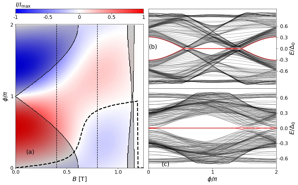
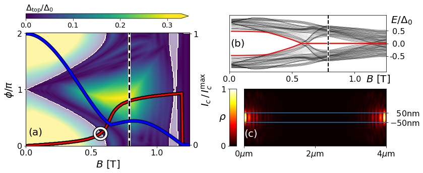
The supercurrent (normalized to its maximum value) of a Al/HgTe JJ is shown in Fig. 2(a) as a function of an in-plane magnetic field perpendicular to the current (i.e., ) and the superconducting phase difference. The shaded (unshaded) areas correspond to topological charge (trivial state) and (TS state), respectively. Both the supercurrent amplitude and direction can be tuned by changing the phase difference and/or the magnetic field strength. Note that for magnetic fields larger than the critical field (1.19 T at 0.7 K), superconductivity is destroyed and the supercurrent vanishes.
At zero magnetic field the CPR is anti-symmetric under reflection with respect to , i.e., . In the presence of Rashba SOC and a finite in-plane magnetic field this symmetry is preserved only when the field is parallel to the current (). The symmetry breaking for and is clearly seen in Fig. 2(a).
The two white traces in Fig. 2(a) correspond to parameters for which the supercurrent vanishes. However, the conditions in Eq. (18) are satisfied only along the lower trace. As shown in the figure, the path of the lower trace is in good agreement with the magnetic field dependence of the ground-state phase (black dashed line). This illustrates how the magnetic field dependence of the CPR in a phase-biased junction can be used to extract the ground-state phase of the phase-unbiased junction. The method works well when only a single trace in the dependence of the CPR satisfies Eq. (18). However, the situation may not be that clear when there are multiple traces obeying Eq. (18). In such a case, different traces correspond to different free energy minima, and the information in the dependence of the CPR is not enough to decide which one represents the absolute minimum.
The phase dependence of the energy spectrum is shown in Figs. 2(b) and 2(c) for T and T [indicated with vertical dashed lines in (a)], respectively. The red lines illustrate the formation of MBSs in the TS state. For T, zero-energy MBSs appear in a reduced interval of -values, while at T zero-energy MBSs exist for any value of the phase difference. This is an agreement with the topological region depicted in Figs. 2(a). Although the junction is long enough, and the MBSs are typically well separated from each other [note that MBSs have zero energy in most of the topological region, as shown in Figs. 2 (b) and (c)], they start to hybridize and depart from zero energy when the topological gap becomes too small. This is particularly noticeable in Fig. 2(c) around , and emphasizes the fact that, even if the system is in the topological state, one may still need to optimize the topological gap to realize stable MBSs.
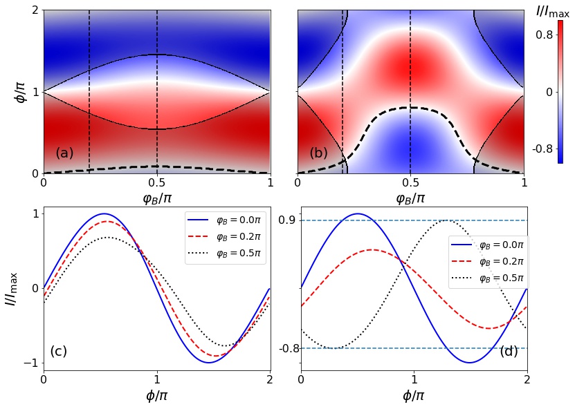
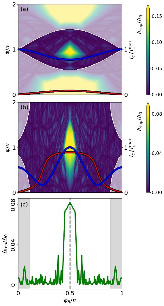
The Rashba SOC is rotationally invariant, however its combination with the in-plane Zeeman interaction leads to magnetoanisotropic effects. The magnetic anisotropy of the CPR is shown if Figs. 3(a) and 3(b), where the normalized supercurrent is shown as a function of the phase difference, , and the magnetic field orientation, for the two values of magnetic field amplitudes corresponding to the vertical dashed lines in Fig. 2(a). In both cases, the topological region exhibits a strong dependence on . When the in-plane magnetic field is parallel to the supercurrent direction, the system is in the trivial state for any phase difference. As the magnetic field is rotated towards the junction direction, the range of phase differences leading to TS increases. The results demonstrate the convenience of orienting the magnetic field in the direction, , i.e., perpendicular to the supercurrent flow. [48, 65] The CPR at different magnetic field orientations indicated by vertical dashed lines in Figs. 3(a) and 3(b) are shown in Figs. 3(c) and 3(d), respectively. In both cases, the CPR shows a slight deviation from a sinusoidal function, evidencing the low transparency of the junction. Furthermore, an anomalous phase [93, 94, 90, 95, 51, 87] emerges due to the combined action of the Rashba SOC and the in-plane magnetic field, producing a -dependent shift of the CPR. Although hardly notable at the scale of the figure, numerical evaluation reveals that for , the forward (maximum) and reverse (minimum) supercurrents are slightly different. This manifestation of the superconducting spin diode effect[89] is perhaps more apparent in the CPR shown in Fig. 3(d) for T and , where the horizontal lines indicate the different amplitudes of the forward and reverse supercurrents.
III.2 Effects of crystalline anisotropy
The linear Rashba SOC exhibits rotational invariance. However, the coexistence of Rashba and Dresselhaus SOCs reduce the symmetry of the spin-orbit field to a twofold symmetry [96, 97]. Such a symmetry reduction leads to various magnetoanisotropic phenomena in both the normal [98, 99, 100, 101] and superconducting [102, 103, 104, 105, 106, 107] states as well as crystalline anisotropic phenomena in which the system properties depend on the specific crystallographic orientation and/or transport direction [108, 65, 109]. The effects of crystalline anisotropy on the topological gap of planar JJs was investigated in Ref. 65. In this Section we explore the SOC-induced crystalline anisotropy of the CPR in a phase-biased, planar JJ. For the numerical simulations of the crystalline anisotropy, we consider Al/InSb JJs, which for the considered system parameters (see Appendix A) have an estimated zero-field superconducting coherence length, nm, which is larger than , but shorter than .
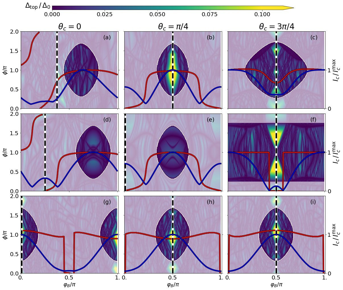
The CPR as a function of the in-plane magnetic field direction is shown in Fig. 4 for different supercurrent directions () and spin-orbit angles (). The supercurrent direction is fixed by the junction orientation with respect to the crystallographic axis. The dashed lines indicate the ground-state phase computed by minimizing the system free energy and are in good agreement with the CPR contours obeying Eq. (18). When only Rashba SOC is present, and the CPR is independent of . However, the presence of Dresselhaus SOC leads to appreciable changes in the CPR. For , the topological (unshaded) region changes its size and exhibits a shift in its position with respect to the magnetic field direction when the supercurrent direction changes, as shown in Figs. 4(a)–4(c). A similar trend is observed when the strength of the Rashba and Dresselahus SOC are equal, [i.e., in Figs. 4(d) and 4(e)] and when only Dresselhaus SOC is present [i.e., in Figs. 4(g)–4(i)].
Previous investigations [37, 39, 42] have shown the importance of properly tuning the
chemical potential, magnetic field strength, and superconducting phase
difference for driving the JJ into the TS state. However, the strong
dependence of the TS state and the ground-state phase on the spin-orbit
angle (), the magnetic field orientation (),
and the supercurrent direction (), shown in
Fig. 4, reveals that an
experimental setup with an adequate combination of ,
, and values is also crucial for inducing TS in
planar JJs.
IV Topological superconductivity in phase-unbiased Josephson junctions
IV.1 Effects of magnetoanisotropy
In the absence of a magnetic flux, the superconducting phase difference self-tunes to a value (the ground-state phase, ) that leads to the minimization of the system free energy. Since the free energy of the junction varies with the applied magnetic field, both the ground-state phase and the critical current also change as the strength of the in-plane magnetic field increases.
The topological gap [see Eq. (7)] of a HgTe JJ (where only Rashba SOC is relevant) with an in-plane magnetic field perpendicular to the supercurrent direction is shown in Fig. 5(a) as a function of the phase difference and magnetic field amplitude. The shaded and unshaded regions correspond to trivial () and topological () phases. The red and blue lines correspond to the ground-state phase and normalized critical current, respectively. The ground-state phase exhibits a jump from 0 to as the magnetic field increases, as shown in Fig. 5(a) and earlier in Fig. 2(a). The junction transitions into the topological state at the center of the white ring, where crosses the topological region. The ground-state phase jump is accompanied by a local minimum in the critical current (blue line). However, due to the smoothness of the ground-state jump, the critical current minimum may occur at a magnetic field higher than the transition field (corresponding to the center of the white ring). Therefore, in the best situation, the critical current minimum alone can only be an indirect indication of the topological phase transition. In a more general scenario, there are situations in which the topological transition occurs without the current having a local minimum [110, 39].
Figure 5(a) reveals that the topological gap is sizable only on a reduced part of the topological region. The topological gap is crucial for ensuring the practical protection of the MBSs. Therefore, only the portion of the parameter space leading to the TS state with a sizable topological gap is useful from a practical point of view. The departure of from the value 0 as the magnetic field increases, yields a topological transition at a magnetic field slightly smaller than the one required at . Furthermore, the self-tuned jump of the ground-state phase to values close to allows for achieving a sizable topological gap in the TS state.
The ground-state spectrum, i.e., the energy spectrum for which the junction has the minimum free energy, is shown in Fig. 5(b) as a function of the magnetic field strength. At zero magnetic field the system is in the trivial state with a gap of about . As the magnetic field increases, the ground-state phase starts to depart from zero, yielding a decrease in the energy gap until it closes and reopens at the topological transition. Once the system enters the TS state, zero energy MBSs (red line) emerge inside the topological gap. The probability density of the MBSs (normalized to its maximum value) is shown in Fig. 5(c) for a magnetic field value indicated by the vertical dashed line in (b). The MBSs are well localized at the ends of the junction.
The magnetic anisotropy of the topological gap, the ground-state phase (red line), and the critical current is shown in Fig. 6(a) for T. The trajectory of the ground-state phase indicates that for such a field value the system is unable to self-tune into the TS state for any magnetic field orientation. The critical current (blue line) exhibits a local minimum but it is not associated to a topological transition. However, if the field amplitude is increased to 1 T, the self-tuning of the ground-state phase can drive the system into the TS state when the magnetic field is rotated away from the direction of the supercurrent, as shown in Fig. 6(b). In this case, the jump in the ground-state phase not only allows for the topological transition, but also for a finite topological gap when . The jumps in the ground-state phase are accompanied by critical current minima. Interestingly, the critical current exhibits a maximum at the magnetic orientation leading to the TS state with the largest topological gap.
The ground-state topological gap (i.e., the topological gap at the ground-state phase) as a function of the magnetic field orientation for a phase-unbiased Al/HgTe JJ is represented by the green line in Fig. 6(c). As the in-plane magnetic field is rotated from a direction parallel () to perpendicular () to the supercurrent direction, the topological gap self-tunes from a negligible small value to a maximum of about . The figure illustrates the importance of properly orienting the magnetic field when driving the system into a robust TS state, and evidences that even if the ground-state phase self-tuning can drive the system in the TS state for a wide range of magnetic field orientations (white area), the topological gap is sizable and stable only within a small window around . This is consistent with recent experimental results, where the TS state deteriorates as the magnetic field deviates from the direction perpendicular to the supercurrent. [42]
IV.2 Effects of crystalline anisotropy
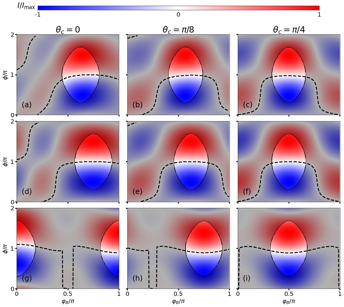
To explore the effects of crystalline anisotropy on phase-unbiased JJs, we consider an Al/InSb junction (see Appendix A for system parameters), where Rashba and Dresselhaus SOCs coexist. The topological gap as a function of the magnetic field orientation is shown in Fig. 7 for T, different crystallographic orientations () of the junction, and various values of the spin-orbit angle (). The top row corresponds to , i.e., to a situation in which Rashba SOC is about 2.4 times stronger than Dresselhaus SOC. The middle row displays the case , in which Rashba and Dressellhaus SOCs have equal strength, and the bottom row with corresponds to a junction in which only Dresselhaus SOC is present. The case of junctions in which only Rashba SOC is present has been omitted because such junctions do not exhibit crystalline anisotropy. Shaded and unshaded regions represent trivial () and topological () states, respectively. The blue lines represent the normalized positive branch of the critical current, while the red lines indicate the ground-state phase behavior. The topological regions, critical current, and ground-state phase exhibit a strong dependence on both the magnetic field and junction orientations. Furthermore, the critical current dependence on the magnetic field direction can be used to determine whether both Rashba and Dresselhaus or only one SOC interaction is present in the system. Indeed, as long as the junction is not oriented along the spin-orbit field symmetry axes [i.e., ] and only Rashba, only Dresselhaus, or both SOCs are present, the absolute maxima of the critical current occur for magnetic field orientations [see Fig. 6(b)], [see Fig. 7(g)], or (with being an integer number) [see Figs. 7(a) and 7(d)], respectively.
The spin-orbit field in zinc-blende semiconductor quantum wells grown along the crystallographic direction exhibits a symmetry, with symmetry axes along the and directions. [97] Although the specific crystallographic direction of the junction may lower the symmetry to , the symmetry is still preserved as long as the junction direction coincides with one of the spin-orbit field symmetry axes (i.e., when , with being an integer number). This is the situation in the middle and right columns in Figs. 7, where the topological gap, ground-state phase, and critical current exhibit a symmetry with respect to the magnetic field orientation with a symmetry axis . Note that for and , corresponds to magnetic fields along the and directions, respectively (i.e., to magnetic field directions along symmetry axes of the spin-orbit field).
Unlike the critical current dependence on the magnetic field strength, which may exhibit minima (accompanied by ground-state phase jumps) when the system transits from the trivial to the topological superconducting state [37, 42] (see also Fig. 8), the minima of the critical current dependence on the magnetic field direction (see Fig. 7) is not an indicator of topological phase transitions.
The results shown in Fig. 7 reveal that the realization of the topological superconducting state with a sizable topological gap requires an adequate orientation of the magnetic field, according to the junction crystallographic direction. Indeed, even if the system is in the topological state, the topological gap protecting the MBSs can be very small when the optimal magnetic field orientation (vertical, dashed lines) calculated from Eq. (8) do not cross the topological region, as shown in Figs. 7(a), 7(d), and 7(e). However, a sizable topological gap is achieved when the system is in the TS state and the magnetic field orientation fulfills Eq.(8), as illustrated in Figs. 7(b), 7(c), and 7(f)–7(i).
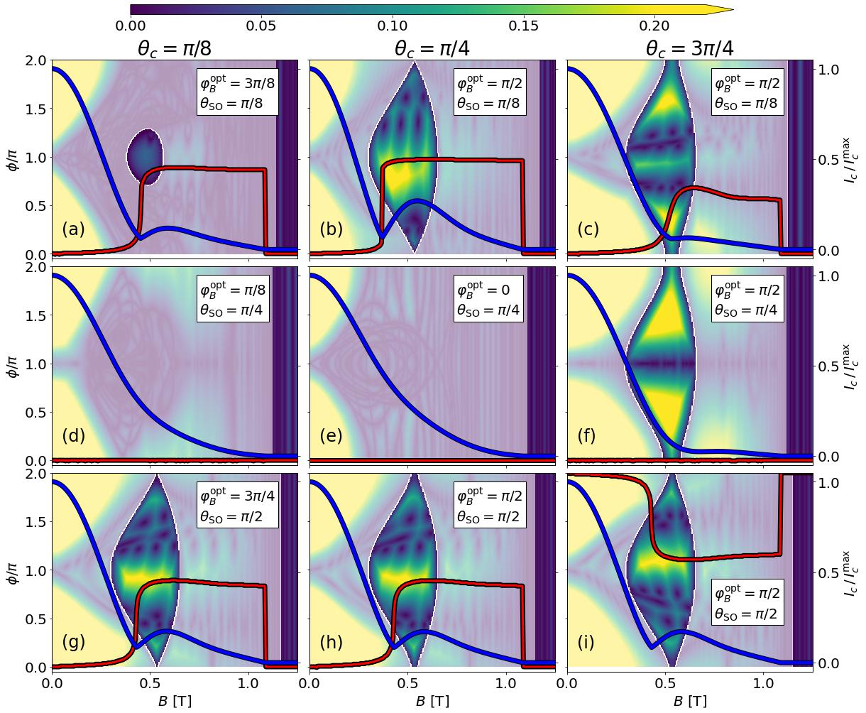
The topological gap as a function of the magnetic field strength is shown in Fig. 8 for for the corresponding optimal magnetic field orientations (), different crystallographic orientations () of the junction, and various values of the spin-orbit angle (). For and (upper and lower rows, respectively), as the magnetic field strength is increased, the system transits into the TS state when the ground-state phase (red line) jumps and crosses into the topological region (unshaded zones). The proper orientation of the magnetic field allows for the existence of a sizable topological gap when the system enters in the TS state. The jump of the ground-state phase is accompanied by a minimum in the critical current. Such a behavior has previously been used as a signature of TS phase transitions. [37, 42] Note, however, that in junctions with narrow S regions critical current minima may not necessarily signal topological transitions [38, 110] and the observation of more reliable signatures in other physical quantities, such as the spin susceptibility might be required [110]. When the Rashba and Dresselhaus SOCs have equal strengths (i.e., ) and or , the system remains in the trivial state for all magnetic field strengths and no ground-state jump nor local critical current minimum occur. However, the system can still reach the TS state when , even without a ground-state phase jump (nor associated critical current minimum). However, the absence of the phase jump does not allow the system to reach the TS state with an optimal topological gap. The results suggest that coexisting Rashba and Dresselhaus SOCs with equal strength may not be favorable for realizing stable TS in phase-unbiased JJs.
V Summary
We show that a rich interplay of magnetic field direction, crystalline orientation, and the relative strengths between Rashba and Dresselhaus SOCs (parametrized by a spin-orbit angle), all play an important role in defining the optimal set of parameters that lead to a large topological gap in a topologically nontrivial state. We provide examples of the effects of magnetoanisotropy on the current-phase relation of a proximitized Al/HgTe planar JJ, where only Rashba SOC is sizable, and show that both the topological phase diagram and the CPR strongly depend on the direction of the applied magnetic field. We demonstrate that for a phase-unbiased planar JJ in which the phase is allowed to self-tune to its ground-state value (i.e., the phase value that minimizes the system free energy), changing the magnetic field direction can cause -jumps in the ground-state phase. We also consider the case of an Al/InSb junction, where both Rashba and Dresselhaus SOCs are relevant and not only the magnetic field direction, but the junction crystallographic orientation and spin-orbit angle also affect the topological superconducting state. We show that to realize stable MBSs, the system parameters must be tuned such that the junction is in the topological superconducting state and a sizable topological gap is achieved by properly orienting the magnetic field, in dependence of the junction crystallographic orientation and the spin-orbit angle parametraizing the relative strengths between Rashba and Dresselhaus SOCs. In phase-unbiased JJs the ground-state phase self-tunes and can exhibit -jumps as the magnetic field is rotated. When the magnetic field orientation is optimal and the field strength is varied, the ground-state selftuning -jumps enables the system transition to the topological superconducting state with a sizable topological gap.
Acknowledgments. This work was supported by DARPA Grant No. DP18AP900007.
References
- Kitaev [2001] A. Y. Kitaev, Phys.-Usp. 44, 131 (2001).
- Kitaev [2003] A. Kitaev, Ann. Phys. 303, 2 (2003).
- Leijnse and Flensberg [2012] M. Leijnse and K. Flensberg, Semicond. Sci. and Technol. 27, 124003 (2012).
- Beenakker [2013] C. Beenakker, Annu. Rev. Condens. Matter Phys. 4, 113 (2013).
- Aguado [2017] R. Aguado, Riv. Nuovo Cimento 40, 523 (2017).
- Qi and Zhang [2011] X.-L. Qi and S.-C. Zhang, Rev. Mod. Phys. 83, 1057 (2011).
- Ivanov [2001] D. A. Ivanov, Phys. Rev. Lett. 86, 268 (2001).
- Nayak et al. [2008] C. Nayak, S. H. Simon, A. Stern, M. Freedman, and S. Das Sarma, Rev. Mod. Phys. 80, 1083 (2008).
- Alicea et al. [2011] J. Alicea, Y. Oreg, G. Refael, F. von Oppen, and M. P. A. Fisher, Nature Phys. 7, 412 (2011).
- Aasen et al. [2016] D. Aasen, M. Hell, R. V. Mishmash, A. Higginbotham, J. Danon, M. Leijnse, T. S. Jespersen, J. A. Folk, C. M. Marcus, K. Flensberg, and J. Alicea, Phys. Rev. X 6, 031016 (2016).
- Choy et al. [2011] T.-P. Choy, J. M. Edge, A. R. Akhmerov, and C. W. J. Beenakker, Phys. Rev. B 84, 195442 (2011).
- Martin and Morpurgo [2012] I. Martin and A. F. Morpurgo, Phys. Rev. B 85, 144505 (2012).
- Pientka et al. [2013] F. Pientka, L. I. Glazman, and F. von Oppen, Phys. Rev. B 88, 155420 (2013).
- Nadj-Perge et al. [2013] S. Nadj-Perge, I. K. Drozdov, B. A. Bernevig, and A. Yazdani, Physical Review B 88, 020407(R) (2013).
- Nadj-Perge et al. [2014] S. Nadj-Perge, I. K. Drozdov, J. Li, H. Chen, S. Jeon, J. Seo, A. H. MacDonald, B. A. Bernevig, and A. Yazdani, Science 346, 602 (2014).
- Pawlak et al. [2016] R. Pawlak, M. Kisiel, J. Klinovaja, T. Meier, S. Kawai, T. Glatzel, D. Loss, and E. Meyer, NPJ Quantum Inf. 2, 16035 (2016).
- Oreg et al. [2010] Y. Oreg, G. Refael, and F. von Oppen, Phys. Rev. Lett. 105, 177002 (2010).
- Sau et al. [2010a] J. D. Sau, S. Tewari, R. M. Lutchyn, T. D. Stanescu, and S. Das Sarma, Phys. Rev. B 82, 214509 (2010a).
- Sau et al. [2010b] J. D. Sau, R. M. Lutchyn, S. Tewari, and S. Das Sarma, Phys. Rev. Lett. 104, 040502 (2010b).
- Lutchyn et al. [2010] R. M. Lutchyn, J. D. Sau, and S. Das Sarma, Phys. Rev. Lett. 105, 077001 (2010).
- Rokhinson et al. [2012] L. P. Rokhinson, X. Liu, and J. K. Furdyna, Nature Phys. 8, 795 (2012).
- Pientka et al. [2012] F. Pientka, G. Kells, A. Romito, P. W. Brouwer, and F. von Oppen, Phys. Rev. Lett. 109, 227006 (2012).
- Mourik et al. [2012] V. Mourik, K. Zuo, S. M. Frolov, S. R. Plissard, E. P. A. M. Bakkers, and L. P. Kouwenhoven, Science 336, 1003 (2012).
- Das et al. [2012] A. Das, Y. Ronen, Y. Most, Y. Oreg, M. Heiblum, and H. Shtrikman, Nature Phys. 8, 887 (2012).
- Deng et al. [2012] M. T. Deng, C. L. Yu, G. Y. Huang, M. Larsson, P. Caroff, and H. Q. Xu, Nano Letters 12, 6414 (2012).
- Deng et al. [2016] M. T. Deng, S. Vaitiekenas, E. B. Hansen, J. Danon, M. Leijnse, K. Flensberg, J. Nygård, P. Krogstrup, and C. M. Marcus, Science 354, 1557 (2016).
- Manna et al. [2020] S. Manna, P. Wei, Y. Xie, K. T. Law, P. A. Lee, and J. S. Moodera, Proc. Natl. Acad. Sci. U.S.A 117, 8775 (2020).
- Fatin et al. [2016] G. L. Fatin, A. Matos-Abiague, B. Scharf, and I. Žutić, Phys. Rev. Lett. 117, 077002 (2016).
- Matos-Abiague et al. [2017] A. Matos-Abiague, J. Shabani, A. D. Kent, G. L. Fatin, B. Scharf, and I. Žutić, Solid State Communications 262, 1 (2017).
- Mohanta et al. [2019] N. Mohanta, T. Zhou, J.-W. Xu, J. E. Han, A. D. Kent, J. Shabani, I. Žutić, and A. Matos-Abiague, Phys. Rev. Applied 12, 034048 (2019).
- Zhou et al. [2019] T. Zhou, N. Mohanta, J. E. Han, A. Matos-Abiague, and I. Žutić, Phys. Rev. B 99, 134505 (2019).
- Klinovaja et al. [2012] J. Klinovaja, P. Stano, and D. Loss, Phys. Rev. Lett. 109, 236801 (2012).
- Kjaergaard et al. [2012] M. Kjaergaard, K. Wölms, and K. Flensberg, Phys. Rev. B 85, 020503(R) (2012).
- Marra and Cuoco [2017] P. Marra and M. Cuoco, Phys. Rev. B 95, 140504(R) (2017).
- Desjardins et al. [2019] M. M. Desjardins, L. C. Contamin, M. R. Delbecq, M. C. Dartiailh, L. E. Bruhat, T. Cubaynes, J. J. Viennot, F. Mallet, S. Rohart, A. Thiaville, A. Cottet, and T. Kontos, Nat. Mater. 18, 1060 (2019).
- Steffensen et al. [2021] D. Steffensen, B. M. Andersen, and P. Kotetes, Phys. Rev. B 104, 174502 (2021).
- Pientka et al. [2017] F. Pientka, A. Keselman, E. Berg, A. Yacoby, A. Stern, and B. I. Halperin, Phys. Rev. X 7, 021032 (2017).
- Setiawan et al. [2019a] F. Setiawan, A. Stern, and E. Berg, Phys. Rev. B 99, 220506(R) (2019a).
- Setiawan et al. [2019b] F. Setiawan, C.-T. Wu, and K. Levin, Phys. Rev. B 99, 174511 (2019b).
- Fornieri et al. [2019] A. Fornieri, A. M. Whiticar, F. Setiawan, E. Portolés, A. C. Drachmann, A. Keselman, S. Gronin, C. Thomas, T. Wang, R. Kallaher, G. C. Gardner, E. Berg, M. J. Manfra, A. Stern, C. M. Marcus, and F. Nichele, Nature 569, 89 (2019).
- Ren et al. [2019] H. Ren, F. Pientka, S. Hart, A. T. Pierce, M. Kosowsky, L. Lunczer, R. Schlereth, B. Scharf, E. M. Hankiewicz, L. W. Molenkamp, B. I. Halperin, and A. Yacoby, Nature 569, 93 (2019).
- Dartiailh et al. [2021] M. C. Dartiailh, W. Mayer, J. Yuan, K. S. Wickramasinghe, A. Matos-Abiague, I. Žutić, and J. Shabani, Phys. Rev. Lett. 126, 036802 (2021).
- Hart et al. [2014] S. Hart, H. Ren, T. Wagner, P. Leubner, M. Mühlbauer, C. Brüne, H. Buhmann, L. W. Molenkamp, and A. Yacoby, Nat. Phys. 10, 638 (2014).
- Laeven et al. [2020] T. Laeven, B. Nijholt, M. Wimmer, and A. R. Akhmerov, Phys. Rev. Lett. 125, 086802 (2020).
- Lesser et al. [2021] O. Lesser, A. Saydjari, M. Wesson, A. Yacoby, and Y. Oreg, Proc. Natl. Acad. Sci. USA 118, e2107377118 (2021).
- Zhou et al. [2021] T. Zhou, M. C. Dartiailh, K. Sardashti, J. E. Han, A. Matos-Abiague, J. Shabani, and I. Žutić, arXiv:2101.09272 (2021).
- Zhou et al. [2020] T. Zhou, M. C. Dartiailh, W. Mayer, J. E. Han, A. Matos-Abiague, J. Shabani, and I. Žutić, Phys. Rev. Lett. 124, 137001 (2020).
- Scharf et al. [2019] B. Scharf, F. Pientka, H. Ren, A. Yacoby, and E. M. Hankiewicz, Phys. Rev. B 99, 214503 (2019).
- Cayao et al. [2017] J. Cayao, P. San-Jose, A. M. Black-Schaffer, R. Aguado, and E. Prada, Phys. Rev. B 96, 205425 (2017).
- Kontos et al. [2002] T. Kontos, M. Aprili, J. Lesueur, F. Genêt, B. Stephanidis, and R. Boursier, Phys. Rev. Lett. 89, 137007 (2002).
- Yokoyama et al. [2014] T. Yokoyama, M. Eto, and Y. V. Nazarov, Phys. Rev. B 89, 195407 (2014).
- Hell et al. [2017] M. Hell, M. Leijnse, and K. Flensberg, Phys. Rev. Lett. 118, 107701 (2017).
- Zhang et al. [2020] Y. Zhang, K. Guo, and J. Liu, Phys. Rev. B 102, 245403 (2020).
- Woods and Stanescu [2020] B. D. Woods and T. D. Stanescu, Phys. Rev. B 101, 195435 (2020).
- Stenger et al. [2019] J. P. T. Stenger, M. Hatridge, S. M. Frolov, and D. Pekker, Phys. Rev. B 99, 035307 (2019).
- Svetogorov et al. [2021] A. E. Svetogorov, D. Loss, and J. Klinovaja, Phys. Rev. B 103, L180505 (2021).
- Pekker et al. [2013] D. Pekker, C.-Y. Hou, V. E. Manucharyan, and E. Demler, Phys. Rev. Lett. 111, 107007 (2013).
- Paudel et al. [2021] P. P. Paudel, T. Cole, B. D. Woods, and T. D. Stanescu, Phys. Rev. B 104, 155428 (2021).
- Salimian et al. [2021] S. Salimian, M. Carrega, I. Verma, V. Zannier, M. P. Nowak, F. Beltram, L. Sorba, and S. Heun, Appl. Phys. Lett. 119, 214004 (2021).
- Setiawan et al. [2017] F. Setiawan, W. S. Cole, J. D. Sau, and S. Das Sarma, Phys. Rev. B 95, 174515 (2017).
- Setiawan and Hofmann [2021] F. Setiawan and J. Hofmann, arXiv:2108.10333 (2021).
- Banerjee et al. [2022] A. Banerjee, O. Lesser, M. A. Rahman, H.-R. Wang, M.-R. Li, A. Kringhøj, A. M. Whiticar, A. C. C. Drachmann, C. Thomas, T. Wang, M. J. Manfra, E. Berg, Y. Oreg, A. Stern, and C. M. Marcus, arXiv:2201.03453 (2022).
- Tewari et al. [2010] S. Tewari, J. D. Sau, and S. Das Sarma, Annals of Physics 325, 219 (2010).
- Alicea [2010] J. Alicea, Phys. Rev. B 81, 125318 (2010).
- Pakizer et al. [2021] J. D. Pakizer, B. Scharf, and A. Matos-Abiague, Phys. Rev. Research 3, 013198 (2021).
- Tanaka and Kashiwaya [1996] Y. Tanaka and S. Kashiwaya, Phys. Rev. B 53, R11957 (1996).
- Tanaka and Kashiwaya [1997] Y. Tanaka and S. Kashiwaya, Phys, Rev, B 56, 892 (1997).
- Tanaka et al. [2010] Y. Tanaka, Y. Mizuno, T. Yokoyama, K. Yada, and M. Sato, Phys. Rev. Lett. 105, 097002 (2010).
- Bychkov and Rashba [1984] Y. A. Bychkov and E. I. Rashba, J. Phys. C 17, 6039 (1984).
- Dresselhaus [1955] G. Dresselhaus, Phys. Rev. 100, 580 (1955).
- Mayer et al. [2020a] W. Mayer, W. F. Schiela, J. Yuan, M. Hatefipour, W. L. Sarney, S. P. Svensson, A. C. Leff, T. Campos, K. S. Wickramasinghe, M. C. Dartiailh, I. Žutić, and J. Shabani, ACS Appl. Electron, Mater. 2, 2351 (2020a).
- Mayer et al. [2020b] W. Mayer, M. C. Dartiailh, J. Yuan, K. S. Wickramasinghe, E. Rossi, and J. Shabani, Nat. Commun. 11, 212 (2020b).
- Rieder et al. [2013] M.-T. Rieder, P. W. Brouwer, and I. Adagideli, Phys. Rev. B 88, 060509(R) (2013).
- Adagideli et al. [2014] I. Adagideli, M. Wimmer, and A. Teker, Phys. Rev. B 89, 144506 (2014).
- Pekerten et al. [2017] B. Pekerten, A. Teker, O. Bozat, M. Wimmer, and İ. Adagideli, Physical Review B 95, 064507 (2017), 10.1103/PhysRevB.95.064507.
- Haim and Stern [2019] A. Haim and A. Stern, Phys. Rev. Lett. 122, 126801 (2019).
- [77] In Ref. 65 the magnetic field direction was defined with respect respect to the crystallographic direction and denoted as . Here we use the current direction as the axis with respect to which the magnetic field orientation, , is defined. The two definitions are connected through the relation , where indicates the direction of the current with respect to the direction.
- Tewari and Sau [2012] S. Tewari and J. D. Sau, Phys. Rev. Lett. 109, 150408 (2012).
- Schnyder et al. [2008] A. P. Schnyder, S. Ryu, A. Furusaki, and A. W. W. Ludwig, Physical Review B 78, 195125 (2008), 10.1103/PhysRevB.78.195125.
- Ryu et al. [2010] S. Ryu, A. P. Schnyder, A. Furusaki, and A. W. W. Ludwig, New Journal of Physics 12, 065010 (2010).
- Ghosh et al. [2010] P. Ghosh, J. D. Sau, S. Tewari, and S. Das Sarma, Physical Review B 82, 184525 (2010), 10.1103/PhysRevB.82.184525.
- Stanescu et al. [2011] T. D. Stanescu, R. M. Lutchyn, and S. Das Sarma, Physical Review B 84, 144522 (2011), 10.1103/PhysRevB.84.144522.
- Stanescu and Tewari [2013] T. D. Stanescu and S. Tewari, Journal of Physics: Condensed Matter 25, 233201 (2013).
- Pekerten et al. [2019] B. Pekerten, A. M. Bozkurt, and İ. Adagideli, Physical Review B 100, 235455 (2019).
- Wakatsuki et al. [2017] R. Wakatsuki, Y. Saito, S. Hoshino, Y. M. Itahashi, T. Ideue, M. Ezawa, Y. Iwasa, and N. Nagaosa, Sci. Adv. 3, e1602390 (2017).
- Qin et al. [2017] F. Qin, W. Shi, T. Ideue, M. Yoshida, A. Zak, R. Tenne, T. Kikitsu, D. Inoue, D. Hashizume, and Y. Iwasa, Nat. Commun, 8, 14465 (2017).
- Hoshino et al. [2018] S. Hoshino, R. Wakatsuki, K. Hamamoto, and N. Nagaosa, Phys. Rev. B 98, 054510 (2018).
- Yasuda et al. [2019] K. Yasuda, H. Yasuda, T. Liang, R. Yoshimi, A. Tsukazaki, K. S. Takahashi, N. Nagaosa, M. Kawasaki, and Y. Tokura, Nat. Commun, 10, 2734 (2019).
- Ando et al. [2020] F. Ando, Y. Miyasaka, T. Li, J. Ishizuka, T. Arakawa, Y. Shiota, T. Moriyama, Y. Yanase, and T. Ono, Nature 584, 373 (2020).
- Baumard et al. [2020] J. Baumard, J. Cayssol, A. Buzdin, and F. S. Bergeret, Phys. Rev. B 101, 184512 (2020).
- Baumgartner et al. [2021] C. Baumgartner, L. Fuchs, A. Costa, S. Reinhardt, S. Gronin, G. C. Gardner, T. Lindemann, M. J. Manfra, P. E. J. Faria, D. Kochan, J. Fabian, N. Paradiso, and C. Strunk, Nat. Nanotechnol. 17, 39 (2022).
- Groth et al. [2014] C. W. Groth, M. Wimmer, A. R. Akhmerov, and X. Waintal, New Journal of Physics 16, 063065 (2014).
- Dolcini et al. [2015] F. Dolcini, M. Houzet, and J. S. Meyer, Phys. Rev. B 92, 035428 (2015).
- Nesterov et al. [2016] K. N. Nesterov, M. Houzet, and J. S. Meyer, Phys. Rev. B 93, 174502 (2016).
- Zazunov et al. [2009] A. Zazunov, R. Egger, T. Jonckheere, and T. Martin, Phys. Rev. Lett. 103, 147004 (2009).
- Žutić et al. [2004] I. Žutić, J. Fabian, and S. Das Sarma, Rev. Mod. Phys. 76, 323 (2004).
- Fabian et al. [2007] J. Fabian, A. Matos-Abiague, C. Ertler, P. Stano, and I. Žutić, Acta Phys. Slov. 57, 565 (2007).
- Moser et al. [2007] J. Moser, A. Matos-Abiague, D. Schuh, W. Wegscheider, J. Fabian, and D. Weiss, Phys. Rev. Lett. 99, 056601 (2007).
- Badalyan et al. [2009] S. M. Badalyan, A. Matos-Abiague, G. Vignale, and J. Fabian, Phys. Rev. B 79, 205305 (2009).
- Matos-Abiague and Fabian [2015] A. Matos-Abiague and J. Fabian, Phys. Rev. Lett. 115, 056602 (2015).
- Gmitra et al. [2013] M. Gmitra, A. Matos-Abiague, C. Draxl, and J. Fabian, Phys. Rev. Lett. 111, 036603 (2013).
- Ikegaya and Asano [2017] S. Ikegaya and Y. Asano, Phys. Rev. B 95, 214503 (2017).
- Biderang et al. [2018] M. Biderang, H. Yavari, M.-H. Zare, P. Thalmeier, and A. Akbari, Phys. Rev. B 98, 014524 (2018).
- Högl et al. [2015] P. Högl, A. Matos-Abiague, I. Žutić, and J. Fabian, Phys. Rev. Lett. 115, 116601 (2015).
- Costa et al. [2019] A. Costa, A. Matos-Abiague, and J. Fabian, Phys. Rev. B 100, 060507(R) (2019).
- Alidoust et al. [2021] M. Alidoust, C. Shen, and I. Žutić, Phys. Rev. B 103, L060503 (2021).
- Martínez et al. [2020] I. Martínez, P. Högl, C. González-Ruano, J. P. Cascales, C. Tiusan, Y. Lu, M. Hehn, A. Matos-Abiague, J. Fabian, I. Žutić, and F. G. Aliev, Phys. Rev. Applied 13, 014030 (2020).
- Hupfauer et al. [2015] T. Hupfauer, A. Matos-Abiague, M. Gmitra, F. Schiller, J. Loher, D. Bougeard, C. H. Back, J. Fabian, and D. Weiss, Nat. Commun. 6, 1 (2015).
- Rushforth et al. [2007] A. W. Rushforth, K. Výborný, C. S. King, K. W. Edmonds, R. P. Campion, C. T. Foxon, J. Wunderlich, A. C. Irvine, P. Vašek, V. Novák, K. Olejník, J. Sinova, T. Jungwirth, and B. L. Gallagher, Phys. Rev. Lett. 99, 147207 (2007).
- Pakizer and Matos-Abiague [2021] J. D. Pakizer and A. Matos-Abiague, Phys. Rev. B 104, L100506 (2021).
- Datta [2007] S. Datta, Electronic Transport in Mesoscopic Systems (Cambridge Univ. Press, Cambridge, 2007).
- Wimmer [2012] M. Wimmer, ACM Trans. Math. Softw. 38 (2012), 10.1145/2331130.2331138.
Appendix A Tight-binding simulations
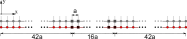
In this Appendix, we briefly describe the tight-binding (TB) simulation methods used in the main text to obtain Figures 2-8. We start by discretizing the Hamiltonian in Eqs. (1) and (II.1) on a square lattice in the usual manner: [111]
| (20) |
where is the lattice constant and are the and coordinates of the lattice points and are integers representing the () lattice point along the - (-) axis. The onsite () and hopping () terms do not have -dependence because we consider a system with translational invariance in the -direction, except in the cases where we consider the energy levels or the wavefunction amplitude of a 2D closed system [see Figs. 2(b) and 2(c), and Figs. 5(b) and 5(c)]. These terms are given by
| (21) |
Here, is the hopping parameter, is the effective mass and the definitions of , , , , , , and are given in the main text. is the minimum single particle energy, which is at least an order smaller than other relevant energies in the systems we consider. An illustration of the lattice discretization used for the numerical calculations is shown in Fig. 9.
In order to calculate the free energy in Eq. (10) as well as the topological gap, we need the energy spectrum of the system. The translational invariance in the -direction implies the momentum is a good quantum number. We utilize the Kwant package [92] to solve the relevant eigenvalue problem for a given :
| (22) |
where
| (23) |
Finally, to obtain the topological charge , we make use of the formula [78]
| (24) |
where is the Pfaffian and , are obtained using the Kwant package. [92, 112]
The system parameters used in the numerical simulations are summarized in Table 1.
| Name | HgTe | InSb |
|---|---|---|
| Effective mass ( ) | 0.038 | 0.013 |
| Landé factor () | -10 | -20 |
| Induced SC gap () | 0.25 meV | 0.21 meV |
| SOC strength () | 16 meV nm | 15 meV nm |
| Critical field at K | 1.45 T | 1.45 T |
| Temperature () | 0.7 K | 0.7 K |
| Chemical potential in S () | 1 meV | 1 meV |
| Chemical potential in N () | 1 meV | 1 meV |
| Junction width () | 96 nm | 96 nm |
| Left SC lead width () | 252 nm | 252 nm |
| Right SC lead width () | 252 nm | 252 nm |
| Junction length () | 4000 nm | 4000 nm |
| TB lattice constant () | 6 nm | 6nm |
| TB hopping parameter() | 27.9 meV | 81.5 meV |