A comparative study of the aerodynamic performance of box-wings and mono-wings at Low Reynolds number
Abstract
With technological advancements in autonomous aerial systems, Micro Aerial Vehicles (MAVs) have increased applications due to their small size, better maneuverability, and remote operability. Non-conventional designs, such as closed box-wing structures, have reduced induced drag, enabling a higher payload capacity, endurance, and aerodynamic efficiency. Current studies have widely studied the applicability of box-wing for large commercial aircraft, general aviation, and medium to large UAVs. Despite the increased work on non-conventional wing aircraft, little has been studied about the applicability of box-wing design over a monoplane in the MAV scale and the choice of parameters that enable the box wing to be best suited. This work presents numerical simulation results for box-wing configurations in contrast with the conventional monowing design, considering operations at lower Reynolds numbers and aspect ratios suitable for small UAV operations. We study the effects of lift, skin friction, and induced drag along with aerodynamic efficiency for six structures. It is intuitive to expect that the decreased induced drag would prove the box-wing design outperformed the conventional design. However, the additional parasitic drag generated makes the monowing model a slightly better choice. The simulations reveal that the box-wing lowers induced drag by 2 to 12% compared to a monowing aircraft but produces a lesser total lift to drag ratio by 10% at equal lift requirement. Our analysis also addresses the effect of varying aspect ratios and Reynolds numbers on the simulation results for the box-wing and monowing designs and discusses the suitability of choosing a particular structure based on mission requirements.
Nomenclature
| = | Aspect Ratio |
| = | Span |
| = | Root chord length (m) |
| = | Drag coefficient of wing |
| = | Zero-lift drag coefficient of wing |
| = | Skin friction drag coefficient of wing |
| = | Pressure drag coefficient of wing |
| = | Drag coefficient of airfoil |
| = | Lift coefficient of wing |
| = | Lift coefficient of airfoil |
| = | Pitching moment coefficient of wing |
| = | Leading Edge |
| = | Mean Aerodynamic Chord |
| = | Reynolds Number |
| = | Area |
| = | Angle of attack, deg () |
1 Introduction
Over the last decade, Micro Aerial Vehicles or MAVs have seen exponential growth and have received constant attention from researchers worldwide for applications in agriculture, medical supply delivery, search and rescue, military reconnaissance and surveillance operations, and infrastructure maintenance. Their wide application is primarily due to their small size, agility, and remote operability to keep human personnel from harm. Small aerial vehicle designs have a variety of profiles for lifting mechanisms such as fixed-wing, delta-wing, bi-plane, flapping-wing, including a rotary system-based multirotor [1]. Improvements in design included enhanced flow reattachment over the MAV wing surface for higher efficiency [2], tandem wing-based bi-plane for low-speed missions [3], coin-sized flapping-wing design MAV [4] and a mechanical realization for flapping wing [5]. Non-conventional fixed-wing designs, on the other hand, are mechanically simple and enable better drag reduction than conventional wing designs of the same span [6]. Non-conventional wings also increase the possibility of decreasing airframe weight, stalling speed, and increasing stalling angle and endurance, which are highly critical to MAVs [6, 7]. In our work, we investigate the closed wing design ‘box-wing’.
Box-wing design: L. Prandtl introduced Box-wing design in 1942 as the "Best Wing System", which satisfies the condition of same lifting distribution on both the upper and lower wings and a center symmetric lift distribution from the middle of vertical joining surface like a butterfly-shaped lift distribution; the velocity induced by free vortices is constant along with the horizontal wings and symmetrically zero on the vertical joining wings [6]. Previous studies have shown the box-wing achieves the lowest drag for a fixed height to span (h/b) ratio [6] and determined the relationship between the inverse span efficiency factor for box-wing and h/b [8, 9] showing a higher efficiency, better lift-to-drag ratio and lower induced drag [10]. Several studies have considered it a potential design for commercial airliners [11] and transonic aircraft [12, 13].
Attempts have been made to design, optimize, and prototype a Canard Prandtl box-wing aircraft for a Low-Altitude Long-Endurance UAV system to extend imaging campaigns and beyond horizon communication to support remote exploration, post-disaster assessment, and assistance [14]. In the cruise phase, the box-wing was 42.6% efficient than a similar TW configuration. The efficiency gain was attributed to the box wing’s unique capability to shift its optimal lift distribution to meet the specified constraints. Further studies have shown that a box-wing sweep, stagger, and taper ratio do not affect the induced drag if suitable span loading is maintained; instead, it increases with the increase in the dihedral, and the height to span ratio has the highest dependence on the efficiency [15]. For h/b <0.2, the gap to span ratio parameter and aspect ratio are essential in the induced drag but higher values of h/b offer lower induced drag as the wing taper increases when compared to a conventional mid-range size aircraft [16]. A few downsides of box-wing aircraft include the early onset of flutter [13] and increase in parasitic drag [17], but while deploying box-wings for MAVs, these downsides are either diminished or disappear altogether. For a miniature UAV carrying small computers, sensors, and optical sensing equipment, a non-planar box-wing model has potential to achieve the desired goals of a Small Reconnaissance Surveillance [18]. For such small UAVs, the Reynolds number of operations will be low due to slower operational velocity. At such low Reynolds numbers, the zero-lift drag is highly dependent on itself, leading to different results as compared to other regimes.
Selection of design: Though box-wings have seen considerable research for passenger aircraft, their study as a lifting mechanism for small aerial vehicles has been relatively unexplored. It has potential in both aerodynamic and structural domains. Our work in this paper addresses the use of box-wing for MAVs. Non-conventional wing designs have different definitions of geometric parameters. The selection of a suitable aircraft design depends on factors such as the Reynolds number , aspect ratio , wetted area , chord of the aircraft. The choice of the most efficient design involves consideration of these parameters and requires thorough investigation before selection. For a MAV, the most salient aspect is its low endurance, which often does not exceed a few minutes. Thus, it is crucial to investigate maximizing the endurance and range by reducing the aircraft’s drag.
Contributions: The objective of this study is to present a way to determine how efficient a box-wing design is when compared to monowing to reduce induced drag and increase aerodynamic efficiency. We study different box-wing and monowing models and compare their performances with respect to the induced drag, skin friction drag and show the best regime suitable for the aircraft configurations. As box-wing designs have shown to produce a lower induced drag, it is natural to expect the boxwing to outperform the monowing configuration in terms of overall efficiency. However, our results show the box-wing generates additional parasitic drag that increases the total drag of the model and decreases the total L/D. This makes the monowing slightly better when the total lift requirement in the mission is lower. As the L/D is a critical factor in determining the aircraft’s range and endurance, we show a direction to determine the configuration to be chosen based on the mission requirements.
Outline: The paper is arranged in the following sections. Section 2 provides the details of the wing designs, meshing, boundary conditions, CFD analysis settings, and grid convergence tests. We present the validation studies of our computational analysis in Sec 3 against previous experimental and numerical simulation data [19, 20]. The important results and discussions are presented in Sec 4. We conclude and outline future works and applications in Sec 5.
2 Computational Analysis/ Methods
2.1 Geometry Model and Case Description
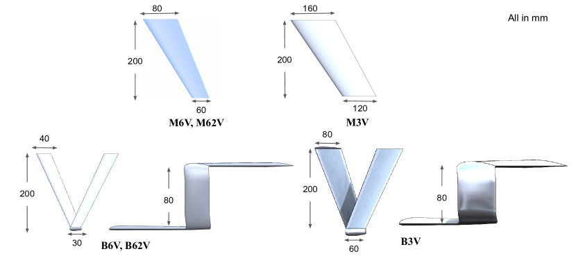
A conventional swept back mono-wing model is designed and selected as reference for this comparative study from our prior work on experimental comparison of box-wing and mono-wing [21]. The wing is created with the Clark Y airfoil, and has a root chord length() of 200mm, semi-span() of 200mm, taper ratio of and sweep angle of . We use the nomenclature for this model as M6V, indicating this to be a mono-wing model with aspect ratio = 6 and velocity V = 22.14 m/s. A box-wing, B6V, corresponding to same mission profile (projected area, wing span, half root chord, lift and cruise speed) is created and has area ratio = 0.5, stagger = 0.46 and gap/height h/b = 0.2. A higher value of h/b would offer a lower induced drag, however the increased winglet height would require additional structural reinforcement to prevent flutter [16]. M62V and B62V are cases with twice the cruise speed created to study the effect of Reynolds number. Additionally two models M3V and B3V, are created with half to study the effect of aspect ratio. The specifications of each experiment’s model geometry are shown in Fig. 1 and Table 2 as Cases M6V-B3V.
| Model | Type | MAC | Span | Total Area | Velocity | ||
|---|---|---|---|---|---|---|---|
| (c = 70 mm) | (b = 400 mm) | (S = 0.028 ) | () | () | (m/s) | ||
| M6V | Monowing | c | b | S | 6 | 1.50 | 22.14 |
| M62V | Monowing | c | b | S | 6 | 3.00 | 44.28 |
| M3V | Monowing | 2c | b | 2S | 3 | 3.00 | 22.14 |
| B6V | Box-wing | 0.5c | b | S | 6 | 0.75 | 22.14 |
| B62V | Box-wing | 0.5c | b | S | 6 | 1.50 | 44.28 |
| B3V | Box-wing | c | b | 2S | 3 | 1.50 | 22.14 |
2.2 Domain and boundary conditions
The simulations were performed on the half-wing taking into account symmetry of the flow. A semi-spherical flow domain of radius 10 root chord length () was used. The spherical surface was set as far-field, the plane surface of the hemisphere as symmetry and wing surface as no-slip wall boundary conditions.
2.3 Flow Solver
The finite volume-based CFD simulations are performed using SU2 v7.0.6 to solve incompressible Reynolds-averaged Navier–Stokes (RANS) equation. The Menter’s Shear Stress Transport, a two-equation turbulence model, is used with the RANS equation to accurately analyze flows near walls and freestream. Upwind Flux Difference Splitting(FDS) scheme is the convective numerical method used in SU2. The implicit Euler method is used for time discretization. The Flexible Generalized Minimal Residual method (FGMRES) is the linear solver used. The convergence criteria of the linear solver are set to drag value, with the minimum residual value set to .
2.4 Mesh
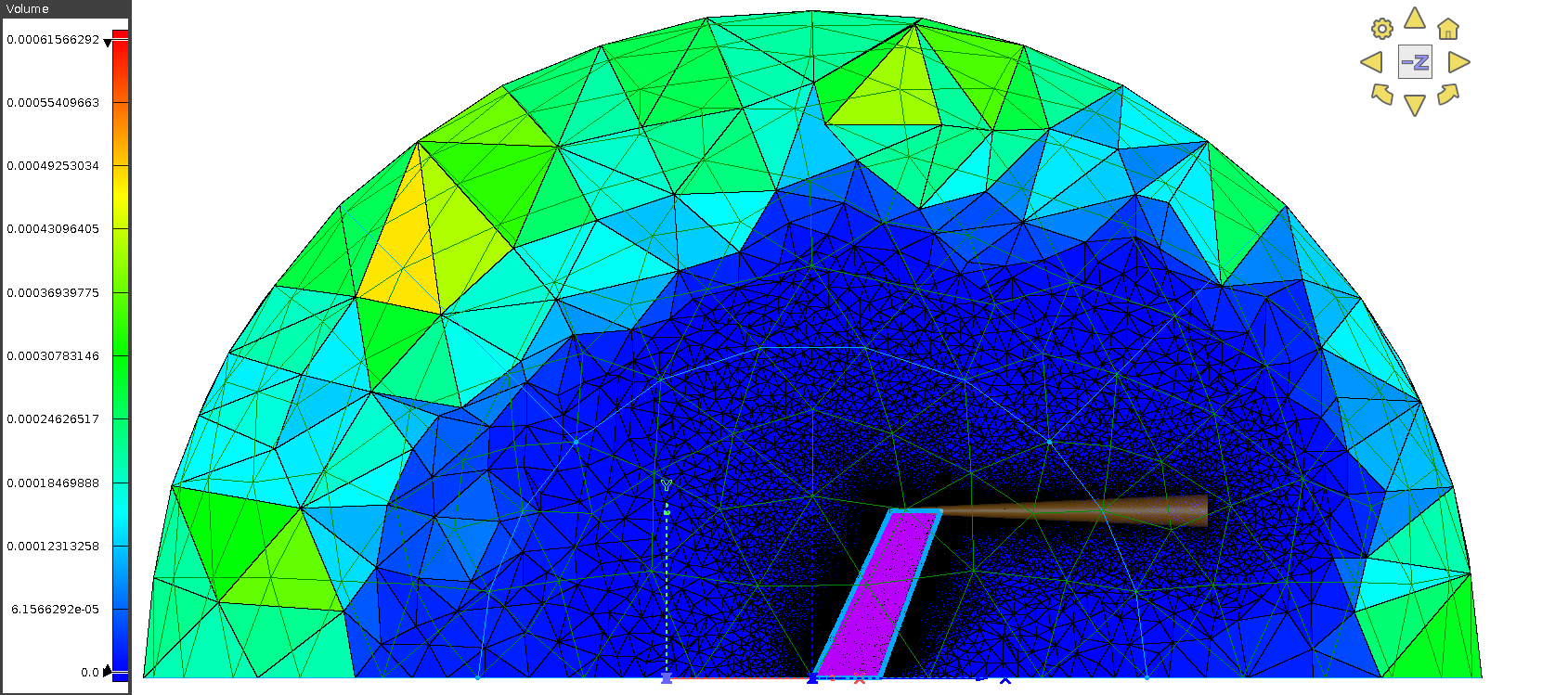
An unstructured isotropic triangular mesh Type 2, (see Table 4), was generated on all the surfaces with average grid point spacing on the wing surface and flow domain boundary surface as 2 mm and 40 mm, respectively, for all models. Twenty layers of anisotropic mesh refinement with growth rate 1.1 were done on the leading and trailing edges of the wings to capture the changes in flow. 30 anisotropic tetrahedral layers with a growth rate of 1.1 were generated in the volume mesh adjacent to the wings. The gridpoint spacing for the layer adjacent to the wing was taken to be 0.015 mm to get 1 at the wing surface. The total number of cells and grid points are also given in the Table 3. A conical source was placed at the wingtip with its axis extended from 0.0 to 6.0 (location in terms of x/c) and the grid spacing of 3.5e-5 m at the beginning to 3.5e-3 m at the end. The influence of the source can be visualized in Fig. 2.
| M6V | M62V | M3V | B6V | B62V | B3V | |
|---|---|---|---|---|---|---|
| Total number of Cells (millions) | 9.7 | 9.7 | 14.7 | 17.6 | 17.6 | 26.9 |
| Total number of Points (millions) | 2.6 | 2.6 | 3.9 | 3.9 | 3.9 | 6.5 |
2.5 Grid convergence
| Grid Type | No. of Elements | L/D | ||||
|---|---|---|---|---|---|---|
| Type 1 | 8.14 million | 0.5491 | 0.0386 | 0.0262 | 0.0124 | 14.21 |
| Type 2 | 9.7 million | 0.5445 | 0.0363 | 0.0239 | 0.0125 | 12.19 |
| Type 3 | 19.84 million | 0.5402 | 0.0360 | 0.0235 | 0.0125 | 12.37 |
A grid sensitivity test was performed for Model M6V using two additional grid types whose properties are shown in Table 4 at . Grid Type 3 was created with fine grid spacing reaching the upper limit of tolerance of Type 2 was generated by increasing the number of points and decreasing spacing to get a refined grid. Grid Type 1 was created by reducing the number of points by half and increasing the spacing by two times to get a coarse grid. We use the parameters of , , and L/D to finalize the grid size. From Type 1 grid to Type 2 grid, we observe a small difference in values of (0.84%) and (5.96%). Similarly, comparing values from Type 2 grid to Type 3 grid, we note the further reduction in the differences (0.8%) and (0.94%). The Type 3 grid requires required more computational time per iteration, and consequently, the overall time required is higher. We thus finalize the Type 2 grid specification to get accurate data with a shorter computation time.
3 Validation Studies
We conduct a validation study for the comprehensiveness of our computational analysis using three-dimensional simulation of a rectangular wing [19, 20]. A numerical study of LAR wings at low Reynolds number by Cosyn and Vierendeels [19] and the experimental analysis of the same has been done by Torres and Mueller [20]. Simulation for the wing of AR = 1 at is done to verify the numerical model used in our study. The lift coefficient and drag coefficient of our grid at low angles of attack are found to be approximately the same as the results in Cosyn and Vierendeels [19] and Torres and Mueller [20]. At higher angles of attack, there is a slight underprediction of drag coefficient as compared to the experimental result [20] but slightly better than that predicted by [19]. The lift coefficient is slightly higher than that shown in the studies.
4 Results and Discussion
This section first presents the parametric study: effect of Reynolds number and aspect ratio on mono-wing and box wing separately. The box-wing models are then compared against mono-wing for aerodynamic performance and stability.
4.1 Effect of Reynolds number
4.1.1 Monowing
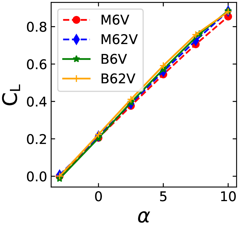
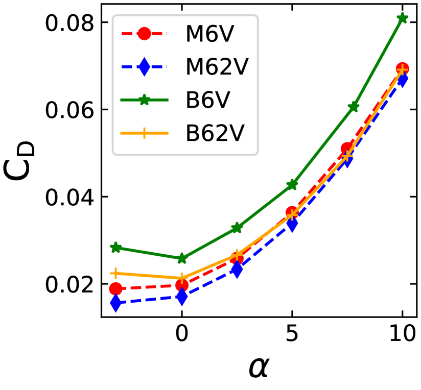
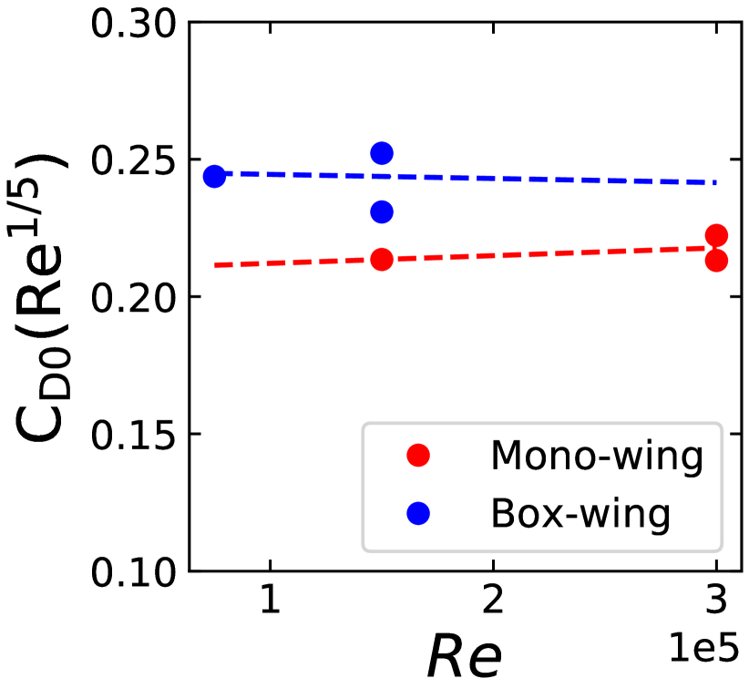
We evaluate the effects of the Reynolds number on the aerodynamic force coefficients: lift coefficient and drag coefficient for mono-wing cases M6V and M62V. Both the cases have the same wing models but different refer to Table 2. Fig. 4(a), reveals that as we increase the Reynolds number from 1.5x to 3.0x the increases however the increase is not significant. On the other hand, decreases remarkably as increases as shown in figure 4(b). The decrease in drag is mainly due to reduced drag at zero AOA ( or ). This can be attributed to the coefficient of skin friction drag being inversely proportional to the fifth root of Reynolds number as seen in figure 4(c) comparing . From Fig. 4(d), we observe no strong dependence of Reynolds number on induced drag.
4.1.2 Box-wing
For the box-wing, we choose models B6V and B62V and observe the is approximately constant. Thus, we note no drastic effect of these Reynolds number ranges on the lift coefficient of both models. For the box-wing cases B6V and B62V, we see decreases as increases. We also observe that B6V has a higher compared to B62V. This can be attributed to the decrease in the .
4.2 Effect of Aspect Ratio
4.2.1 Monowing
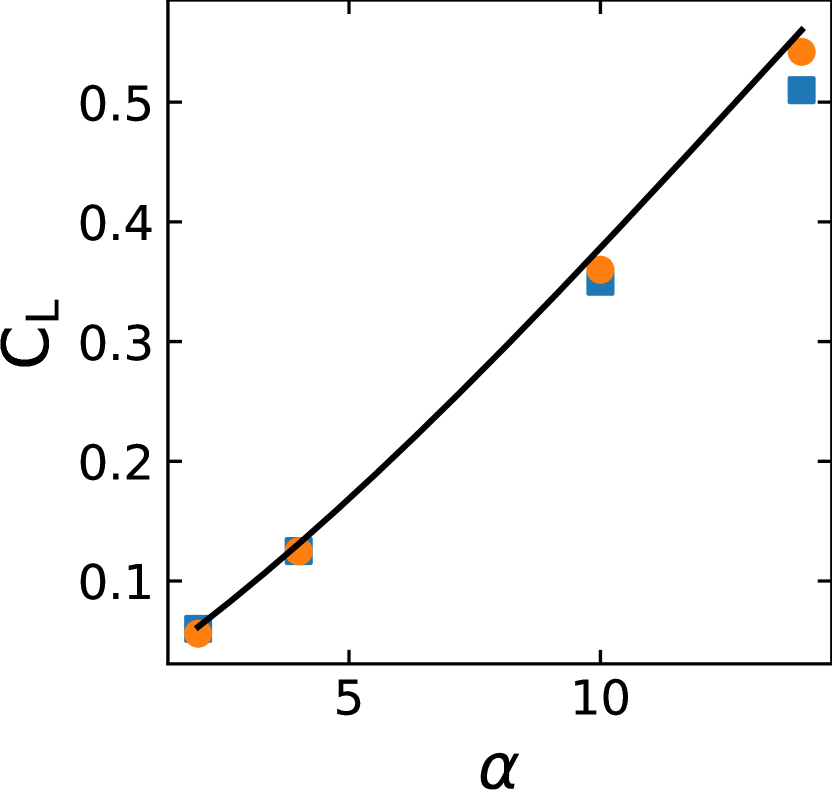
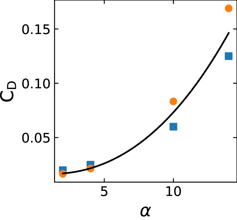
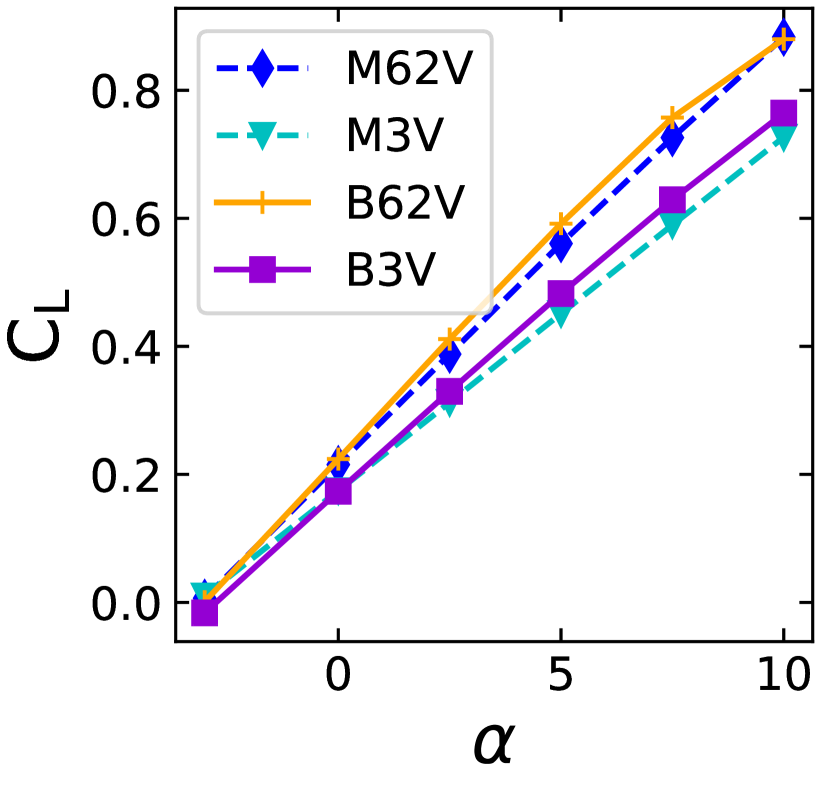
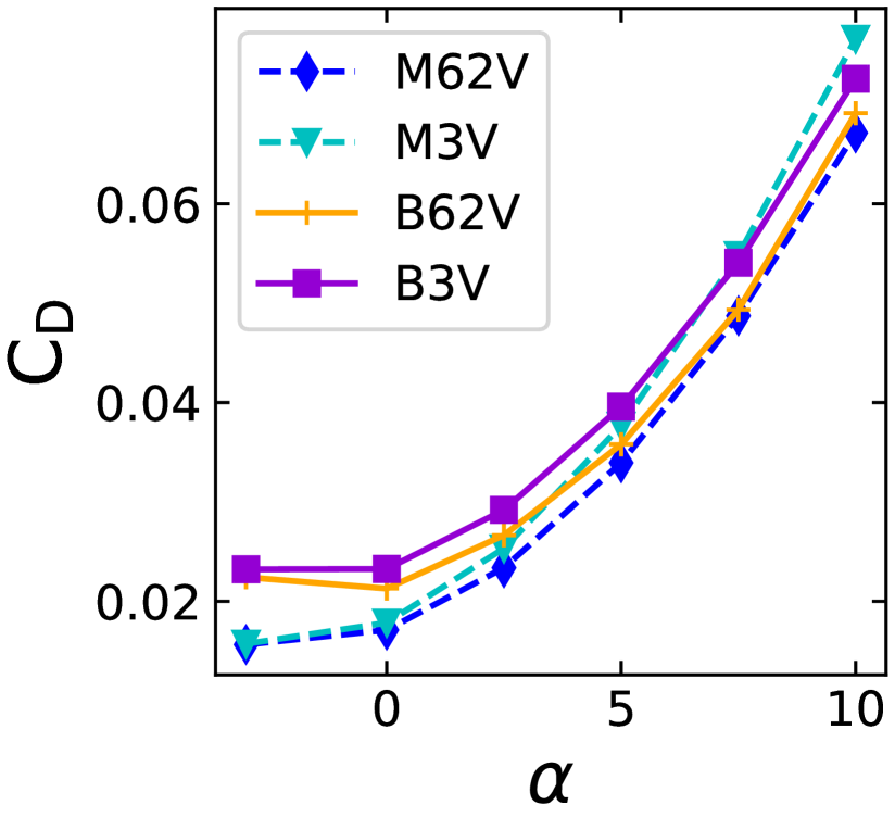
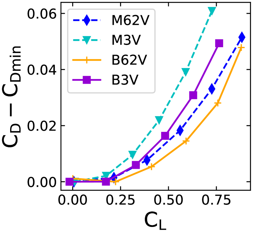
Comparing the effect of for the monowing cases M62V and M3V, which have the same = 3.0e05, from Fig. 5(a), we observe that the lift coefficient slope, , and subsequently increases with an increase in the . For the monowing, the drag coefficient decreases while the minimum drag coefficient is not affected by the change in . Hence we compare only the induced drag, i.e., the component of drag dependent on , using - for various . We notice that as increases, induced drag - decreases.
4.2.2 Box-wing
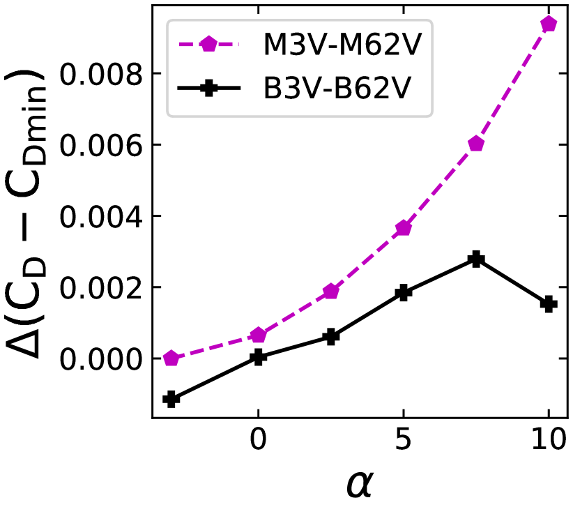
For box-wing models (B62V and B3V), we notice that the lift coefficient slope, , and subsequently increases with an increase in the . We notice that as increases, - decreases. The difference, -, is smaller for box-wing as compared to the monowing cases. At , we notice that the monowing - is four times - of the box-wing. We can conclude that an aspect ratio change significantly impacts the coefficient of drag for a monowing model, whereas the box-wing model only has a minor variation.
4.3 Comparison of Box-wing and Monowing
4.3.1 Aerodynamic Characteristics
We compare monowing and box-wing models at same and , making them suitable candidates theoretically.
We observe from Table 5 that the change in lift produced at is much more significant than the change in drag. This leads to the B62V producing a higher Lift to Drag Ratio as compared to the M6V. It can be attributed to the higher velocity of operation for B62V, which would generate a different mission profile than required for the same monowing model. However, it is not always possible to choose the double the UAV velocity for operating at the same , keeping all other parameters constant.
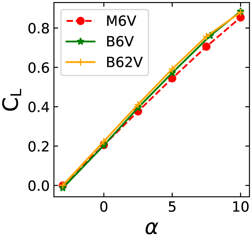
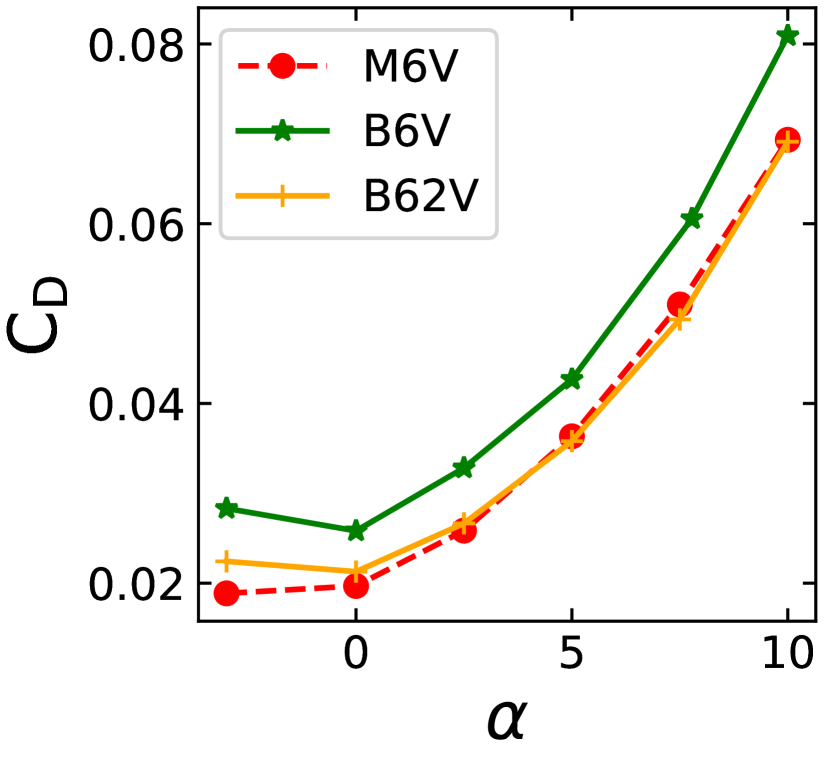
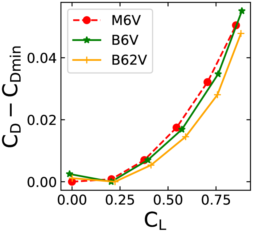
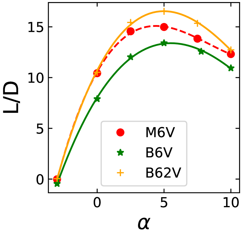
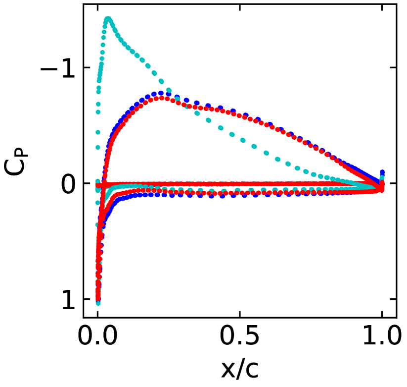
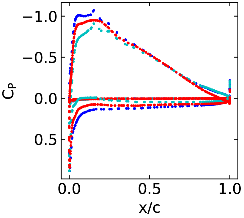
From a designer’s perspective, it is more suitable for comparing the monowing and box-wing cases at same mission profile ( similar lifting area, same operating speed, same ). Comparing the case M6V and B6V, Fig.6(a) shows that Box-wing B6V has slightly higher lift coefficient slope, and consequently higher total lift than Mono-wing case M6V. In Fig.6(b), we notice that of B6V is greater than of M6V. These observations can be attributed to the lower of B6V, contributing to an increased drag for the box-wing as explored in section 4.1, and additional parasitic drag for the winglet surface absent in the monowing. Fig.6(c), compares induced drag for M6V and B6V at same , and reveals that box-wing has slightly lower drag compared to mono-wing M6V. The effect of is also dominant, thus, their combined effect causes significant increase in total drag with small increase in lift, resulting in lower efficiency for box-wing as seen in Fig. 6(d)
| Case | M6V | M62V | M3V | B6V | B62V | B3V |
|---|---|---|---|---|---|---|
| 0.5445 | 0.5606 | 0.4512 | 0.5722 | 0.5916 | 0.4825 | |
| 0.0363 | 0.0339 | 0.0377 | 0.0427 | 0.0358 | 0.0396 | |
| 14.9846 | 16.5178 | 13.9750 | 13.4033 | 16.5252 | 12.1891 |
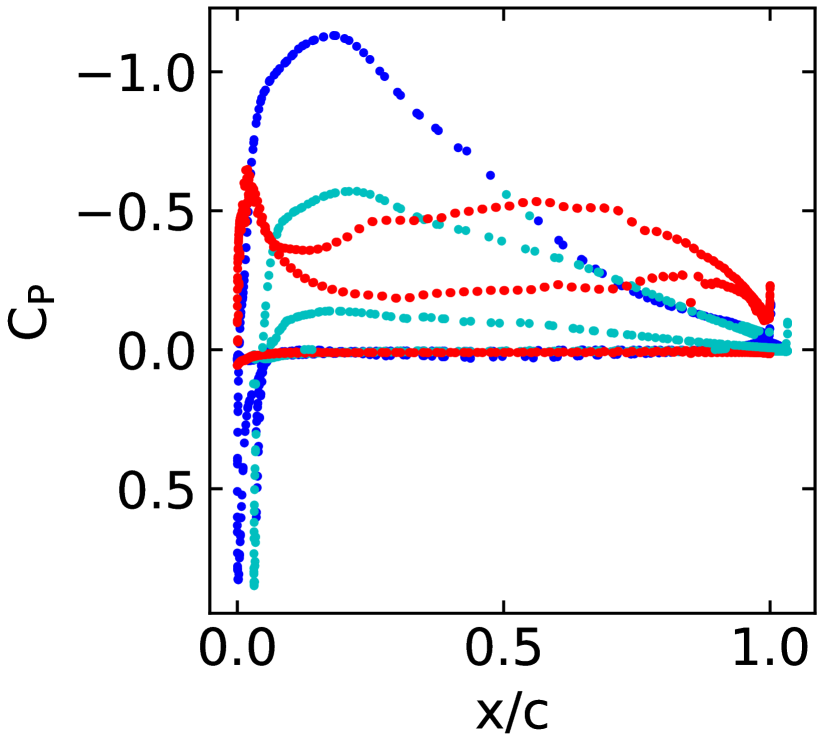
4.3.2 Flow Visualization and Pressure Distribution
Doing a qualitative comparison of the vortex visualizations for a box-wing and monowing shown in Fig. 7(a), we observe that the strong wing tip vortex of a monowing breaks down into weaker two vortices in a box-wing. This can be an advantage while designing an aircraft, as weaker vortices get diffused faster, making it safer for other aircraft to fly behind it. The flow on forward swept wings moves inwards towards the root.
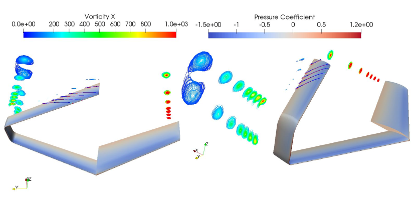
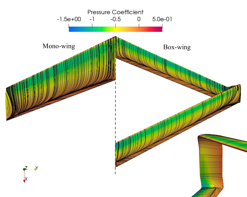
The pressure distribution can explain increased lift in Box wing compared to Mono-wing.
4.3.3 Induced Drag
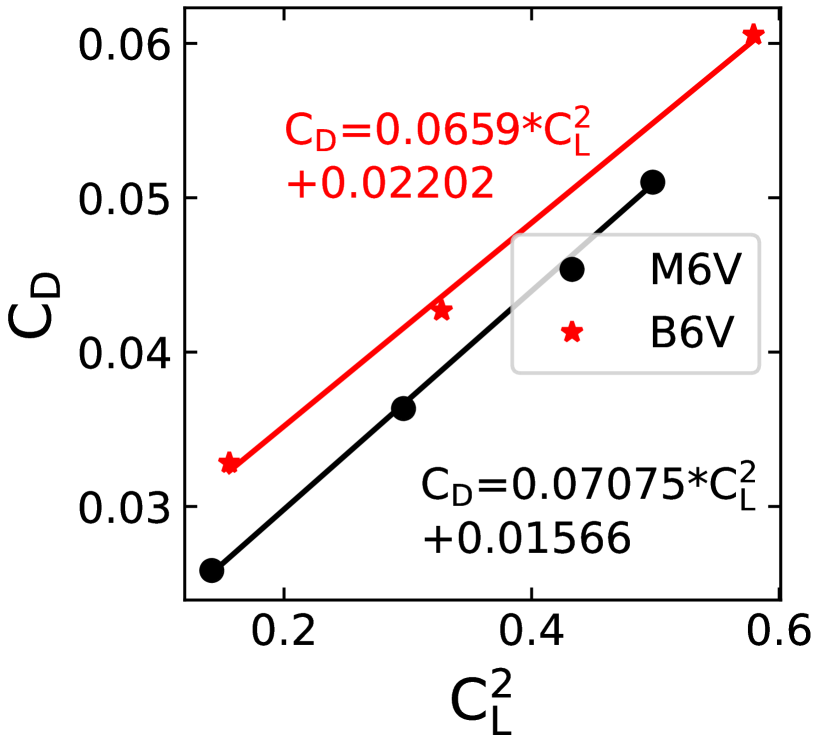
Next, we do a quantitative analysis to understand the aerodynamic effect of a box-wing in detail. The drag polar for a finite wing is represented by
| (1) |
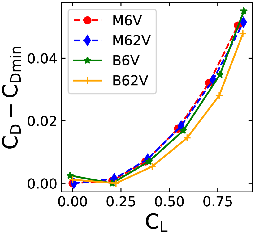
The pressure component of the profile drag coefficient and the induced drag coefficient vary with the square of the wing’s lift coefficient. The second term includes the contribution of induced drag and sectional-pressure drag, and the induced drag factor, , can be determined from the slope of vs. (Fig. 8 from [22]). In plot Fig. 9(a), we have plotted vs. , for models M6V and B6V. Calculating the slope by plotting a line using a line fitting method, we find that the slope for M6V is higher than B6V.
We compare the high fidelity numerical simulation (SU2) results to the vortex lattice method of determining induced drag coefficient () using a parametric geometry software like OpenVSP and find the agreement of the methods with a difference of less than 7%, proving the correctness of our high fidelity numerical simulation (SU2) results with Traub’s approach, and more precise as compared to OpenVSP in Table 6.
| Method | Model | |||||
|---|---|---|---|---|---|---|
| Numerical Simulation / RANS ([22]) | ||||||
| M6V | 0.0708 | 0.5445 | 0.0363 | 0.021 | 0.0157 | |
| B6V | 0.0659 | 0.5722 | 0.0427 | 0.0206 | 0.0220 | |
| M3V | 0.1168 | 0.4512 | 0.0377 | 0.0238 | 0.0141 | |
| B3V | 0.0847 | 0.4825 | 0.0396 | 0.0197 | 0.0203 | |
| Vortex Lattice (OpenVSP) | ||||||
| M6V | 0.0589 | 0.5803 | 0.0368 | 0.0198 | 0.017 | |
| B6V | 0.0425 | 0.6392 | 0.0402 | 0.0174 | 0.0228 | |
| M3V | 0.1149 | 0.4461 | 0.0369 | 0.0229 | 0.0141 | |
| B3V | 0.0846 | 0.5015 | 0.0403 | 0.0213 | 0.019 |
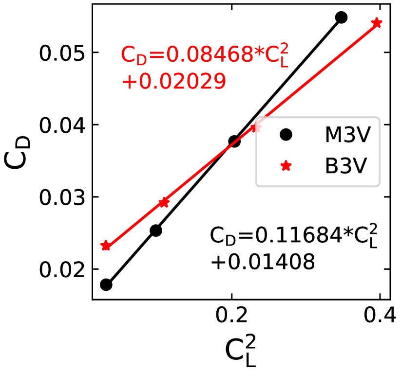
Table 6 confirms that induced drag coefficient is lower for a box-wing as compared to a mono-wing at both the aspect ratio . However, the change in induced drag coefficient, depends on the . From Fig. 9(a) and Fig. 9(b), we notice that a change in the slope is greater when the aspect ratio lowers. Hence, boxwing is more effective at reducing induced drag at a lower aspect ratio.
When the wing has a high aspect ratio, the effect of Reynolds number on drag is not as significant as compared to low aspect ratio regimes. Due to the small slope of vs. plot, at larger Reynolds number, previous literature considering box-wing transonic or commercial airliners have not studied the impact of Reynolds number on the operations during comparison with a monowing design. When the Reynolds number is lower, the effect of drag and is higher, and this is an essential factor when deciding the choice of aircraft design in the small UAV regime.
4.3.4 Comparison under equal lift generation constraint
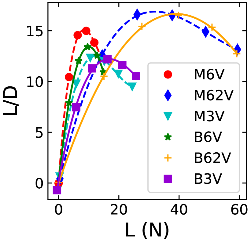
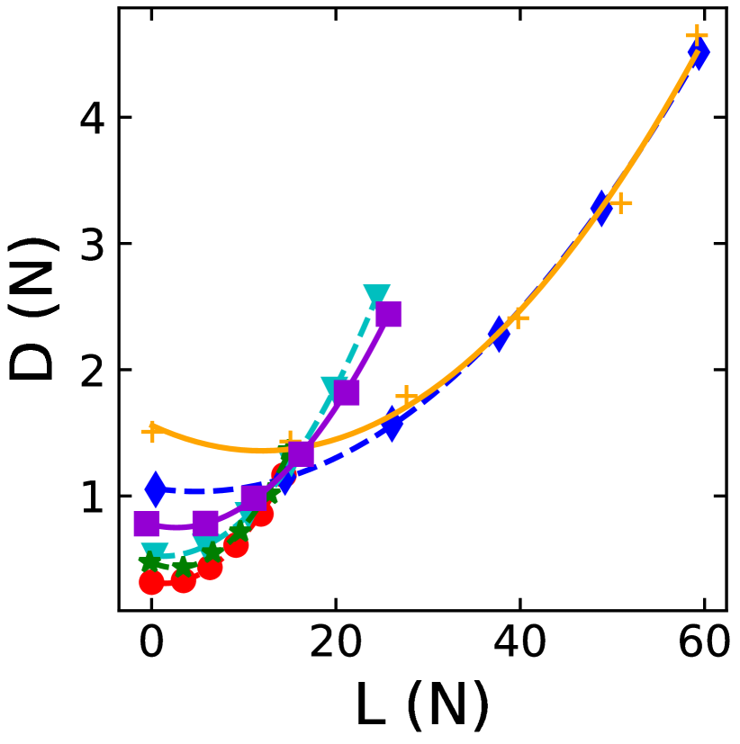
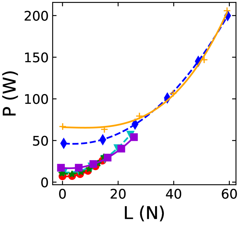
In Fig. 10(a), we show the variations of L/D and D with respect to total lift. The figure reveals that the monowing M6V has 10% higher L/Dmax than the box-wing B6V. Further, at the same , the difference in L/Dmax decreases to 2% as the lift design requirement increases, suggesting that the box-wing might perform better at higher lift required conditions. This is attributed to a higher increase in lift rather than a decrease in drag, as indicated in previous studies that use low fidelity simulations. In Fig. 10(c) we show the cruise power required vs the total lift of aircraft models. For models M62V and B62V, we see the total drag is lower for B62V at larger lift requirements between 40 to 60 N. The power requirements is also lower for B62V. This implies that at higher lift the box wing consumes slightly less power.
4.3.5 Longitudinal Static Stability
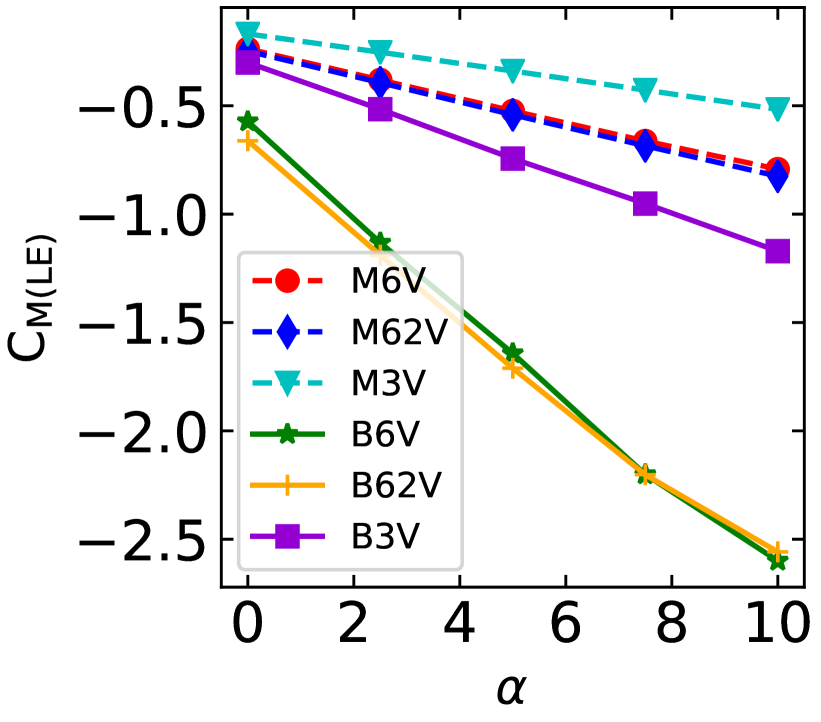
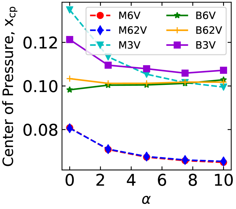
The coefficient of moment about the leading edge for all models at different is plotted in Fig. 11(a). The results show the box-wing models to be most stable compared to the monowing models. We also plot the center of pressure for different models over the range of angles in Fig. 11(b). We see the center of pressure moves forward for all models . We also observe the box-wing models have a farther center of pressure compared to the monowing models M6V and M62V. This provides the box-wing a longer moment arm and enhances the nose-down moment for additional stability.
5 Conclusion and Future Works
We present the aerodynamic analysis of a conventional monowing design to a box-wing design at the small UAV scale. The comparison of the monowing and a box-wing design is not trivial as a non-conventional design such as a closed wing box-wing aircraft has different definitions of parameters. The aerodynamic characteristics of a box-wing are compared to that of a by varying geometric parameters of the chord, area, and aspect ratios, providing different Reynolds numbers of operation. We show that the box-wing produces a lower induced drag when compared to the monowing of the same aspect ratio. This is primarily due to the breaking of the large wing tip vortex from the monowing into two weak vortices in the box-wing. The box-wing also exhibits a higher total drag due to a higher parasitic drag () as compared to the monowing at equal . This results in a lower total L/D than the conventional design at a lower total lift. When the lift requirement increases, we see an increase in the lift to drag coefficient suggesting a box-wing configuration is better suited for high-lift applications.
There is a large scope for design optimization and further efficiency increment of the box-wing design for small UAV and MAV applications. Using multi-objective optimization, the wing geometry can be modified to enable better performance for different flight conditions. Modification of the geometry can lead to lower parasitic drag and can lead to a significant improvement in aerodynamic efficiency. High maneuverability requirements of a MAV necessitate non-traditional methods of control suitable for models of this scale. The box-wing configuration has the potential to be a better choice than a monowing configuration for areas of surveillance, micro-payload transport such as vaccine and medicine delivery. Additionally, when deploying the model in the real world, unpredictable gusts may cause higher stresses on the aircraft. There is an enormous scope in optimizing the wing structurally, taking into consideration the aerodynamics of a box-wing.
Acknowledgments
The authors would like to acknowledge the computational facilities provided by the Department of Aerospace Engineering, and we acknowledge the National Supercomputing Mission (NSM) for providing computing resources of ‘PARAM Shakti’ at IIT Kharagpur, which is implemented by C-DAC and supported by the Ministry of Electronics and Information Technology (MeitY) and Department of Science and Technology (DST), Government of India.
References
- Moschetta [2014] Moschetta, J.-M., “The aerodynamics of micro air vehicles: technical challenges and scientific issues,” Int. J. Engineering Systems Modelling and Simulation, Vol. 6, No. 3/4, 2014, p. 134–148.
- Di Luca et al. [2020] Di Luca, M., Mintchev, S., Su, Y., Shaw, E., and Breuer, K., “A bioinspired Separated Flow wing provides turbulence resilience and aerodynamic efficiency for miniature drones,” Sci Robot, Vol. 5, No. 38, 2020. 10.1126/scirobotics.aay8533.
- Thipyopas and Jean-Marc [2009] Thipyopas, C., and Jean-Marc, M., “A fixed-wing biplane MAV for low speed missions,” International Journal of Micro Air Vehicles, Vol. 1, No. 1, 2009, pp. 13–33.
- Wood [2007] Wood, R., “Design, fabrication, and analysis of a 3DOF, 3cm flapping-wing MAV,” Proc. of The International Conference on Intelligent Robots and Systems (IROS), 2007, pp. 1576 – 1581. 10.1109/IROS.2007.4399495.
- Conn et al. [2006] Conn, A., Burgess, S., Hyde, R., and Chung, S., “From Natural Flyers to the Mechanical Realization of a Flapping Wing Micro Air Vehicle,” 2006 IEEE International Conference on Robotics and Biomimetics, 2006, pp. 439–444. 10.1109/ROBIO.2006.340232.
- Kroo [2005] Kroo, I., “Non-planar Winng Concepts For Increased Aircraft Efficiency,” VKI Lectire Series on Innivative Configurations and Advanced Concepts for Future Civil Aircraft, 2005.
- Khalid and Kumar [2014] Khalid, A., and Kumar, P., “Aerodynamic optimization of box wing–a case study,” International Journal of Aviation, Aeronautics, and Aerospace, Vol. 1, No. 4, 2014, p. 6.
- Frediani and Montanari [2009] Frediani, A., and Montanari, G., Best wing system: an exact solution of the Prandtl’s problem, Springer New York, New York, NY, 2009, pp. 183–211.
- Gagnon and Zingg [2016a] Gagnon, H., and Zingg, D. W., “Euler-Equation-Based Drag Minimization of Unconventional Aircraft Configurations,” Journal of Aircraft, Vol. 53, No. 5, 2016a, pp. 1361–1371. 10.2514/1.C033591, URL https://doi.org/10.2514/1.C033591.
- Kaparos et al. [2018] Kaparos, P., Papadopoulos, C., and Yakinthos, K., “Conceptual design methodology of a box wing aircraft: A novel commercial airliner,” Proceedings of the Institution of Mechanical Engineers, Part G: Journal of Aerospace Engineering, Vol. 232, No. 14, 2018, pp. 2651–2662. 10.1177/0954410018795815, URL https://doi.org/10.1177/0954410018795815.
- Jemitola and Fielding [2012] Jemitola, P., and Fielding, J., “Box wing aircraft conceptual design,” 28th Congress of the International Council of the Aeronautical Sciences 2012, ICAS 2012, Vol. 1, 2012, pp. 570–579.
- Miranda [1973] Miranda, L. R., “Boxplane Wing and Aircraft,” 1973.
- Gagnon and Zingg [2016b] Gagnon, H., and Zingg, D. W., “Aerodynamic Optimization Trade Study of a Box-Wing Aircraft Configuration,” Journal of Aircraft, Vol. 53, No. 4, 2016b, pp. 971–981. 10.2514/1.C033592, URL https://doi.org/10.2514/1.C033592.
- de vivo et al. [2019] de vivo, L., Tran, D., Kuester, F., and Dronelab, “Towards Design of a 3D Printable Prandtl Box-Wing Unmanned Aerial Vehicle,” 2019. 10.1109/AERO.2019.8741628.
- Khan [2010] Khan, F., “Preliminary aerodynamic investigation of box-wing configurations using low fidelity codes,” 2010.
- Ribeiro et al. [2017] Ribeiro, F., De paula, A., Scholz, D., and Silva, R., “Wing geometric parameter studies of a box wing aircraft configuration for subsonic flight,” 2017. 10.13009/EUCASS2017-447.
- Andrews and Perez [2018] Andrews, S. A., and Perez, R. E., “Comparison of box-wing and conventional aircraft mission performance using multidisciplinary analysis and optimization,” Aerospace Science and Technology, Vol. 79, 2018, pp. 336–351. https://doi.org/10.1016/j.ast.2018.05.060, URL https://www.sciencedirect.com/science/article/pii/S1270963818304516.
- Landolfo and Altman [2008] Landolfo, G., and Altman, A., Aerodynamic and Structural Design of a Small Nonplanar Wing UAV, 47th AIAA Aerospace Sciences Meeting, 2008, p. 1068. 10.2514/6.2009-1068, URL https://arc.aiaa.org/doi/abs/10.2514/6.2009-1068.
- Cosyn and Vierendeels [2006] Cosyn, P., and Vierendeels, J., “Numerical Investigation of Low-Aspect-Ratio Wings at Low Reynolds Numbers,” Journal of Aircraft, Vol. 43, No. 3, 2006, pp. 713–722. 10.2514/1.16991, URL https://doi.org/10.2514/1.16991.
- Torres and Mueller [2004] Torres, G. E., and Mueller, T. J., “Low Aspect Ratio Aerodynamics at Low Reynolds Numbers,” AIAA Journal, Vol. 42, No. 5, 2004, pp. 865–873. 10.2514/1.439, URL https://doi.org/10.2514/1.439.
- Singh et al. [2020] Singh, M., Aloor, J. J., Singh, A., and Saha, S., “Box Wing: Aerodynamic experimental study for applications in MAVs,” National Conference on Wind Tunnel Testing (NCWT-06), National Wind Tunnel Facility, India, 2020. 10.31219/osf.io/3r79q, URL https://doi.org/10.31219/osf.io/3r79q.
- Traub [2009] Traub, L. W., “Analytic drag prediction for cambered wings with partial leading edge suction,” Journal of Aircraft, Vol. 46, No. 1, 2009, pp. 312–319.