∎
22email: sg@igcar.gov.in 33institutetext: A. Nagesha 44institutetext: Scientific Officer-G & Head, Fatigue Studies Section, Materials Development and Technology Division, Metallurgy and Materials Group, Indira Gandhi Centre for Atomic Research, HBNI, Kalpakkam, Tamilnadu-603102, India
Atomistic simulations of twin boundary effect on the crack growth behaviour in BCC Fe
Abstract
In this paper, the effect of twin boundaries on the crack growth behaviour of single crystal BCC Fe has been investigated using
molecular dynamics simulations. The growth of an atomically sharp crack with an orientation of (111)110 (crack plane/crack
front) has been studied under mode-I loading at constant strain rate. In order to study the influence of twin boundaries on the
crack growth behaviour, single and multiple twin boundaries were introduced perpendicular to crack growth direction. The results
indicate that the (111)110 crack in single crystal BCC Fe grows in brittle manner. However, following the introduction of
twin boundaries, a noticeable plastic deformation has been observed at the crack tip. Further, increasing the number of twin
boundaries increased the amount of plastic deformation leading to better crack resistance and high failure strains. Finally, an
interesting relationship has been observed between the crack growth rate and flow stress.
Keywords:
Molecular dynamics simulations BCC Fe Twin boundaries Crack propagation Crack resistance1 Introduction
Twin boundaries (TBs) were special class of boundaries with lowest interface energy and high degree of symmetry. TBs contain arrangements of atoms that are mirror reflections of those on the other side, separated by twin plane. The low energy of TBs results in a number of superior properties relative to conventional grain boundaries (GBs). For example, it has been found that the TBs enhance the strength without loss of ductility lu2009revealing ; li2010dislocation , improve fracture toughness and crack resistance qin2009enhanced ; singh2011fracture ; liu2014atomistic , improve corrosion resistance and strain rate sensitivity deng2010effects . Moreover, the TBs posses high thermal and mechanical stability anderoglu2008thermal ; wang2013structure . Due to these unique properties, the materials containing high density of TBs attracted a lot of interest in materials community.
In the past, many studies have been carried out to understand the strengthening and softening mechanisms due to the presence of TBs in FCC lu2009revealing ; li2010dislocation and BCC sainath2016deformation ; xu2017size ; xu2018deformation materials. Further, the role of TBs on the crack propagation behaviour in FCC materials is also well understood liu2014atomistic ; zhu2011modeling . It has been shown that the TBs in FCC materials enhance the crack growth resistance due to different dislocation-twin and crack-twin interactions. For example, molecular dynamics (MD) simulations in twinned Cu have shown that the dislocations nucleated from the crack tip accumulate at the TBs and produce strain hardening which results in high plastic deformation and crack blunting zhu2011modeling . TBs also deflect the crack propagation path in Ag due to change in slip plane orientation across the boundary liu2014atomistic . The periodic deflection of crack path by TBs result in fracture with zigzag cracks in nanotwinned Cu zeng2015fracture . Apart from crack blunting and deflection, the crack arrest and crack closure have also been observed due to twinning or de-twinning process occurring at the TBs liu2014atomistic ; zhou2015atomistic ; kim2012situ . Further, during the crack growth in twinned Ag, an alternating blunting mechanism has been reported liu2014atomistic . The crack is blunted when it is away from the TBs and becomes sharp closer to the TBs liu2014atomistic . Cheng et al. cheng2010intrinsic have investigated the inter-granular fracture along the TBs in Cu using MD simulations. A directional anisotropy is observed in crack propagation in terms of brittle cleavage in one direction and dislocation emission in the opposite direction cheng2010intrinsic . In contrast to numerous studies in FCC materials, the role of TBs on the crack propagation behaviour in BCC materials has not been investigated particularly at the atomic scale. In view of this, the present study is aimed at understanding the role of TBs on the crack propagation behaviour in BCC Fe.
2 MD Simulation details
All MD simulations have been carried out in Large scale Atomic/Molecular Massively Parallel Simulator (LAMMPS) package plimpton1995fast employing an embedded atom method (EAM) potential for BCC Fe given by Mendelev and co-workers mendelev2003development . The Mendelev potential has been widely used to study the deformation and fracture behaviour of BCC Fe sainath2016deformation ; terentyev2013blunting ; kedharnath2017molecular ; sainath2017atomistic ; sainath2016directional . The visualization of atomic configurations has been performed by AtomEye li2003atomeye and OVITO stukowski2009visualization using centro-symmetry parameter (CSP) kelchner1998dislocation .
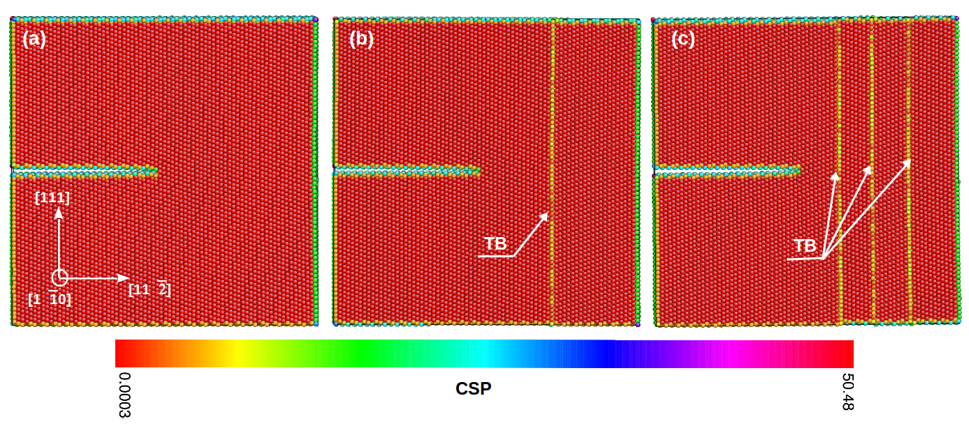
Initially, a single crystal BCC Fe oriented in , and [111] crystallographic directions has been created. Following this, an atomistically sharp crack was introduced on (111) plane with being the crack front direction i.e. the (111)110 crack (Figure 1a). The specimen had the dimensions of 1.6 nm 17.3 nm 17.3 nm. The crack length was half the width of the specimen i.e., 8.65 nm. In order to investigate the influence of TBs on the crack growth behaviour, single and multiple TBs were introduced perpendicular to the plane of crack as shown in Figure 1b-c. The periodic boundary conditions were applied only in the crack front direction, . The model systems was equilibrated to a temperature of 10 K in NVT ensemble with an integration time step of 2 fs. Upon completion of equilibrium process, the growth of an atomically sharp (111)110 crack has been studied in perfect (Figure 1a) as well twinned BCC Fe (Figure 1b-c) under mode-I loading employing the same NVT ensemble and time step. The loading has been applied at a constant engineering strain rate of s-1 by imposing velocity to atoms along the [111] axis that varied linearly from zero at the bottom fixed layer to a maximum value at the top layer. The average stress is calculated from the Virial expression zimmerman2004calculation .
3 Results and Discussion
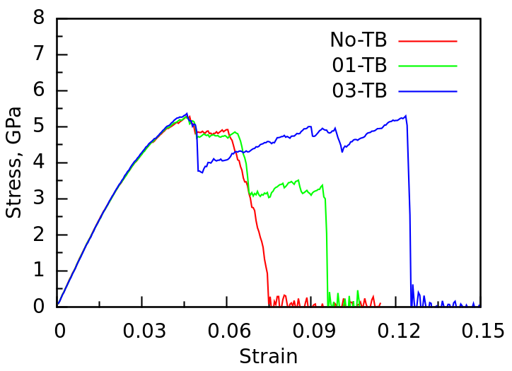
Figure 2 shows the stress-strain behaviour of pre-cracked perfect BCC Fe along with that of specimen containing one and three TBs perpendicular to the crack growth direction. It can be seen that during the elastic deformation, the stress-strain behaviour in all the samples is almost similar up to the peak value of stress. Following the elastic deformation, the flow stress shows a gradual drop from the peak value, which indicates the onset of crack growth. The stress drop is marginal in the case of perfect as well as sample with one TB, while significant drop is observed in sample with three TBs (Figure 2). Following the drop, the flow stress varies from sample to sample mainly due to their different internal microstructure, i.e., TBs. In perfect sample, the flow stress is constant up to certain value of strain and then rapidly falls to zero indicating the failure at a strain value of 0.075 (Figure 2). On the other hand, the flow stress in a sample containing a single TB shows an interesting step-wise decreasing behaviour, where the constancy over a period of strain is followed by a drop. Finally, it fails at a strain value of 0.10, which is relatively higher than the failure strain of perfect sample (Figure 2). In contrast, the flow stress of the sample containing three TBs shows a two-step gradually increasing behaviour before dropping to zero at a strain value of 0.122 (Figure 2). These results clearly show that increasing the number of TBs increases the plastic deformation and failure strain of BCC Fe.
In order to understand the mechanisms behind the role of TBs in increasing the failure strain of BCC Fe, the atomic configurations have been analyzed for pre-cracked perfect as well as twinned BCC Fe. Figure 3 shows the sequence of atomic snapshots displaying the growth of (111)110 crack in perfect BCC Fe without any TBs. It can be seen that the crack growth is initiated by the de-cohesion of atomic bonds on {110} plane (Figure 3a) followed by the nucleation of a micro-twin at the crack tip, which is orientated at from the crack plane (Figure 3b). With increasing strain, the crack changes its path from a single {110} plane to a combination of a small steps on two different {110} planes, which is effectively a {112} plane (Figure 3c). During this crack growth, many partial dislocations nucleate from the crack tip and glide on TBs leading to the growth as well as migration of a micro-twin (Figure 3c). This growth and migration of micro-twin is responsible for constant flow stress observed in the strain range 0.045 - 0.06 (Figure 2). Once the twin reaches certain critical thickness, the crack grows rapidly leading to the brittle failure (Figure 3d-f). In agreement with the present observation, previous reports have shown that the (111)110 crack system leads to brittle failure in BCC Fe gordon2007crack ; al2016atomistic . The brittle failure in this crack orientation is due to the lower energy release rate associated with cleavage ( than that of dislocation nucleation from a crack tip ( i.e., gordon2007crack .
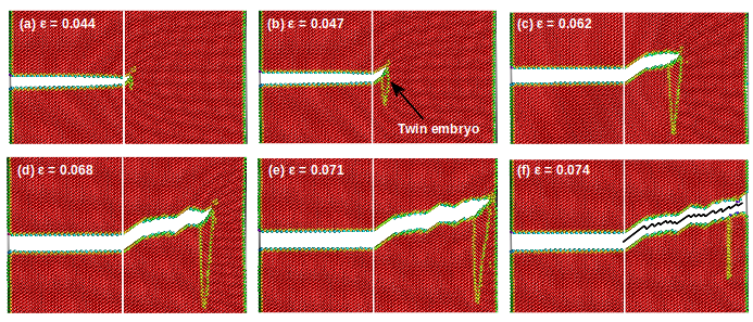
Figure 4(a-f) show the atomic snapshots depicting the growth of (111)110 crack in BCC Fe containing a single TB. Similar to perfect crystal, the crack grows in a brittle manner on {110} plane with a micro-twin at the crack tip (Figure 4a-b). However, once the crack tip reaches the TB, the micro-twin gets annihilated due to twin-twin interactions (Figure 4c). The annihilation of micro-twin relaxes the stress from 4.8 to 3 GPa (Figure 2). Following the annihilation of micro-twin, the 1/2111 full dislocations nucleate continuously from the intersection of crack tip and TB (Figure 4d) leading to significant plastic deformation. The continuous emission of dislocations blunts the crack, temporarily arresting the crack growth. Once the strain reaches certain critical value, the crack penetrates the TB and grows rapidly on a symmetric {110} plane leading to final failure (Figure 4e-f). Thus, it can be seen that the presence of TB introduces some plastic deformation which blunts the crack and in turn delays the brittle failure.
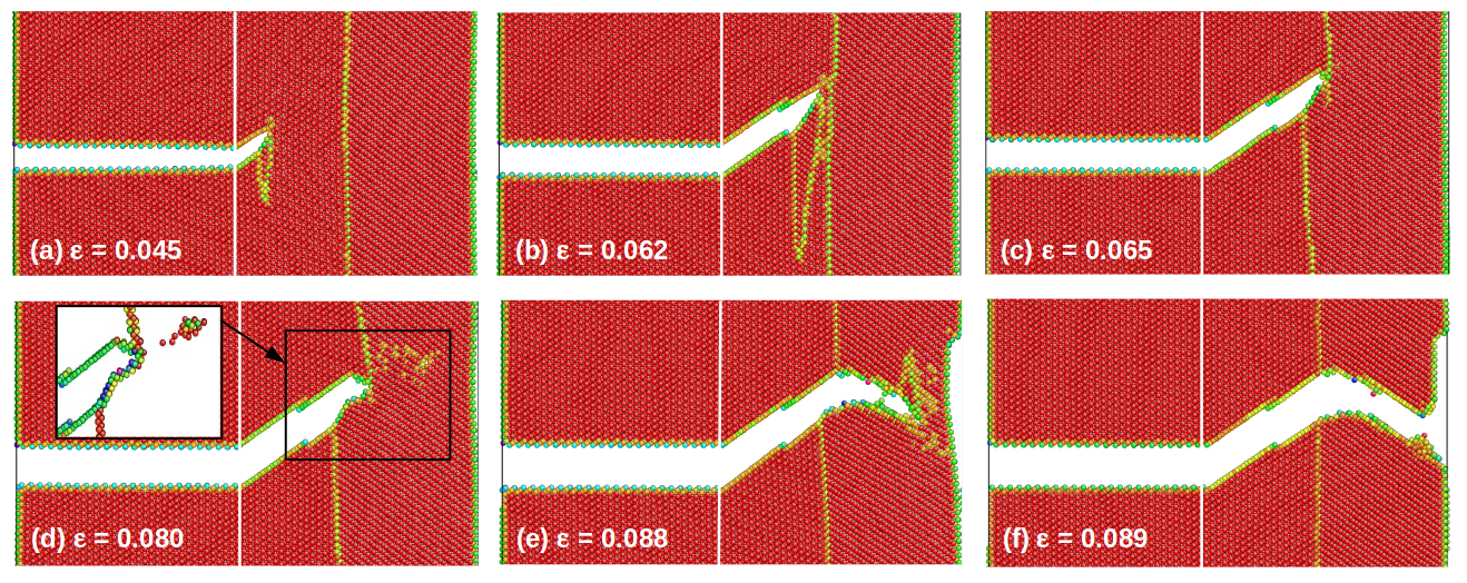
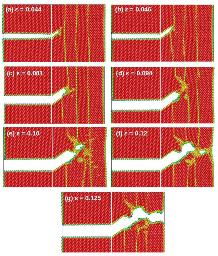
Figure 5 shows the atomic snapshots depicting the growth of (111)110 crack in BCC Fe containing multiple TBs. It can be seen that the crack grows in a brittle manner on {110} plane without any micro-twin at the crack tip (Figure 5a-b), suggesting that the presence of TBs close to the crack tip may suppress the formation of deformation twin at the tip of the crack. Once the crack tip reaches the TB, the crack gets blunted due to the emission of dislocations (Figure 5c). With increasing strain, more and more dislocations are emitted from the intersection of crack tip and TB. As a result, the first TB becomes curved in nature and interacts with the middle TB ahead of the crack tip (Figure 5d). With increasing deformation, a void nucleates in the next grain from the twin-twin intersection and merges with the initial crack leading to an increased length of crack (Figure 5e-f). The same process of void nucleation, growth and merging with preceding crack leads to the final failure as shown in Figure 5g. This shows that more the number of TBs more is the plastic deformation, which significantly delays the brittle failure.
For better understanding the crack growth behaviour, the crack length has been measured as a function of strain. Figure 6 shows the length of the crack as a function of strain in pre-cracked perfect BCC Fe along with twinned BCC Fe. The crack length is measured as the minimum distance between the initial and final positions of a crack tip. In the beginning stage, it can be seen that the crack growth rate increases with increasing the number of TBs until a strain value of 0.06. In other words, the initially crack growth rate is high to low for multiple to no TB case. This anomalous behaviour may be due to an attractive force of TB on the crack tip. The TBs generally exerts an attractive or repulsive force on dislocations and other defects chen2007repulsive ; deng2010repulsive ; guo2011repulsive ; sainath2021role . As can be seen in Figure 1a-c, in three TBs case, the TB is closure to the crack tip as compared to the case of sample with one TB. When the TB is closure to the crack tip, the higher attractive force may be responsible for the higher crack growth rate. As the distance between TB and crack tip increases, the attractive force may decreases accordingly, thus reducing the crack growth rate in sample with one TB/no TB. Above the strain value of 0.06, the crack growth rate continuously increases in perfect sample until failure, while in sample containing a TB, it slows down after the strain value of 0.07 or the crack length of 13.5 nm. This indicates that the presence of TB delays the crack growth rate in BCC Fe. Once the crack penetrates the TB at a strain value of 0.095, once again the crack grows rapidly leading to final failure. In contrast to the perfect and single TB sample, the crack grows rapidly in the beginning following which the crack length is almost constant until just before failure in sample containing three TBs. This indicates that increasing the number of TBs increases the crack growth resistance or decreases the crack growth rate in the sample.
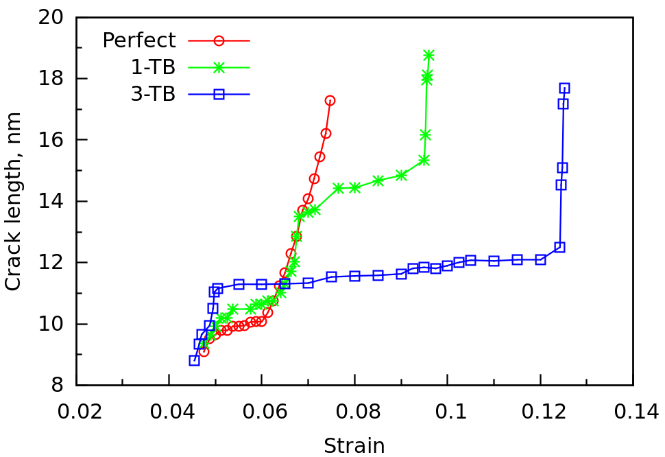
The comparison of Figure 6 with Figure 2 suggests an interesting relation between the crack growth rate and flow stress. It can be seen that, when the crack grows rapidly (high crack growth rate), a sudden drop in flow stress has been noticed. Similarly, when the crack grows gradually (crack growth rate increases linearly), the flow stress remains almost constant. On the other hand, when the crack growth rate is very small or negligible, the flow stress increases gradually. Similar relation between the flow stress and crack growth rate has been reported in Al fang2016molecular .
4 Conclusions
The influence of twin boundaries on the growth of an atomically sharp crack has been studied in BCC Fe using molecular dynamics simulations. The MD simulation results indicate that in perfect single crystal BCC Fe, the (111)110 crack system exhibits a brittle a behaviour, while in system containing TBs, the same crack system results in significant plastic deformation, which delays the brittle failure. Further, it has been observed that increasing the number of TBs increases the amount of plastic deformation leading to higher crack resistance or lower crack growth rates and higher strain to failure. The results on multiple twinned BCC Fe suggest that the presence of TBs close to the crack tip may suppress the formation of deformation twin at the crack tip. Finally, an interesting relationship has been observed between the crack growth rate and flow stress. When the crack grows rapidly (high crack growth rate), a sudden drop in flow stress is evident. Similarly, when the crack grows gradually (crack growth rate is linear), the flow stress remains almost constant. On the other hand, when the crack growth rate is very small or negligible, the flow stress increases gradually.
Conflict of interest
The authors declare that they have no conflict of interest.
References
- (1) L. Lu, X. Chen, X. Huang, K. Lu, Science 323(5914), 607 (2009)
- (2) X. Li, Y. Wei, L. Lu, K. Lu, H. Gao, Nature 464(7290), 877 (2010)
- (3) E. Qin, L. Lu, N. Tao, K. Lu, Scr. Mater. 60(7), 539 (2009)
- (4) A. Singh, L. Tang, M. Dao, L. Lu, S. Suresh, Acta Mater. 59(6), 2437 (2011)
- (5) L. Liu, J. Wang, S. Gong, S. Mao, Sci. rep. 4(1), 1 (2014)
- (6) C. Deng, F. Sansoz, Phys. Rev. B 81(15), 155430 (2010)
- (7) O. Anderoglu, A. Misra, H. Wang, X. Zhang, J. Appl. Phys. 103(9), 094322 (2008)
- (8) J. Wang, N. Li, A. Misra, Philos. Mag. 93(4), 315 (2013)
- (9) G. Sainath, B.K. Choudhary, Philos. Mag. 96(32-34), 3502 (2016)
- (10) S. Xu, J.K. Startt, T.G. Payne, C.S. Deo, D.L. McDowell, J. Appl. Phys. 121(17), 175101 (2017)
- (11) S. Xu, S.Z. Chavoshi, Y. Su, phys. stat. sol. (RRL)–Rapid Research Letters 12(3), 1700399 (2018)
- (12) L. Zhu, H. Ruan, X. Li, M. Dao, H. Gao, J. Lu, Acta Mater. 59(14), 5544 (2011)
- (13) Z. Zeng, X. Li, L. Lu, T. Zhu, Acta Mater. 98, 313 (2015)
- (14) X. Zhou, X. Li, C. Chen, Acta Mater. 99, 77 (2015)
- (15) S.W. Kim, X. Li, H. Gao, S. Kumar, Acta Mater. 60(6-7), 2959 (2012)
- (16) Y. Cheng, Z.H. Jin, Y. Zhang, H. Gao, Acta Mater. 58(7), 2293 (2010)
- (17) S. Plimpton, J. comput. phys. 117(1), 1 (1995)
- (18) M. Mendelev, S. Han, D. Srolovitz, G. Ackland, D. Sun, M. Asta, Philos. Mag. 83(35), 3977 (2003)
- (19) D. Terentyev, F. Gao, Mater. Sci. Eng. A 576, 231 (2013)
- (20) A. Kedharnath, A.S. Panwar, R. Kapoor, Comp. Mater. Sci. 137, 85 (2017)
- (21) G. Sainath, B.K. Choudhary, J. Appl. Phys. 122(9), 095101 (2017)
- (22) G. Sainath, B.K. Choudhary, Trans. Indian Inst. Met. 69(2), 525 (2016)
- (23) J. Li, Modell. Simul. Mater. Sci. Eng. 11(2), 173 (2003)
- (24) A. Stukowski, Modell. Simul. Mater. Sci. Eng. 18(1), 015012 (2009)
- (25) C.L. Kelchner, S. Plimpton, J. Hamilton, Phys. Rev. B 58(17), 11085 (1998)
- (26) J.A. Zimmerman, E.B. WebbIII, J. Hoyt, R.E. Jones, P. Klein, D.J. Bammann, Modell. Simul. Mater. Sci. Eng. 12(4), S319 (2004)
- (27) P.A. Gordon, T. Neeraj, M.J. Luton, D. Farkas, Metall. Mater. Trans. A 38(13), 2191 (2007)
- (28) A.T. Al-Motasem, N.T. Mai, S.T. Choi, M. Posselt, J. Nucl. Mater. 472, 20 (2016)
- (29) Z. Chen, Z. Jin, H. Gao, Phys. Rev. B 75(21), 212104 (2007)
- (30) C. Deng, F. Sansoz, Scr. Mater. 63(1), 50 (2010)
- (31) X. Guo, Y. Xia, Acta Mater. 59(6), 2350 (2011)
- (32) G. Sainath, P. Rohith, A. Nagesha, Comput. Mater. Sci. 197, 110564 (2021)
- (33) W. Fang, H. Xie, F. Yin, J. Li, Q. Fang, et al., Mater. Sci. Eng. A 666, 314 (2016)