Wideband Beamforming with Rainbow Beam Training using Reconfigurable True-Time-Delay Arrays for Millimeter-Wave Wireless
Abstract
The decadal research in integrated true-time-delay arrays have seen organic growth enabling realization of wideband beamformers for large arrays with wide aperture widths. This article introduces highly reconfigurable delay elements implementable at analog or digital baseband that enables multiple Spatial Signal Processing (SSP) functions including wideband beamforming, wideband interference cancellation, and fast beam training. Details of the beam-training algorithm, system design considerations, system architecture and circuits with large delay range-to-resolution ratios are presented leveraging integrated delay compensation techniques. The article lays out the framework for true-time-delay based arrays in next-generation network infrastructure supporting 3D beam training in planar arrays, low latency massive multiple access, and emerging wireless communications standards.
Index Terms:
True-time-delay array, array architecture, beam training, millimeter-wave communication, wideband systemsI Introduction
Wireless networks have fueled socio-economic growth worldwide and are expected to further advance to enable new applications such as autonomous vehicles, virtual and augmented reality, and smart cities. Due to shortage of sub- spectrum, millimeter-wave (mmW) frequencies play an important role in the fifth generation (5G) communication networks. Recent research and development of 5G mmW networks has revealed that the propagation loss in the mmW band [1] needs to be compensated by antenna array gain [2] and densification of base stations with cell radius as small as a hundred meters [3, 4]. To make radio chipsets power and cost- efficient, state of the art (SOTA) 5G mmW transceivers are designed with phased antenna array (PAA) based subarray architecture [5, 6]. As a consequence, signal processing techniques [7] and network protocols [8] for 5G mmW networks are designed under constraints of PAA architectures.

Future generations of mmW networks will operate in the upper mmW frequency band where more than bandwidth can be used to meet the ever-increasing demands [9, 10]. Their realization will demand addressing a completely new set of challenges including wider bandwidths, larger antenna array size, and higher cell density at the physical infrastructure level as highlighted in Fig. 1. These new system requirements demand fundamental rethinking of radio architectures, signal processing and networking protocols. Major breakthroughs are thus required in radio front-end architectures to enable wideband mmW networks, as most commonly adopted PAA based radios face many challenges in meeting the demanding requirements for different SSP functions.
A large portion of PAA implementations approximate the inter-element delay between the received signals with a phase-shift and hence the spatial processing is performed based on the phase difference between the received signals. This approximation simplifies the physical integrated circuit implementation, as compensating a phase shift is much simpler than a time delay. However, this simplification and approximation comes at the cost of limited operating fractional bandwidth of the receiver and will be analyzed further in Section II.
This article brings forward advances in true-time-delay (TTD) arrays that have the potential to significantly impact SSP for emerging wireless communication standards. We use TTD-based PAA [11, 12, 13, 14, 15, 16, 17, 18, 19, 20, 21, 22, 23, 24, 25, 26] to first establish a contrast with the current phase shift only PAAs [27, 28, 29, 30, 31, 32, 33, 34, 35, 36, 37, 38, 39, 40, 41, 42, 43, 44, 45] that will be used for both data communications and direction finding. The application of TTD-based PAAs for different SSP functions will have ramifications for future mmW network infrastructure and emerging wireless standards. We next develop a TTD-based PAA exploiting the so called beam squint phenomenon to achieve precision direction finding overcoming fundamental latency bottlenecks in earlier beam training methods.
II Exploiting Delay Compensation in Spatial Signal Processors

PAA operating over a very wide frequency band exhibits frequency-dependent beam pattern in an uncontrollable manner and it often degrades beamforming gain and directionality of the beam. This phenomenon is referred as spatial wideband effect [46] or beam squint [47, 48, 49], that becomes more significant in large antenna arrays.
This section will describe recent advances in SSP algorithms and architectures leveraging delay compensating circuits to overcome fundamental limits in analog PAAs. Interested readers are referred to [50] for a similar analysis for hybrid TTD PAAs. We will describe application of TTD arrays to realize different SSP modes when the array is used for data communications or for direction finding. In the former SSP mode, the TTD array will alleviate beam squint effects while in the latter mode, intentional beam squint is introduced to achieve accurate but fast beam-training significantly reducing the search latency in existing analog PAAs. To realize these different SSP modes in a TTD PAA, it is important to understand the trade-offs between the delay range, delay resolution, and modulated bandwidth as shown in Fig. 2. Higher delay resolutions and moderate bandwidth are needed for beam-nulling (independent interference cancellation [51]) whereas large delay range, moderate resolution, and large bandwidths are needed for beam-training. The SSP mode for independent interference cancellation is a corollary of the beamforming SSP and thus will not be studied in this article.
II-A Mitigating beam-squint for data communications mode
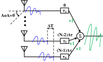
To alleviate the beam squint effect, the PAA is required to compensate inter-element signal delays before any SSP is done as illustrated in Fig. 3. Assuming a half-wavelength antenna spacing, the delay difference between the received signals in two consecutive antennas can thus be modeled as , which can be also expressed as a frequency-dependent phase shift difference in the frequency domain through the following expression:
| (1) |
where is frequency. If the signal of interest is narrowband, i.e., , the required TTD element can be replaced with a frequency-flat phase shifter (PS). This approximation is the basis of large portion of the SOTA SSP systems [28, 29, 30, 31, 32, 33, 35, 42, 38, 39, 40, 41, 43, 44, 34, 36, 37, 27, 19, 45]. A generalized implementation of phase shifting based SSP unit is shown in Fig. 4.
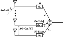
As for any approximation, replacing a TTD element with a PS imposes performance limitations. These limitations can be described both in the angular domain and the frequency domain. In the angular domain, PS-based implementation causes the intended angle-of-arrival (AoA) to be frequency-dependent. To be more specific, the intended AoA, for the both beamforming and beam-nulling cases, varies with the signal of interest frequency as in:
| (2) |
At the center frequency of the band, the PS-based and the TTD-based AoAs are the same and the beam is formed/nulled. As the frequency moves away from the center, the approximation of TTD with a PS becomes less valid and there will be an error between the actual and real intended AoA. This error can be formulated as follows:
| (3) |
This error depends on the actual AoA and the relative frequency of the interest. The maximum error happens at the edges of the frequency band, as the frequency deviates the most from the center frequency. As the error is inversely proportional to the frequency, at the lower side of the frequency band error will be larger than the higher side of the band and this maximum error can be found as:
| (4) |
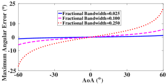
where is the signal bandwidth and is called the fractional bandwidth. In Fig. 5, the maximum error in the angular domain for a PS-based SSP unit is plotted versus the ideal intended AoA, for three cases of fractional bandwidths. In this plot the AoA range is limited to , since for larger AoAs the actual AoA can be as high as and the error in those cases does not reflect the severity of the PS-based implementation. As it can be seen, this error can get as high as which results in non-alignment with the intended transmitter and consequently loss in the desired signal (beamforming case) or imperfect cancellation (beam-nulling case). The frequency-dependent approximation of a TTD element with a PS results in frequency-dependent beamforming gain that acts as a bandpass filter [20, 22], and imperfect frequency-dependent beam-nulling that results in wideband interference leakage [51, 23].
The beamforming gain in a PS-based -element receiver can be modeled as the absolute value of the inner product , where is a receive beamformer and is a spatial response vector. Assuming a phase difference of between neighboring PSs, the -th element of is defined as . On the other hand, using (1), the -th element of is defined as . Expressed as a sum of complex exponentials, the gain becomes
| (5) |
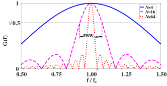
In Fig. 6, the normalized beamforming gain for intended AoA of versus normalized frequency of the input signal for three cases of , are plotted. The beamforming gain in a PS-based implementation acts as bandpass filter for the desired signal. Similar to a filter, the 3-dB fractional bandwidth () can be defined as the fractional bandwidth where the beamforming gain drops 3 dB compared to the maximum value (). As proven in [52, 53], for large values of N, the is given as:
| (6) |
For larger arrays becomes smaller and the approximation of a TTD element with a PS becomes less valid. Similar to the outcome of the beam squinting error, as the intended AoA increases, the gets smaller and the effective error increases.

II-B Beam-squint array for beam-training mode
Beam-training is a part of initial access (IA) protocol in mmW networks that achieve alignment of beamforming directions to realize a maximum gain between base station (BS) and user equipment (UE) [54, 55]. Beam-training using PAA requires extensive beam sweeping to estimate angle-of-departure (AoD) and AoA (Figure 7(a)), as it can only probe one steering direction at a time. As a result, PAA-based IA latency increases with array size and number of users [54]. The majority of existing mmW beam-training algorithms was designed for analog PAA due to their power efficiency. Phased arrays use frequency-flat PS in all antenna branches to steer/combine the signal in a desired direction. With a single mmW chain, PAAs can synthesize only one spatial beam with all frequency components being aligned in the same direction. The existing beam-training schemes with PAAs include various types of exhaustive beam sweeping where different beam candidates are sequentially used for channel probing to find the AoA [56, 57, 58, 59]. The required number of probing beams linearly scales with the number of antenna elements , thus, the beam-training overhead becomes a bottleneck for low-latency communications. SOTA IA approaches based on 5G requirements are limited to narrowband pilots and relatively small number of antennas, so the IA latency is acceptable. However, future evolutions of mmW-nets will be IA latency limited and would require using wideband pilots and new radio architectures that can probe a large number of AoA/AoD in parallel as illustrated in Figure 7(b).
To address this fundamental issue in mmW PAAs, this article will introduce a fast beam training method leveraging TTD arrays. Instead of suppressing the beam squint effect evident in mmW arrays, we will exploit this effect to our advantage by introducing intentionally large time delays in each antenna branch to realize frequency-dependent probing beams which can be exploited to accelerate the channel probing capability. These frequency-dependent beams will be fully controlled by adjusting the delay introduced in TTD circuits [60].
In summary, this article presents reconfigurable delay compensating circuits with large delay range and bandwidth, and finer delay resolution to realize wideband mmW SSP. Section III summarizes the TTD SSP architectures highlighting the challenges associated with realizing large delay compensation with fine resolution at different domains in the receiver chain. Section IV discusses the fast beam-training algorithm and practical design considerations for analog PAAs leveraging TTD SSP architecture. Section V will present the hardware implementation of reconfigurable time delay units enabling different SSP modes along with hardware validation methods for wideband PAAs. Section VI presents future works expanding the proposed TTD-based PAAs for beam-training with planar arrays, multiple access applications, and standardization of wireless protocols. Section VII concludes this article.
III Overview of mmW TTD PAAs
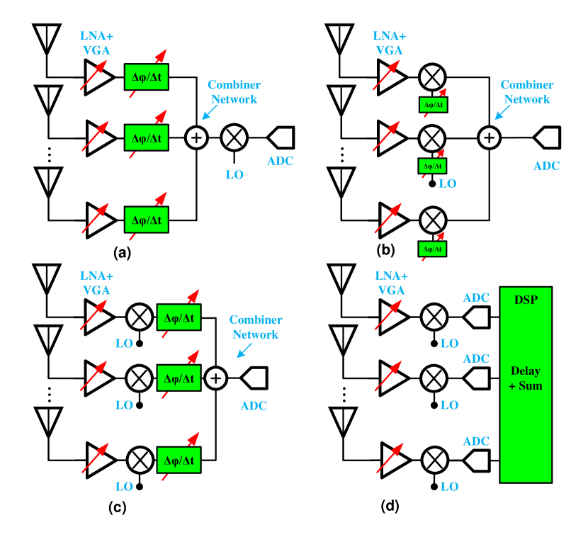
This section describes the possible architectural choices for TTD PAAs. The design of PAAs are based on two principles: (1) phase/delay alignment of signals either in transmit or receive path, and (2) summation of phase/delay aligned signals. To align the received signals in a PAA, delay elements should provide the proper delay to each received signal. The delay can be applied to the signal in mmW, LO, baseband, or digital domains. When the fractional bandwidth of the signal or the required delay range in the phased array system is small, the delay is approximated by a phase shift as discussed before. There are different topologies that are common in the implementation of PAA transceivers (Fig. 8) such as radio frequency (RF) phase shifting [61, 62, 63, 64], LO phase shifting [65, 66], baseband (BB) phase shifting [67, 68], and digital phase shifting [69]. In the RF phase-shifting architecture, after applying the required phase shift in each RF path, the signals can be combined together. LO phase shifting architecture uses the PS in the LO port of the mixer. In BB and digital phase-shifting architecture, the received signals are aligned after downconversion, using analog circuitry in baseband or in a digital processor. Either of these architectures is a good candidate when the signal’s fractional bandwidth is small, or the required delay range in the PAA is small.
![[Uncaptioned image]](/html/2111.15191/assets/x9.png)
![[Uncaptioned image]](/html/2111.15191/assets/x10.png)
For large delay-bandwidth product cases, delay units are necessary to prevent beam squint. Similar to a PS-based PAAs, the location of the time delay unit makes possible multiple architectures (mmW/RF path, LO port of the mixer, BB, or digital domains). In the mmW/RF TTD architecture, the time delay unit is placed in the mmW/RF domain before the downconversion. The received signals at each receiver path can be combined constructively, as shown in Fig. 8(a). The mixer is shared between multiple paths and only one LO signal is necessary which allows significant area and power reduction. As the signals are combined before downconversion, interferers are removed due to spatial filtering, which reduces the linearity requirements of the blocks after the combiner. Although there are different implementations of the mmW/RF TTD-based PAAs, these implementations occupy a large area on the chip and there are serious limitations on the delay range. Table I highlights the integrated mmW/RF TTD implementations over the past decade starting with the seminal work by Chu and Hashemi in 2007. Placing the TTD element in the LO path of the mixer does not resolve these limitations especially when handling wideband range. Digital TTD PAA is the same as a digital phased array and the challenges are the same such as high power consumption including the need for highly linear analog-to-digital converter (ADC) as well as other linear elements. However, there are promising TTD-based PAAs in BB with large delay-bandwidth products [22, 70]. Table II highlights recent SOTA TTD-based PAAs and delay lines implemented at BB.
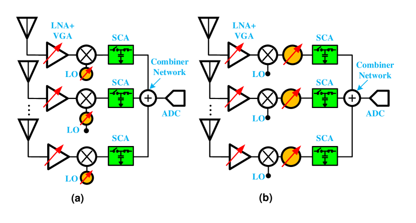
In an array with BB TTD elements as shown in Fig. 9 [22], instead of delaying the down-converted and phase shifted signals from the antennas followed by sampling and digitization, the signals are sampled at different time instants. Thus, the complexity of delaying signals is shifted to the clock path where precise and calibrated delays can be applied in the advanced semiconductor technology nodes. More importantly, a large delay range-to-resolution ratio can be easily realized while supporting a relatively larger number of antennas and bandwidth. The switched-capacitor adder based implementation requires multiple time-interleaved and delay compensated phases for formation of the beam [22]. In the sampling phase, the input signal from each channel is first sampled (with delayed time-interleaved clocks) on a sampling capacitor. After the last sampling phase, the stored charges on each capacitor corresponding to each channel (and each time-interleaved phase) are summed to form the beam. However, since time delay in BB is not mathematically equivalent to the time delay in the RF domain, a small phase shift is still necessary [20, 22]. For example, if a time delay of is needed, it can be implemented in the BB with a time delay equal to plus a phase shift equal to [37, 22, 20]. The BB TTD architecture shown in Fig. 9 is hereby referred as discrete-time TTD SSP.
A PS can be implemented in the RF, LO, BB, or digital domain to provide the required phase shift to the BB time delay units. The mmW/RF PS can be limited by the maximum delay-bandwidth product of the receiver. Digital implementation of the TTD or PS is similar to digital phase-shifting architecture with each RF path requiring an ADC which increases the power consumption of the whole system considerably. ADCs should be linear enough to tolerate the large interferences which further increases the whole system’s power consumption. Placing a PS in BB or LO is another feasible option (Fig. 9). In these architectures, each RF path has a dedicated mixer and an LO signal. PS in the LO port of the mixer should operate at the LO frequency. However, the PS in the BB or intermediate frequencies has to operate at lower frequencies. Though the loss and phase error of the PS in RF frequencies is higher than the PS at BB, the PS at the BB has to operate at a much higher fractional bandwidth while the PS in LO path only deals with a single tone signal (Fig. 9(a)). The PS can be implemented in the LO [71] as well as conventional PS architectures.
BB PS using vector summation is also another option. Vector summing PS is based on the weighted summation of quadrature signals. Quadrature signal generation is possible using a quadrature coupler, polyphase filters, or using quadrature mixers. Quadrature couplers at the BB occupies a large chip area and thus less preferred. Polyphase filters usually are narrow-band which contradicts with the large-delay bandwidth required. The use of quadrature downconversion mixers is another option though at the expense of routing complexities.
The next section presents the framework of leveraging discrete-time TTD SSP for fast beam-training followed by details on hardware implementation and experimental validation of TTD SSP.
IV Rainbow Beam-Training using Discrete-Time TTD SSP
This section describes the design of TTD array parameters, which enable a training codebook of frequency-dependent beams to be synthesized. We also explain the corresponding frequency-domain digital signal processing (DSP) algorithm [60]. We further discuss the practical aspects of TTD beam training including the sensitivity to hardware impairments, power allocation and the peak-to-average power ratio (PAPR) problem in orthogonal frequency-division multiplexing (OFDM) systems, and achievable beam training distance.
IV-A Introduction to Rainbow beam-training for mmW PAAs
Recent work on mmW and sub-THz beam-training has been focused on minimizing the required overhead using frequency-dependent beam steering/combining [72, 73, 13, 60, 74, 50]. The main idea is to leverage different antenna architectures that can synthesize rainbow beams to probe the entire angular range simultaneously. Each rainbow beam is associated with a different frequency, thus, information of the best steering/combining direction is embedded in the signal spectrum and it can be obtained through simple frequency-domain DSP. In [72], the authors proposed to use leaky wave antenna (LWA) for a single-shot AoA estimation. In [73], a delay-phase array architecture was proposed for fast beam tracking with rainbow beams at THz frequencies. TTD array architectures in [13] implemented delay elements in RF, which are known to suffer from low scalability in terms of required area and power efficiency when the array size becomes large. In our recent work in [60, 74, 50], we proposed a scalable TTD arrays with delay elements implemented in baseband for a single-symbol mmW beam training in an OFDM system. The key idea was to exploit signal delaying in each antenna branch to exacerbate the wideband spatial effect (beam squint) among subcarriers in a controllable manner, i.e., to create a frequency-dependent codebook which probes all angular directions at once. This is achieved by properly configuring the delay and phase taps in a TTD array.
IV-B TTD codebook and DSP algorithm design
In our recent work we introduced TTD-based beam-training at the UE side that requires only one OFDM symbol [60, 74, 50]. We assume that the BS with antennas uses a fixed frequency-flat precoder designed according to the previously estimated AoD. The received signal at the -th OFDM subcarrier can be expressed as follows
| (7) |
where is a frequency-dependent UE TTD combiner, is a channel matrix, is a pilot, and is a noise vector at the -th subcarrier, respectively. The -th element of is defined as
| (8) |
where , , and are the gain, delay tap, and phase tap in the -th antenna branch, respectively.
Assuming the bandwith and a uniform linear array (ULA) with a frequency-flat spatial response at the UE side, it was shown in [60] that a codebook of rainbow beams which cover the entire angular range can be created by setting the delay taps , as follows
| (9) |
Since the taps in (9) are proportional to the Nyquist sampling period, the codebook can be obtained without the need to implement a fractional ADC sampling. In such a codebook, the rainbow beam associated with the subcarrier frequency is pointing in the angle given as follows [60]
| (10) |
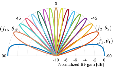
An example of the resulting TTD codebook for a UE with antenna elements is provided in Fig. 10. To probe directions, subcarriers need to be used. The codebook can be designed to be more robust in frequency-selective channels by mapping different subcarriers to each probed direction. This is achieved by increasing the delay difference between antenna elements times, i.e., [74]. With being the codebook diversity order and the number of probed directions, TTD beam training requires a waveform with loaded subcarriers.
| Symbol | Value | Description |
| 60 GHz | Carrier frequency | |
| 2 GHz | Bandwidth | |
| 4096 | Total number of subcarriers | |
| 128 | Number of BS antennas | |
| 16 | Number of UE antennas | |
| 32 | Number of probed directions | |
| 4 | Codebook diversity order | |
| () | 128 | Number of used subcarriers |
| 1024 | Dictionary size in [74] | |
| signal-to-noise ratio (SNR) | 0 dB | Signal-to-noise ratio |
The pointing angles , of rainbow beams can be jointly rotated by using the frequency-flat PSs in the TTD array. A rotation of requires the phase taps , to be set as follows
| (11) |
The rotated angles can then be expressed as .
With this codebook and described frequency-to-angle mapping, the information of the dominant propagation angle can be acquired with simple frequency-domain DSP. Given the received signal in (7), a coarse AoA estimate is given as , where the angle corresponds to the subcarrier with the strongest received signal power. Mathematically, the estimation can be expressed as
| (12) |
If the codebook diversity is , the power is averaged across all subcarriers mapped into the same direction before angle estimation.
The estimation accuracy can be improved by designing a high-resolution dictionary-based algorithm that relies on the codebook with diversity order [74]. The average received signal power in all probed directions can be correlated with an oversampled dictionary of UE beamforming gains to obtain an accurate angle estimate.
IV-C Practical considerations in TTD beam-training
IV-C1 Sensitivity to hardware impairments
In practice, errors in different hardware components can distort the delay taps in (9) and phase taps in (11) and thus affect the designed beam training codebook. We assume that delay errors can be modeled as Gaussian random variables, such that the distorted taps are , where is the error variance. The phase errors occur due to imperfect PSs, LOs, imbalance between in-phase and quadrature-phase samples, or other hardware errors. Similarly as with the delays, we model the distorted phase taps as , where is the error variance. In addition to the phase and delay errors, we consider distorted gain in all antennas branches. The gains are modeled with a log-normal distribution, i.e., .
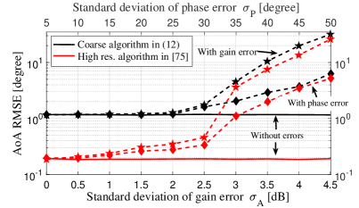
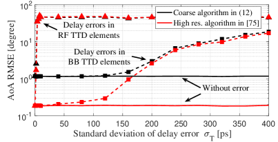
We have numerically evaluated the impact of all three hardware errors on the TTD beam training performance. Specifically, we compared the impact on two algorithms, including the coarse angle estimation algorithm introduced in the previous subsection and high-resolution algorithm in [74]. The assumed simulation parameters are summarized in Table III. In Fig. 11, we study the impact of gain and phase errors on the root mean square error (RMSE) of AoA estimation, under no delay error. For both algorithms, severe performance degradation occurs when the standard deviation of the gain error dB and phase error . In Fig. 12, the impact of TTD delay error is presented. With the proposed TDD architecture where time delay units are implemented in baseband, both algorithms are robust to delay errors with standard deviation of up to . In comparison, both algorithms start to show severe degradation with only in TDD architectures with RF time delay units studied in previous work [74]. This result indicates that both algorithms have more relaxed specifications for baseband implementation of TTD units compared to the RF TTD arrays.
IV-C2 Power allocation and supported distances
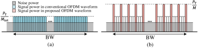
The proposed frequency-dependent beam-training uses an OFDM based waveform where only a subset of out of () subcarriers is loaded at the BS. This allows the transmit signal power to be allocated to a lower number of subcarriers, which can increase the SNR per subcarrier compared to that in conventional beam-training, as illustrated in Fig. 13. Specifically, when the total transmit power is divided among subcarriers, the SNR per subcarrier is given by the following expression
| (13) |
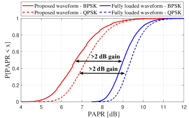
assuming a free-space path loss model. The terms , , , and represent the transmit beamforming gain, receive beamforming gain, wavelength, and distance between the BS and UE. Power spectral density of the noise is denoted as , while represents the subcarrier spacing. Note that the SNR per subcarrier is times larger than with a fully loaded OFDM waveform. Since the proposed DSP algorithm considers only loaded subcarriers with high SNR, angle estimation in (12) is not noise-limited. Further, due to a lower number of used subcarriers, the proposed OFDM waveform for TTD beam training results in a more than dB lower PAPR than a fully loaded OFDM waveform, as presented in Fig. 14, where we assumed the same simulation parameters as in the previous subsection. We used a cyclic prefix of 128 samples and assumed that subcarriers are loaded either with binary phase shift keying (BPSK) or quadrature phase shift keying (QPSK) symbols.
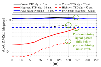
Although the proposed frequency-dependent beam-training can benefit from a higher SNR per subcarrier, the supported distances between the BS and UE are reduced compared to the PAA beam sweeping approach. This is because the UE has a lower total received signal power. Specifically, with the codebook in Fig. 10, which probes different directions, roughly of the signal power is received per direction. The received signal power corresponds to the subcarriers that probe the dominant AoA. To evaluate the impact of lower received signal power on the beam-training performance, we compared the AoA RMSE of TTD-based algorithms and PAA-based beam sweeping at different distances between the BS and UE. We assumed a non-line-of-sight scenario and modeled the path loss according to mmMAGIC channel [75]. We considered two array sizes at the UE, including and . With , directions are probed, while with , directions are probed. Other parameters are the same as in the previous subsection. The comparison results are presented in Fig. 15. PAA-based beam sweeping combines the entire signal bandwidth in each probed direction and thus achieves a high received signal power and reliable angle estimation at different distances. Nevertheless, it requires large overheads of and OFDM symbols to do so when and , respectively. On the other hand, TTD beam training algorithms are based on a single OFDM symbol and their performance is comparable to that of exhaustive PAA beam sweeping. However, supported distances in TTD beam-training are reduced, assuming that the signal cannot be detected when its total post-combining power falls below post-combining noise level. In our simulations, this happens at m for and m for , as highlighted in Fig. 15. We note that with a more sophisticated detection algorithm that exploits the waveform structure, beam training capabilities and supported distances of TTD arrays could increase. We leave a more detailed theoretical study of supported distances and better detection algorithms for future work.
V Reconfigurable Discrete-time TTD SSP Hardware Design Considerations
In this section, we describe the design and hardware implementation of reconfigurable time delay units in the discrete-time TTD SSP shown in Fig. 9 applied to both the data communications as well as beam-training SSP modes.
V-A Important sub-systems in discrete-time TTD SSP
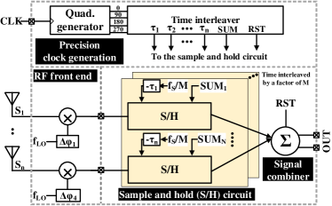
The analog array though more energy efficient when compared to hybrid TTD and digital arrays [50] require larger unity-gain bandwidth amplifiers to have similar performance. The circuit performance is further constrained with the parasitic capacitance, routing losses, crosstalk, and any possible mismatches during fabrication evident at multiple levels including silicon, packaging, or printed circuit board. Design considerations for the key blocks are described here to ensure low-power consumption is upheld for analog arrays as compared to hybrid or digital TTD SSP [50] including its ability to achieve fractional delays with high precision. This section presents design considerations for the key design blocks: (i) sample-and-hold, (ii) wideband signal combiners, and (iii) precision clock generation. Fig. 16 shows a more detailed illustration of the discrete-time TTD SSP. Interested readers can refer to [50, 26, 22, 51] for further understanding.
V-A1 Sample-and-hold
The design constraints for the input sample-and-hold draws parallel to the design requirements of a high-speed time-interleaved ADC [76]. Different interleaver configurations can be analyzed based on a simplified switch model in which the switch resistance and capacitance are linked to the technology. To reduce effect of sampling jitter, it is preferable to sample first followed by subsampling however at the cost of additional source followers which can significantly impact power consumption and linearity. To relax the power consumption, the first sampler can be interleaved (typically by 2 or 4) at the cost of slightly higher mismatch and jitter [77].
V-A2 Signal combiners
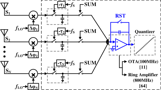
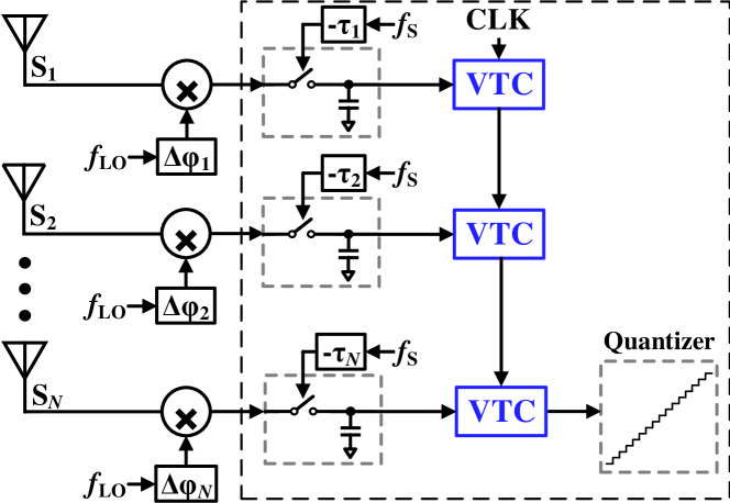
The signal combiner is a critical component for wideband discrete-time beamforming that requires careful design considerations of several parameters including gain, bandwidth, number of summing channels (each channel refers to a downconverted RF signal from each antenna element), dynamic range, and power consumption. The multi-parameter optimization considering the required design specifications for each system can be addressed using either a closed-loop or open-loop summing amplifiers, shown in Fig. 17(a). In [22], a closed-loop operational transconductance amplifier (OTA) is used whose design complexity and power consumption are scaled exponentially with the bandwidth. To support larger bandwidths and higher number of antennas, a closed loop integrator using ring amplifier [78, 79] was demonstrated in [26]. Ring amplifiers are technology scalable lending them good candidates to beamform signals from even larger number of antenna elements. In contrast to closed-loop amplifiers, summing can also be performed through daisy-chain linked voltage-to-time converter (VTC)s as shown in Fig. 17(b). The serialized VTCs each acting in open-loop is digitized by a multi-bit time-to-digital converter (TDC) creating an equivalent of matrix-multiplying ADC.
V-A3 Precision clock generation
The required sampling phases of the discrete-time SSP can be generated on-chip as illustrated in [22, 26]. To achieve higher precision and matching following Nyquist criterion as well as use the same architecture for different SSP modes, the clock generation requires N low-power precision phase interpolator (PI) and time-interleavers [51, 22, 50]. The time-interleaver output is applied to interleaved multiply-and-accumulate units that enables them to span the required delay range while meeting the Nyquist bandwidth.
High precision linear PSs are desired to meet the delay range and resolution requirements for the switched-capacitor array as discussed in Section III. Recent works have demonstrated PIs as digital-to-phase generator in different applications including clock-and-data recovery [80, 81] and outphasing transmitters [82, 83]. In general, several architectures have been proposed to implement PI which generates output of phases of weighted sum of two input clock phases based on the digital input code.
The underlying concept of PI can be studied from [84] which describes the process as addition of two phase-shifted edges to produce a new edge with the transition in between them. The output is a superposition of two exponential curves formed by the merged driver output resistance and the capacitive load. The linearity of the PI not only depends on the time difference between the input signals but also their rise times. It has been observed that the non-linearity for a step input response is more whereas it is less for the inputs with finite rise time inputs.
The current-steering digital-to-analog converter (DAC) have been popular architectures for implementing PI [85]. However, the linearity and resolution are greatly impacted by the DAC. As mentioned above, to generate finite rise time at the input, a slew rate control buffer is implemented which requires additional power. The summation of the direct in-phase and quadrature-phase however causes nonlinearity with respect to the codes. Alternatively, current-mode logic based PI architectures can be adopted if the inputs are sinusoidal signals. Instead of interpolating between two consecutive quadrature phases, it can be done in multiple cascaded stages. Interpolation between signals with small phase differences () is more linear than direct interpolation between the quadrature inputs. Though the current-mode logic based PI has lower swing which consumes less dynamic power, it suffers from linearity issue where as the inverter-based PIs suffers from high dynamic power. Additionally, the PI’s output gets affected by the power supply variations. Low-dropout regulators can be applied between the main power supply and the PI supply to alleviate this issue. As such, its important to consider the design trade-offs for PIs specifically linearity and power consumption.
V-B Multi-antenna testbed and validation
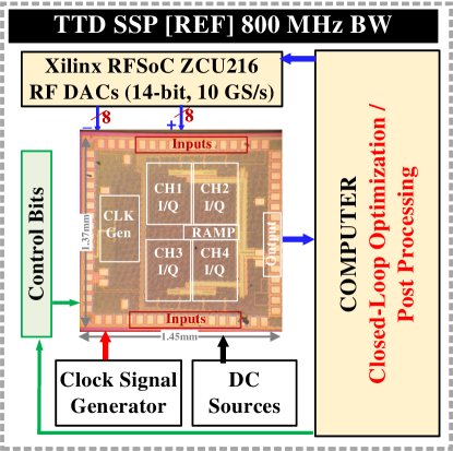
Another important step in the design process is developing the test interface between the mmW front-end and the BB TTD SSP as well as the digital back-end. The wide modulated bandwidths and the large number of downconverted channels from mmW to baseband due to both differential and quadrature configurations challenges the signal generation and post-processing. In addition, all the channels should be sychronized in time with picosecond accuracies to enable efficient data communications. Fig. 18 shows a sample closed-loop testbed for 800 MHz TTD SSP recently demonstrated in [26]. High speed DACs and ADCs in ZCU RFSoC family make it possible to generate wideband signals from DACs and perform data capture from the high speed ADC through the same graphic user interface control which serves both as an arbitrary waveform generator and spectrum analyzer in [22]. In [26], 800 MHz modulated bandwidth with 16 synchronized channels was generated and the outputs post-processed after digitization in MATLAB offline.
Besides synchronization and large number of channels, repeated parameterized sweeps across frequencies and angles to characterize a multi-antenna transceiver undertakes significant efforts without closed-loop automation in place. In [23], the TTD SSP (in particular, TDC and the time amplifiers) were optimized using particle swarm optimization techniques from [86]. While the optimization was limited to TDC only and not the entire SSP, this method shows the potential opportunities to further extend the test bench automation for closed-loop signal path optimization.
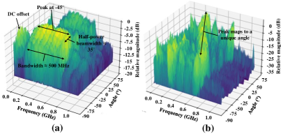
In their recent work, the authors have used computer vision techniques for testbed automation in [87]. These techniques reduces the strenuous manual calibration and test process significantly and enables generation of data-intensive 3D plots (Fig. 19(a)) and frequency-angular maps (Fig. 19(b)) that can be used to create accurate dictionaries for calibration in data communications mode. The shown plots represent 72 individual configurations when the 4-element array is configured to -45∘ with 500 MHz modulated bandwidth at the input. The measured half-power beamwidth is close to the theoretical estimated 35∘. Similar map can be generated for the rainbow beam-training as shown in Fig. 19(b) which shows the efficacy of the proposed algorithm. Additional measurement details for these plots are captured in [87]. The automated test process further minimizes the human errors in the manual process. In addition, this enables benchmarking entire system from the antenna to the higher network layers combined with machine learning algorithms in future.
VI Future Work
VI-A 3D rainbow beam with planar TTD array
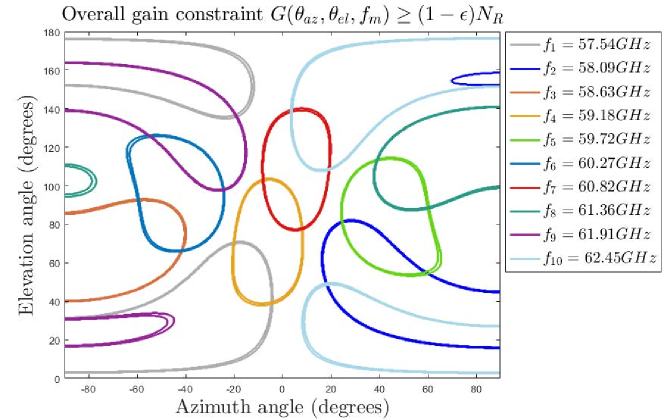
In principle, the frequency dependent beam steering can be extended into the planar TTD array. In our recent work [88] we studied beamforming codebooks with the uniform delay steps , introduced in the antenna elements in the x-y plane before combining, i.e., the received signal in the -th element is delayed by . We showed that uniform delay spacing can create 3D beams such that different frequency components are steered toward a unique spherical direction . Further, the entire 3D angular space can be covered by at least one beam. Fig. 20 presents the frequency dispersing steering for 10 frequency components. However, this preliminary study also reveals a number of design challenges from both circuits and system perspectives. On the one hand, the required maximum delay range is increased. For planar array with a total elements, the required delay range is at least , a factor of 2 larger than its linear array counterpart. On the other hand, as compared to the rainbow beam using a linear TTD array, the 3D rainbow beam using planar array has some unique characteristics. More specifically, beams from some frequency component experience a reduced gain as compared to others. There is non-trivial challenge to calibrate the beam pattern and design beam training algorithm tailored for this non-ideality.
VI-B TTD rainbow beam enabled multiple access
The beam training is not the only application of the TTD array dispersive rainbow beam. In [89], a novel orthogonal frequency division multiple access scheme is proposed. Utilizing a TTD array at the network infrastructure, different frequency resources are steered toward different unique directions to serve users. There are a number of advantages that make such scheme appealing for the future IoT application. Firstly, the hardware bandwidth of each user can be much smaller than the infrastructure, because each of them only access a portion of the frequency. This facilitates a power and cost friendly design for the terminals. Secondly, the conventional time division beam switching can be eliminated, because different users are simultaneously served using different frequency resource implicitly allocated by their corresponding rainbow beam direction. It further brings the potential to reduce the beam management overhead to support IoT applications with strict latency requirements [89]. However, the challenge remains for the device to precisely synchronize with the network in frequency, because rainbow beam heavily relies on the mapping between frequency and beams. To this end, a frame structure and synchronization procedure that is compatible with existing standard is critical.
VI-C Compatibility of TTD Beam Training with 5G Standard
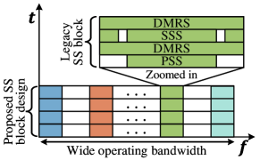
Exhaustive beam sweeping with synchronization is the main part of the IA procedure in 5G New Radio Standard. It is performed using periodic bursts of up to 64 SS blocks, each associated with a different steering direction [55]. An SS block is a group of 4 consecutive OFDM symbols with 240 subcarriers ( resource blocks) that carry the Primary Synchronization Signal (PSS), Secondary Synchronization Signal (SSS), and DeModulation Reference Signal (DMRS). The PSS and SSS are leveraged for synchronization between the BS and UE, while the DMRS can be used to estimate the received power associated with that direction, i.e., SS block.
Since the proposed TTD beam training is fundamentally different from beam sweeping, its compatibility with the current 5G New Radio Standard becomes an important problem. In our preliminary work, we proposed a different design of the SS block, which exploits wide available bandwidth at mmW frequencies and supports TTD beam training, as illustrated in Fig. 21. In the proposed design, the existing reference signals are repeated multiple times across the operating bandwidth. With such training waveform, the UE is capable of receiving at least one entire legacy SS block using its frequency-dependent beam steering. The UE can then leverage DSP to extract the reference signals to achieve synchronization with the BS and determine the best steering direction. The proposed SS block design removes the need for SS bursts and thus minimizes the required overhead in TTD beam training. However, the design depends on different system parameters, including the number of subcarriers, number of UE antennas, and resolution of UE beam probing. We plan to address these practical design questions in our future work.
VII Conclusions
Reconfigurable TTD arrays are essential for emerging mmW wireless communications demanding wide bandwidths with ultra-low-latency in direction finding compared to current wireless standards. This magazine article presents a comprehensive overview of the recent developments in TTD arrays enabling multiple SSP functions. Delay compensation techniques are exploited to prevent beam squint during data communications while introducing intentional beam squint for fast beam-training. The article combines the beam-training algorithm with the underlying architectural and circuit design considerations. The exciting developments in TTD arrays presented herein lays out a future path for enabling next-generation network and physical infrastructure wireless solutions on a large-scale with 3D direction finding for communications-on-the-move applications, massive machine type communications, and standardization in emerging wireless standards.
References
- [1] A. Ghosh et al., “Millimeter-wave enhanced local area systems: A high-data-rate approach for future wireless networks,” IEEE J. Sel. Areas Commun., vol. 32, no. 6, pp. 1152–1163, Jun. 2014.
- [2] T. S. Rappaport et al., “Millimeter wave mobile communications for 5G cellular: It will work!” IEEE Access, vol. 1, pp. 335–349, May 2013.
- [3] R. Baldemair et al., “Ultra-dense networks in millimeter-wave frequencies,” IEEE Communications Magazine, vol. 53, no. 1, pp. 202–208, January 2015.
- [4] N. Bhushan, J. Li, D. Malladi, R. Gilmore, D. Brenner, A. Damnjanovic, R. T. Sukhavasi, C. Patel, and S. Geirhofer, “Network densification: the dominant theme for wireless evolution into 5G,” IEEE Commun. Mag., vol. 52, no. 2, pp. 82–89, Feb. 2014.
- [5] V. Raghavan et al., “Millimeter-wave MIMO prototype: Measurements and experimental results,” IEEE Communications Magazine, vol. 56, no. 1, pp. 202–209, Jan 2018.
- [6] Y. Huang, Y. Li, H. Ren, J. Lu, and W. Zhang, “Multi-panel mimo in 5g,” IEEE Communications Magazine, vol. 56, no. 3, pp. 56–61, March 2018.
- [7] R. W. Heath et al., “An overview of signal processing techniques for millimeter wave MIMO systems,” IEEE J. STSP, vol. 10, no. 3, pp. 436–453, Apr. 2016.
- [8] H. Shokri-Ghadikolaei, C. Fischione, G. Fodor, P. Popovski, and M. Zorzi, “Millimeter wave cellular networks: A MAC layer perspective,” IEEE Transactions on Communications, vol. 63, no. 10, pp. 3437–3458, Oct 2015.
- [9] P. Yang, Y. Xiao, M. Xiao, and S. Li, “6g wireless communications: Vision and potential techniques,” IEEE Network, vol. 33, no. 4, pp. 70–75, July 2019.
- [10] Z. Zhang, Y. Xiao, Z. Ma, M. Xiao, Z. Ding, X. Lei, G. K. Karagiannidis, and P. Fan, “6g wireless networks: Vision, requirements, architecture, and key technologies,” IEEE Vehicular Technology Magazine, vol. 14, no. 3, pp. 28–41, Sep. 2019.
- [11] R. Rotman, M. Tur, and L. Yaron, “True time delay in phased arrays,” Proc. IEEE, vol. 104, no. 3, pp. 504––518, 2016–03.
- [12] T.-S. Chu, J. Roderick, and H. Hashemi, “An integrated ultra-wideband timed array receiver in 0.13 cmos using a path-sharing true time delay architecture,” IEEE Journal of Solid-State Circuits, vol. 42, no. 12, pp. 2834–2850, 2007.
- [13] H. Hashemi, T. Chu, and J. Roderick, “Integrated true-time-delay-based ultra-wideband array processing,” IEEE Communication. Mag, vol. 46, no. 9, pp. 162––172, Sep. 2008.
- [14] T. Chu and H. Hashemi, “True-time-delay-based multi-beam arrays,” IEEE Transactions Microw. Theory Tech, vol. 61, no. 8, pp. 3072––3082, Aug. 2013.
- [15] S. Garakoui, E. Klumperink, B. Nauta, and F. van Vliet, “Compact cascadable gm-C all-pass true-time-delay cell with reduced delay variation over frequency,” IEEE Journal of Solid-State Circuits, vol. 50, no. 3, pp. 693––703, Mar. 2015.
- [16] F. Hu and K. Mouthaan, “A 1–20 GHz 400 ps true-time delay with small delay error in 0.13 µm CMOS for broadband phased array antennas,” in IEEE MTT-S International Microwave Symposium, May 2015, pp. 1–3.
- [17] M. Cho, I. Song, and J. D. Cressler, “A true time delay-based sige bi-directional t/r chipset for large-scale wideband timed array antennas,” in 2018 IEEE Radio Frequency Integrated Circuits Symposium (RFIC), 2018, pp. 272–275.
- [18] S. Jang, R. Lu, J. Jeong, and M. P. Flynn, “A true time delay 16-element 4-beam digital beamformer,” in 2018 IEEE Radio Frequency Integrated Circuits Symposium (RFIC), June 2018, pp. 12–15.
- [19] S. Mondal, R. Singh, A. I. Hussein, and J. Paramesh, “A 25–30 GHz fully-connected hybrid beamforming receiver for MIMO communication,” IEEE Journal of Solid-State Circuits, vol. 53, no. 5, pp. 1275–1287, 2018.
- [20] S. Jang, R. Lu, J. Jeong, and M. P. Flynn, “A 1-GHz 16-element four-beam true-time-delay digital beamformer,” IEEE Journal of Solid-State Circuits, vol. 54, no. 5, pp. 1304–1314, 2019.
- [21] M. B. Dastjerdi, S. Jain, N. Reiskarimian, A. Natarajan, and H. Krishnaswamy, “28.6 full-duplex 2×2 MIMO circulator-receiver with high TX power handling exploiting MIMO RF and shared-delay baseband self-interference cancellation,” in IEEE International Solid- State Circuits Conference (ISSCC), 2019, pp. 448–450.
- [22] E. Ghaderi et al., “An integrated discrete-time delay-compensating technique for large-array beamformers,” IEEE Transactions on Circuits and Systems I: Regular Papers (TCAS-I), vol. 66, no. 9, pp. 3296–3306, Sep. 2019.
- [23] ——, “10.8 A 4-element 500MHz-modulated-BW 40mW 6b 1GS/s analog-time-to-digital-converter-enabled spatial signal processor in 65nm CMOS,” in 2020 IEEE International Solid-State Circuits Conference (ISSCC), Feb. 2020.
- [24] K. Spoof, M. Zahra, V. Unnikrishnan, K. Stadius, M. Kosunen, and J. Ryynänen, “A 0.6–4.0 ghz rf-resampling beamforming receiver with frequency-scaling true-time-delays up to three carrier cycles,” IEEE Solid-State Circuits Letters, vol. 3, pp. 234–237, 2020.
- [25] E. Ghaderi and S. Gupta, “A four-element 500-MHz 40-mW 6-bit ADC-enabled time-domain spatial signal processor,” IEEE Journal of Solid-State Circuits, vol. 56, no. 6, pp. 1784–1794, 2021.
- [26] C.-C. Lin et al., “A 4-element 800mhz-bw 29mw true-time-delay spatial signal processor enabling fast beam-training with data communications,” in ESSCIRC 2021 - IEEE 47th European Solid State Circuits Conference (ESSCIRC), 2021, pp. 287–290.
- [27] J. Paramesh, R. Bishop, K. Soumyanath, and D. Allstot, “A four-antenna receiver in 90-nm CMOS for beamforming and spatial diversity,” IEEE Journal of Solid-State Circuits, vol. 40, no. 12, pp. 2515–2524, 2005.
- [28] A. Hajimiri, H. Hashemi, A. Natarajan, X. Guan, and A. Komijani, “Integrated phased array systems in silicon,” Proceedings of the IEEE, vol. 93, no. 9, pp. 1637–1655, 2005.
- [29] A. Natarajan, A. Komijani, and A. Hajimiri, “A fully integrated 24-GHz phased-array transmitter in CMOS,” IEEE Journal of Solid-State Circuits, vol. 40, no. 12, pp. 2502–2514, 2005.
- [30] A. Natarajan, A. Komijani, X. Guan, A. Babakhani, and A. Hajimiri, “A 77-GHz phased-array transceiver with on-chip antennas in silicon: Transmitter and local LO-path phase shifting,” IEEE Journal of Solid-State Circuits, vol. 41, no. 12, pp. 2807–2819, 2006.
- [31] S. Jeon, Y.-J. Wang, H. Wang, F. Bohn, A. Natarajan, A. Babakhani, and A. Hajimiri, “A scalable 6-to-18 GHz concurrent dual-band quad-beam phased-array receiver in CMOS,” IEEE Journal of Solid-State Circuits, vol. 43, no. 12, pp. 2660–2673, 2008.
- [32] H. Krishnaswamy and H. Hashemi, “A 4-channel 4-beam 24-to-26GHz spatio-temporal RAKE radar transceiver in 90nm CMOS for vehicular radar applications,” in IEEE International Solid-State Circuits Conference - (ISSCC), 2010, pp. 214–215.
- [33] A. Valdes-Garcia et al., “A fully integrated 16-element phased-array transmitter in SiGe BiCMOS for 60-GHz communications,” IEEE Journal of Solid-State Circuits, vol. 45, no. 12, pp. 2757–2773, 2010.
- [34] M. C. M. Soer, E. A. M. Klumperink, B. Nauta, and F. E. van Vliet, “Spatial interferer rejection in a four-element beamforming receiver front-end with a switched-capacitor vector modulator,” IEEE Journal of Solid-State Circuits, vol. 46, no. 12, pp. 2933–2942, 2011.
- [35] A. Natarajan et al., “A fully-integrated 16-element phased-array receiver in SiGe BiCMOS for 60-GHz communications,” IEEE Journal of Solid-State Circuits, vol. 46, no. 5, pp. 1059–1075, 2011.
- [36] M. Soer, E. Klumperink, B. Nauta, and F. van Vliet, “A 1.5-to-5.0GHz input-matched +2dBm P1dB all-passive switched-capacitor beamforming receiver front-end in 65nm CMOS,” in 2012 IEEE International Solid-State Circuits Conference, 2012, pp. 174–176.
- [37] A. Ghaffari, E. A. M. Klumperink, F. van Vliet, and B. Nauta, “A 4-element phased-array system with simultaneous spatial- and frequency-domain filtering at the antenna inputs,” IEEE Journal of Solid-State Circuits, vol. 49, no. 6, pp. 1303–1316, 2014.
- [38] H. Krishnaswamy and L. Zhang, “Analog and RF interference mitigation for integrated MIMO receiver arrays,” Proceedings of the IEEE, vol. 104, no. 3, pp. 561–575, 2016.
- [39] L. Zhang, A. Natarajan, and H. Krishnaswamy, “Scalable spatial notch suppression in spatio-spectral-filtering MIMO receiver arrays for digital beamforming,” IEEE Journal of Solid-State Circuits, vol. 51, no. 12, pp. 3152–3166, 2016.
- [40] L. Zhang and H. Krishnaswamy, “Arbitrary analog/rf spatial filtering for digital mimo receiver arrays,” IEEE Journal of Solid-State Circuits, vol. 52, no. 12, pp. 3392–3404, 2017.
- [41] M.-Y. Huang, T. Chi, F. Wang, and H. Wang, “An all-passive negative feedback network for broadband and wide field-of-view self-steering beam-forming with zero DC power consumption,” IEEE Journal of Solid-State Circuits, vol. 52, no. 5, pp. 1260–1273, 2017.
- [42] M. Johnson et al., “A 4-element 28 GHz millimeter-wave MIMO array with single-wire interface using code-domain multiplexing in 65 nm CMOS,” in IEEE Radio Frequency Integrated Circuits Symposium (RFIC), 2019, pp. 243–246.
- [43] M. Huang and H. Wang, “21.2 A 27-to-41GHz MIMO receiver with N-input-N-output using scalable cascadable autonomous array-based high-order spatial filters for instinctual full-FoV multi-blocker/signal management,” in IEEE International Solid-State Circuits Conference (ISSCC), 2019, pp. 346–348.
- [44] M.-Y. Huang and H. Wang, “A mm-wave wideband MIMO RX with instinctual array-based blocker/signal management for ultralow-latency communication,” IEEE Journal of Solid-State Circuits, vol. 54, no. 12, pp. 3553–3564, 2019.
- [45] S. Mondal and J. Paramesh, “A reconfigurable 28-/37-GHz MMSE-adaptive hybrid-beamforming receiver for carrier aggregation and multi-standard MIMO communication,” IEEE Journal of Solid-State Circuits, vol. 54, no. 5, pp. 1391–1406, 2019.
- [46] B. Wang, F. Gao, S. Jin, H. Lin, and G. Y. Li, “Spatial- and frequency-wideband effects in millimeter-wave massive MIMO systems,” IEEE Transactions on Signal Processing, vol. 66, no. 13, pp. 3393–3406, July 2018.
- [47] M. Cai, “Modeling and mitigating beam squint in millimeter wave wireless communication,” Ph.D. dissertation, University of Notre Dame, 2018.
- [48] B. Wang et al., “Spatial-wideband effect in massive MIMO with application in mmWave systems,” IEEE Commun. Mag., vol. 56, no. 12, pp. 134–141, Dec. 2018.
- [49] X. Liu and D. Qiao, “Space-time block coding-based beamforming for beam squint compensation,” IEEE Wireless Communications Letters, vol. 8, no. 1, pp. 241–244, Feb 2019.
- [50] V. Boljanovic et al., “Fast beam training with true-time-delay arrays in wideband millimeter-wave systems,” IEEE Transactions on Circuits and Systems I: Regular Papers, vol. 68, no. 4, pp. 1727–1739, 2021.
- [51] E. Ghaderi et al., “Four-element wide modulated bandwidth MIMO receiver with 35 dB interference cancellation,” IEEE Transactions on Microwave Theory and Techniques (TMTT), vol. 68, no. 9, pp. 3930–3941, 2020.
- [52] R. J. Mailloux, Phased Array Antenna Handbook, Second Edition, 2nd ed. Boston: Artech Print on Demand, Mar. 2005.
- [53] “Electromagnetic Waves and Antennas.” [Online]. Available: https://www.ece.rutgers.edu/~orfanidi/ewa/
- [54] H. Yan and D. Cabric, “Compressive initial access and beamforming training for millimeter-wave cellular systems,” IEEE Journal of Selected Topics in Signal Processing, vol. 13, no. 5, pp. 1151–1166, Sep. 2019.
- [55] M. Giordani, M. Polese, A. Roy, D. Castor, and M. Zorzi, “A tutorial on beam management for 3GPP NR at mmWave frequencies,” IEEE Communications Surveys Tutorials, vol. 21, no. 1, pp. 173–196, 2019.
- [56] C. Jeong, J. Park, and H. Yu, “Random access in millimeter-wave beamforming cellular networks: issues and approaches,” IEEE Communications Magazine, vol. 53, no. 1, pp. 180–185, 2015.
- [57] J. Kim and A. F. Molisch, “Fast millimeter-wave beam training with receive beamforming,” Journal of Communications and Networks, vol. 16, no. 5, pp. 512–522, 2014.
- [58] K. Hosoya et al., “Multiple sector ID capture (MIDC): A novel beamforming technique for 60-GHz band multi-Gbps WLAN/PAN systems,” IEEE Transactions on Antennas and Propagation, vol. 63, no. 1, pp. 81–96, 2015.
- [59] L. Zhou and Y. Ohashi, “Efficient codebook-based MIMO beamforming for millimeter-wave WLANs,” in 2012 IEEE 23rd International Symposium on Personal, Indoor and Mobile Radio Communications - (PIMRC), 2012, pp. 1885–1889.
- [60] H. Yan, V. Boljanovic, and D. Cabric, “Wideband millimeter-wave beam training with true-time-delay array architecture,” in 2019 53rd Asilomar Conference on Signals, Systems, and Computers, 2019, pp. 1447–1452.
- [61] M. Sayginer and G. M. Rebeiz, “An eight-element 2–16-ghz programmable phased array receiver with one, two, or four simultaneous beams in sige bicmos,” IEEE Transactions on Microwave Theory and Techniques, vol. 64, no. 12, pp. 4585–4597, 2016.
- [62] A. Nafe, M. Sayginer, K. Kibaroglu, and G. M. Rebeiz, “2 64-element dual-polarized dual-beam single-aperture 28-GHz phased array with 2 30 Gb/s links for 5G polarization MIMO,” IEEE Transactions on Microwave Theory and Techniques, vol. 68, no. 9, pp. 3872–3884, 2020.
- [63] B. Sadhu et al., “A 28-GHz 32-element TRX phased-array IC with concurrent dual-polarized operation and orthogonal phase and gain control for 5G communications,” IEEE Journal of Solid-State Circuits, vol. 52, no. 12, pp. 3373–3391, 2017.
- [64] J. D. Dunworth et al., “A 28GHz bulk-CMOS dual-polarization phased-array transceiver with 24 channels for 5G user and basestation equipment,” in 2018 IEEE International Solid-State Circuits Conference - (ISSCC), 2018, pp. 70–72.
- [65] J. Pang et al., “A 28-GHz CMOS phased-array transceiver based on LO phase-shifting architecture with gain invariant phase tuning for 5G new radio,” IEEE Journal of Solid-State Circuits, vol. 54, no. 5, pp. 1228–1242, 2019.
- [66] Y. Wang et al., “A 39-GHz 64-element phased-array transceiver with built-in phase and amplitude calibrations for large-array 5G NR in 65-nm CMOS,” IEEE Journal of Solid-State Circuits, vol. 55, no. 5, pp. 1249–1269, 2020.
- [67] G. Mangraviti et al., “13.5 a 4-antenna-path beamforming transceiver for 60GHz multi-Gb/s communication in 28nm CMOS,” in IEEE International Solid-State Circuits Conference (ISSCC), 2016, pp. 246–247.
- [68] S. Pellerano et al., “9.7 A scalable 71-to-76GHz 64-element phased-array transceiver module with 2×2 direct-conversion IC in 22nm FinFET CMOS technology,” in IEEE International Solid- State Circuits Conference - (ISSCC), 2019, pp. 174–176.
- [69] B. Yang et al., “Digital beamforming-based massive MIMO transceiver for 5G millimeter-wave communications,” IEEE Transactions on Microwave Theory and Techniques, vol. 66, no. 7, pp. 3403–3418, 2018.
- [70] A. Nagulu et al., “A full-duplex receiver with true-time-delay cancelers based on switched-capacitor-networks operating beyond the delay–bandwidth limit,” IEEE Journal of Solid-State Circuits, vol. 56, no. 5, pp. 1398–1411, 2021.
- [71] X. Guan, H. Hashemi, and A. Hajimiri, “A fully integrated 24-ghz eight-element phased-array receiver in silicon,” IEEE Journal of Solid-State Circuits, vol. 39, no. 12, pp. 2311–2320, 2004.
- [72] Y. Ghasempour et al., “Single shot single antenna path discovery in THz networks,” in Proceedings of the 26th Annual International Conference on Mobile Computing and Networking, ser. MobiCom ’20. New York, NY, USA: Association for Computing Machinery, 2020. [Online]. Available: https://doi.org/10.1145/3372224.3380895
- [73] J. Tan and L. Dai, “Wideband beam tracking in thz massive mimo systems,” IEEE Journal on Selected Areas in Communications, vol. 39, no. 6, pp. 1693–1710, 2021.
- [74] V. Boljanovic, H. Yan, E. Ghaderi, D. Heo, S. Gupta, and D. Cabric, “Design of millimeter-wave single-shot beam training for true-time-delay array,” in IEEE International Workshop on Signal Processing Advances in Wireless Communications (SPAWC), 2020, pp. 1–5.
- [75] 5GPPP, “Measurement results and final mmMAGIC channel models,” in ., May 2017. [Online]. Available: http://5g-mmmagic.eu
- [76] L. Kull et al., “A 24–72-GS/s 8-b time-interleaved SAR ADC with 2.0–3.3-pJ/conversion and 30 dB SNDR at Nyquist in 14-nm CMOS FinFET,” IEEE Journal of Solid-State Circuits, vol. 53, no. 12, pp. 3508–3516, 2018.
- [77] Y. M. Greshishchev et al., “A 40GS/s 6b ADC in 65nm CMOS,” in IEEE International Solid-State Circuits Conference - (ISSCC), 2010, pp. 390–391.
- [78] B. Hershberg et al., “A 61.5dB SNDR pipelined ADC using simple highly-scalable ring amplifiers,” IEEE Symposium on VLSI Circuits (VLSIC), pp. 32––33, 2012.
- [79] B. Hershberg et al., “Ring amplifiers for switched capacitor circuits,” IEEE Journal of Solid-State Circuits, vol. 47, no. 12, pp. 2928–2942, Dec 2012.
- [80] M.-t. Hsieh and G. E. Sobelman, “Architectures for multi-gigabit wire-linked clock and data recovery,” IEEE Circuits and Systems Magazine, vol. 8, no. 4, pp. 45–57, 2008.
- [81] M. He and J. Poulton, “A CMOS mixed-signal clock and data recovery circuit for OIF CEI-6G+ backplane transceiver,” IEEE Journal of Solid-State Circuits, vol. 41, no. 3, pp. 597–606, 2006.
- [82] Y.-H. Liu and T.-H. Lin, “A wideband PLL-Based G/FSK transmitter in 0.18 m CMOS,” IEEE Journal of Solid-State Circuits, vol. 44, no. 9, pp. 2452–2462, 2009.
- [83] P.-E. Su and S. Pamarti, “A 2.4 ghz wideband open-loop gfsk transmitter with phase quantization noise cancellation,” IEEE Journal of Solid-State Circuits, vol. 46, no. 3, pp. 615–626, 2011.
- [84] D. Weinlader, “Precision CMOS receivers for VLSI testing applications,” Ph.D. dissertation, Stanford, Nov. 2001. [Online]. Available: https://vlsiweb.stanford.edu/people/alum/pdf/0111_Weinlader_Precision_CMOS_Receivers_.pdf
- [85] J. F. Bulzacchelli et al., “A 10-Gb/s 5-tap DFE/4-tap FFE transceiver in 90-nm cmos technology,” IEEE Journal of Solid-State Circuits, vol. 41, no. 12, pp. 2885–2900, 2006.
- [86] S. Bansal, E. Ghaderi, C. Puglisi, and S. Gupta, “Neural-network based self-initializing algorithm for multi-parameter optimization of high-speed ADCs,” IEEE Transactions on Circuits and Systems II: Express Briefs, vol. 68, no. 1, pp. 106–110, 2021.
- [87] C.-C. Lin et al., “A 4-element baseband spatial signal processor for rainbow-like fast beam training and wideband beam alignment using true-time-delay arrays,” in IEEE Journal of Solid-State Circuits, under review, pp. 1–10.
- [88] A. Wadaskar, V. Boljanovic, H. Yan, and D. Cabric, “3D rainbow beam design for fast beam training with true-time-delay arrays in wideband millimeter-wave systems,” accepted to 2021 Asilomar Conference of Signals and Systems, 2021.
- [89] R. Li, H. Yan, and D. Cabric, “Rainbow-link: Beam-alignment-free and grant-free mmW multiple access using true-time-delay array,” 2021. [Online]. Available: https://arxiv.org/abs/2109.04357