Towards Terabit LiFi Networking
Abstract
Light Fidelity (Li-Fi) is a networked version of optical wireless communication (OWC), which is a strong candidate to fulfill the unprecedented increase in user-traffic expected in the near future. In OWC, a high number of optical access points (APs) is usually deployed on the ceiling of an indoor environment to serve multiple users with different demands. Despite the high data rates of OWC networks, due to the use of the optical band for data transmission, they cannot replace current radio frequency (RF) wireless networks where OWC has several issues including the small converge area of an optical AP, the lack of uplink transmission and high blockage probabilities. However, OWC has the potential to support the requirements in the next generation (6G) of wireless communications. In this context, heterogeneous optical/RF networks can be considered to overcome the limitations of OWC and RF systems, while providing a high quality of service in terms of achievable data rates and coverage. In this work, infrared lasers, vertical-cavity surface-emitting(VCSEL) lasers, are used as the key elements of optical APs for serving multiple users. Then, transmission schemes such as zero forcing (ZF) and blind interference alignment (BIA) are introduced to manage multi-user interference and maximize the sum rate of users. Moreover, a WiFi system is considered to provide uplink transmission and serve users that experience a low signal to noise ratio (SNR) from the optical system. To use the resources of the heterogeneous optical/RF network efficiently, we derive a utility-based objective function that aims to maximize the overall sum rate of the network. This complex problem can be solved using distributed algorithms to provide sub-optimal solutions with low complexity. The results show that the sum rate of the proposed hybrid network is higher than the standalone optical network, using different transmission schemes.
1 INTRODUCTION
In the last decade, radio frequency (RF) wireless networks have suffered from traffic congestion due to the massive use of the Internet in different fields. Therefore, complementary wireless networks are highly required to offload the traffic of RF wireless networks, while providing high data rates, low latency, low power consumption and high security, etc. Recently, optical wireless communication (OWC) using license-free optical bandwidth have been investigated to support high communication speeds compared to RF networks. In [Li et al., 2014, Wang et al., 2014], light-emitting diodes (LEDs) are used for illumination and data transmission, achieving high aggregate data rates. Thus, LED-based OWC systems have low cost infrastructure as sending information occurs while LEDs are already on for providing illumination. In contrast to incandescent bulbs, LEDs are characterized by their small size, long lifetime, high energy efficiency and low cost. However, LEDs have relatively low modulation speeds, which may cause limitations in terms of the achievable data rates of OWC systems. In [Adnan-Qidan et al., 2021, Alazwary et al., 2021], vertical-cavity surface-emitting(VCSEL) lasers are proposed for use as transmitters to serve users. It is shown that clusters of VCSELs have the potential to provide Tbps data rates due to their high modulation speeds. However, the transmitted power of VCSEL must obey eye safety regulations.
Interference management is a crucial issue in wireless networks. In particular, an OWC system requires a high number of optical APs to ensure coverage for multiple users distributed in an indoor environment. Therefore, muti-user interference must be addressed to maximize the multiplexing gain of the network. Orthogonal transmission schemes such as time division multiple access (TDMA) [Abdelhady et al., 2019], code division multiple access (CDMA) [Qiu et al., 2018] and orthogonal frequency division multiple access (OFDMA) [Bawazir et al., 2018] can be implemented for assigning exclusive resources to each user, which results in a low spectral efficiency. Transmit precoding (TPC) such as minimizing the mean square error (MMSE) [Sifaou et al., 2017], zero-forcing (ZF) [Marshoud et al., 2015], or interference alignment (IA) [Pham et al., 2017], are implemented for optical wireless networks to serve all users simultaneously. However, TPC schemes are derived originally for RF networks, and therefore, they must be modified prior to considering their implementation in optical wireless networks. In other words, the performance of TPC schemes is subject to the unique characteristics of the optical signal. For instance, the transmitted signal must be strictly non-negative, and therefore, a DC current bias is applied to eliminate the negative values of the transmitted signal, which might cause distortion for useful information. In addition, TPC schemes require channel state information (CSI) at optical transmitters in order to align the interference among users, which is challenging to provide such information in wireless networks [Adnan-Qidan et al., 2019]. Recently, blind interference alignment (BIA) has been applied for optical wireless networks to align multi-user interference without CSI at transmitters [Morales-Céspedes et al., 2017, Adnan-Qidan et al., 2019, Qidan et al., 2021b]. Particularly, in [Morales-Céspedes et al., 2017], a special optical receiver called reconfigurable detector is proposed to enable the implementation of BIA in optical wireless networks, where each user must have the ability to switch its channel state following a predefined pattern of BIA. It is shown that BIA overcomes the limitations of the optical signal as its precoding matrix is given by positive values. Besides, BIA avoids the need for CSI at transmitters, achieving high user rates compared to other transmission schemes including orthogonal and TPC schemes. However, BIA requires large channel coherence time to guarantee that the optical channel remains static during the transmission of information to multiple users [Gou et al., 2011], and therefore, each user can decode its information with minimum error maximizing the DoF of a network.
A Heterogeneous optical/RF wireless network can provide a wide connectivity area for Mobil users in an indoor environment. It is worth mentioning that each optical AP illuminates a small and confined area referred to as , and therefore, users might experience high inter-cell interference that results in low SNR. Additionally, uplink transmissions in OWC systems are usually implemented using different optical frequency bands. Therefore, hybrid optical/RF networks can overcome these challenges. At this point, resource management and user association must be taken into account due to the fact that optical and RF systems differ in terms of coverage and available resources. In [Wang et al., 2017], load balancing is addressed in a hybrid optical/WiFi network to maximize the overall sum rate of the network. In [Adnan-Qidan et al., 2020] an optimization problem is formulated in a BIA-based hybrid optical and WiFi network to relax the limitations of BIA while providing high data rates. In [Qidan et al., 2018], a load balancing approach is proposed, in which a WiFi system plays the role of serving users that experience degraded optical system performance. It is worth mentioning that the problems of resource management and user association are usually defined as Mixed integer nonlinear programming (MINLP) problems that have high complexity. In [Qidan et al., 2021a] distributed algorithms via Lagrangian multipliers are proposed for solving these problems while providing sub-optimal solutions with low complexity, where the main problem is divided into sub-problems that can be solved separately.
In this work, a laser-based optical wireless system is considered, coexisting of a WiFi system for serving multiple users. We first define our system model, which is composed of multiple optical APs deployed on the ceiling providing downlink transmission and a WiFi AP that provides uplink transmission and serves users blocked from receiving a high optical power. Then, the achievable user rate is derived taking into consideration the implementation of different transmission schemes, ZF and BIA. Finally, an optimization problem is formulated to manage the resources of the hybrid network jointly with user association. This problem can be solved directly providing an optimal solution with high computational time. Therefore, a distributed algorithm is proposed to obtain a solution considerably close to the optimal one with low complexity. The results show that the sum rate of the hybrid network is higher than the standalone optical system.
2 SYSTEM MODEL
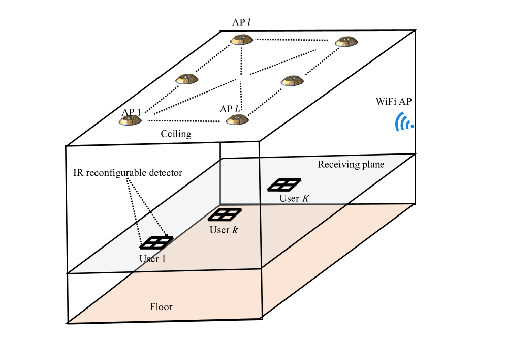
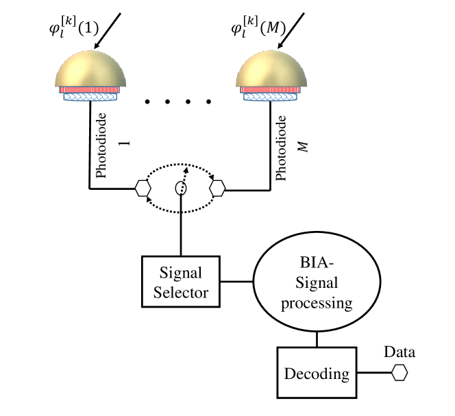
We consider a number of optical APs deployed on the ceiling given by , , and each optical AP consists of a certain number of VCSELs, , as shown in Fig. 1. This optical wireless system serves , , users randomly distributed on the receiving plane. To provide a wide field of view (FoV), each user is equipped with a reconfigurable detector composed of photodiodes, which point to different directions providing linear independent channel responses, as shown in Fig. 2. Focusing on a generic user , , connected to optical AP at time , the signal received at its photodiode , , is
| (1) |
where , is the mode of photodiode at time slot , is the transmitted signal and is real valued additive white Gaussian noise with zero mean and variance given by the sum of shot noise, thermal noise and the intensity noise of the laser, i.e.,
| (2) |
where is the sum of shot noise and thermal noise, and is the relative intensity noise of the VCSEL transmitter [Adnan-Qidan et al., 2021]. Note that, is the interference channel between user and adjacent optical AP , is the responsivity of photodiode , is the optical power of AP and is the single-sided bandwidth of the system.
In this work, a WiFi AP is considered to provide uplink transmission and serve users that receive low optical power from the optical APs. In this context, the optical and WiFi systems are connected to a central unit that controls user association and the resources of the network such that load balancing between the systems is achieved [Adnan-Qidan et al., 2020]. Moreover, the central unit has information on the distribution of the users, in addition to some information that varies based on the transmission scheme considered for managing the interference among the users in the hybrid network. In particular, orthogonal transmission is considered for the WiFi system, while ZF or BIA is applied for the optical system.
2.1 Optical transmitter
The optical channel is usually given by Line-of-Sight (LoS) and diffuse components. That is, the optical channel between AP and user at photodiode is
| (3) |
where corresponds to the LoS link, are non-LoS components and is the delay between them. Note that, a reconfigurable detector is considered in this work, and therefore, each user has a wide FoV receiver, which results in detecting a large portion of the optical power radiated from LoS links. Given this point, non-LoS components can be neglected for the sake of simplicity [Adnan-Qidan et al., 2021].
The power distribution of the VCSEL-based optical AP follows a Gaussian function of multiple modes. In this context, the transmitted power of the optical AP is determined by the beam waist , the wavelength and the distance from the ceiling to the receiving plane. Thus, the beam radius of the laser at distance is
| (4) |
where is the Rayleigh range given by
| (5) |
where is the refractive index of air. Moreover, the intensity spatial distribution of the laser over the transverse plane at distance can be expressed as
| (6) |
where is the radial distance from the center of the beam spot and the distance .
Considering that the detection area of the reconfigurable detector is , all the photodiodes of the reconfigurable detector have the same size and detection area. Thus, the detection area of photodiode is given by , . In this case, the received power of user at photodiode from optical AP is given by
| (7) |
2.2 Reconfigurable detector
The receiver considered in this work is composed of photodiodes that provide channel responses linearly independent following an angle diversity arrangement [Morales-Céspedes et al., 2017]. As shown in Fig. 2, all the photodiodes are connected to a single signal processing chain through a selector, minimizing the power consumption of the receiver. Each photodiode has a unique orientation given by its polar and azimuth angles, which are denoted as and , respectively. Thus, the orientation vector of photodiode of user is given by
| (8) |
Moreover, the irradiance and incidence angles are determined by
| (9) |
| (10) |
respectively, where is the normal orientation vector of optical AP and is the vector from optical AP to user . Note that, each optical AP points to the floor, and hence, the normal orientation vector is . It is worth mentioning that the photodiodes arrangement of a reconfigurable detector can follow different geometrical patterns including pyramidal, hemispherical or random receiving orientation angle (ROA) distributions such that providing distinct and linearly independent channel responses is guaranteed.
At this point, the channel matrix of user connected for example to optical APs is given by
| (11) |
where is the channel response between optical AP and user at the photodiode of the reconfigurable detector. Note that, the reconfigurable detector must consist of at least photodiodes in order to ensure that is a full-rank matrix.
2.3 Uplink transmission
A WiFi system is considered in the hybrid network to provide uplink transmission. In this context, each user has an RF interface to communicate with the WiFi system, and the power allocated to that RF interface is denoted by . The WiFi system devotes resources for the uplink transmission, allocating resources for each user. Note that, the power consumption at the RF interface of each user must be taken into account due to battery limitations. Hence, denoting as power amplifier efficiency, the power consumption equals to . It is worth pointing out that ensuring power consumption within the limit requires the definition of three constraints for the maximum power allocated to the RF interface of the user, the battery power constraint of the user and the minimum rate of the uplink transmission.
3 MULTIPLE ACCESS SCHEMES
In general, optical wireless systems are composed of a high number of optical transmitters that serve multiple users. In such high density wireless networks, multi-user interference is a crucial issue that must be managed efficiently to achieve a high spectral efficiency. In this context, low complexity orthogonal transmission schemes such as TDMA [Abdelhady et al., 2019] and OFDMA [Bawazir et al., 2018] are implemented for this purpose where exclusive time or frequency slots are allocated to each user. In addition, WDMA can be implemented for avoiding multi-user interference by allocating a certain wavelength to each user while using optical filters on the user side to eliminate the other wavelengths. Despite the low complexity of the orthogonal transmission schemes, the utilization of the network resources might be minimized. In the following, advanced transmission schemes are introduced to serve multiple users simultaneously. Note that, the equations below are derived for a simple full connectivity optical wireless system where APs serve users. However, they can be simply extended for our system model in Section 2.
3.0.1 Precoding transmission schemes
TPC schemes, such as ZF in [Marshoud et al., 2015], are proposed for interference management in optical wireless networks assuming prefect CSI at transmitters as well as cooperation among optical APs.
Let us consider linear transmit precoding to manage muti-user interference, and then, derive the achievable user rate. Focussing on user , its precoding vector is denoted as , and its received signal is given by
| (12) |
where the first term is the useful information intended to user and the second term is the interference received due to transmission to the other users, . Moreover, is the symbol transmitted to user . Note that, On–off keying (OOK) can be used in optical wireless communication for the sake of avoiding complexity. The interference term in equation (12) can be canceled using the precoding of the ZF scheme. Furthermore, the channel matrix for the scenario considered in this section, users connected to AP, is given by
| (13) |
where , and the precoding matrix is given by
| (14) |
where . Thus, , where is the channel gain of user after the ZF precoding. In [Marshoud et al., 2015], the lower band user capacity is derived taking into consideration the implementation of the ZF scheme. It is expressed as
| (15) |
Therefore, the achievable user rate of ZF, , can be written as follows
| (16) |
and the sum rate is given by . It is worth mentioning that the pseudo-inverse is , which obeys the ZF criterion to obtain interference-free signals at users.
In addition to the requirement of TPC schemes in terms of the need for CSI at transmitters, the use of TPC schemes in optical wireless networks is subject to limitations due to the optical signal characteristics such as the non-negativity of the transmitted signal and the high correlation among the channel responses of users [Morales-Céspedes et al., 2017, Adnan-Qidan et al., 2019, Qidan et al., 2021b]. It is shown that these schemes achieve low data rates compared to their performance in RF networks. Therefore, the following points must be taken into consideration prior to considering TPC schemes for interference management.
-
•
The need for prefect CSI at optical transmitters.
-
•
Cooperation among optical APs is required.
-
•
The precoding matrix for determining the transmitted signal contains negative and positive values, and therefore, a DC bias current must be applied to guarantee the non negativity of the transmitted signal.
-
•
The performance of TPC schemes is subject to correlation among the channel responses of users.
3.0.2 Blind interference alignment
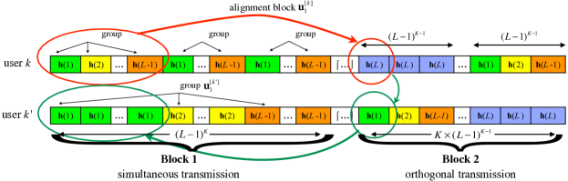
Following [Gou et al., 2011], in this section, the methodology of BIA is introduced in detail in a multiple-input multiple-output broadcast channel (MISO BC) scenario where APs serve users. The key idea of BIA is aligning the useful information intended to each user into a full rank matrix, while having the interfering signals contained into a matrix that has at least one dimension less. Basically, BIA allocates a number of alignment blocks determined in accordance with the size of the network, i.e., the number of transmitters and users, to each user simultaneously. During an alignment block of user , , the channel state of that user changes among distinct preset modes, while the channel states of all other users remain constant, as shown in Fig. 3. Note that, the reconfigurable photodetector derived in Section 2 gives the user the ability to vary its channel state among the symbol extensions, i.e., the time slots, of its alignment block. Denoting a symbol transmitted to user as , where th is the index of an alignment block allocated to user , BIA guarantees the linear independence of the symbols received from transmitters over alignment block . Additionally, the independence among multiple alignment blocks allocated to each user must be ensured during the entire transmission block. To satisfy this condition, the alignment blocks of each user must be transmitted in orthogonal fashion such that any pair of alignment blocks allocated to the same user do not contain any symbol in common, giving each user the ability to decode the information transmitted over its alignment blocks.
Once the independence among the desired symbols of user is ensured, the interference received due to transmission to all other users, for example transmitted to user , , can be aligned into a matrix that has less dimensions than the data streams intended to user during each of its alignment blocks. Given this point, the interference can be measured and subtracted, and DoF carried by can be decoded by user .
To guarantee the methodology mentioned above, the transmission block of BIA is divided into Block 1 and Block 2, comprising time slots in total. As a result, alignment blocks are allocated to each user. Referring to Fig. 3, the contractions of Block 1 and Block 2, as well as the length of each block, are described as follows. In Block 1, transmissions to all users occur simultaneously, causing severe interference among them. On the other hand, each user is served in orthogonal fashion over Block 2 in order to give users enough dimensions to measure and cancel the interference received during Block 1, i.e., user measures the symbols transmitted to all other users , , during Block 2, and subtracts it afterwards from the signal received at Block 1. Therefore, the first slots of each alignment block must belong to Block 1 forming a group, while the last time slot of each alignment block is provided over Block 2. As a result, the length of Block 1 is given by time slots, while Block 2 comprises time slots.
At this point, the signal received by user from transmitters during an alignment block after interference subtraction can be written as
| (17) |
where is the signal received during the time slots of alignment block . Moreover, in (17),
| (18) |
is the channel matrix of user that contains linearly independent channel responses, i.e., is a full rank matrix, and is real valued additive white Gaussian noise with zero mean and variance given by the sum of thermal noise, shot noise and noise that results from interference subtraction, which is defined as a covariance matrix as follows
| (19) |
It is worth mentioning that the performance of BIA is limited in a high density network due to increase in subtraction noise as the number of users increases. Moreover, the requirements of large channel coherence time become more difficult to guarantee in such high density networks. In BIA, the achievable user rate can be written as
| (20) |
where is the ratio of the number of alignment blocks allocated to user to the length of the BIA transmission block, is the power allocated to the data stream and is the covariance matrix of noise.
| Optical system parameters | Value |
|---|---|
| Bandwidth of VCSEL laser | 5 GHz |
| Wavelength of VCSEL laser | 830 nm |
| VCSEL beam waist | m |
| Physical area of the photodiode | 15 |
| Receiver FOV | 45 deg |
| Detector responsivity | 0.53 A/W |
| Gain of optical filter | 1.0 |
| Laser noise | z |
| WiFi parameters | Value |
| OFDM subcarrier number | 108 |
| Transmitted power for Wi-Fi AP | 20 dBm |
| Bandwidth for WiFi AP | 40 MHz |
| Noise power of WiFi | -63 dBm |
4 OPTIMIZATION PROBLEM
The resources of the optical wireless system must be managed among users taking into consideration the existence of the complementary WiFi system to maximize the sum rate of the hybrid optical/RF network. Specifically, an optimization problem is formulated in this section with an objective function that jointly finds the optimal user assignment and resource allocation for multiple users. In previous works on heterogeneous networks, SNR maximization is considered for user assignment to avoid complexity where users simply connect to a wireless system that provides high SNR. However, this approach is not efficient when optical and RF systems work together due to the fact that an optical AP illuminates a small area compared to an RF AP, and therefore, considering SNR maximization might lead to overloading one of these systems [Adnan-Qidan et al., 2020]. Consequently, resource management in such hybrid optical/RF networks must be based on rate maximization where users connect to the system that has more available resources than the other.
Let us define a new notation , that contains all the available APs, i.e., optical and WiFi APs, in the indoor environment, as shown in Fig 1. Moreover, an expression for the achievable user-rate regardless of the optical and WiFi systems can be written as
| (21) |
where is the achievable user rate of a generic user connected to optical or WiFi APs, and denotes the fraction of the resources allocated to user from AP . Note that, the achievable user rate for the optical system is given by equations (20) or (16) based on the transmission scheme considered, BIA or ZF, respectively. On the other hand, the achievable user rate of the WiFi system can be easily derived considering orthogonal frequency-division multiplexing (OFDM) with multiple subcarriers, which are allocated in orthogonal fashion to the users connected to the WiFi system avoiding multi-user interference as in [Adnan-Qidan et al., 2020].
The overall achievable rate of a generic user is given by
| (22) |
where is a variable that determines user association. In this context, the variable if user is connected to AP , otherwise the variable .
At this point, our aim is to formulate an optimization problem that maximizes the sum rate of all the users by assigning each user to an AP that provides a high user-rate. In this context, we define a utility function of the overall user rate in equation (22) under several constraints that ensure the maximization of the hybrid network overall sum rate. That is
| (23) | ||||
| s.t. | ||||
where is a strictly concave function that achieves some levels of fairness among the users of the network if it is considered in its logarithmic form, i.e., [Adnan-Qidan et al., 2020, Qidan et al., 2021a]. The first constraint in (23) ensures that each user connects to only one AP, i.e., one of the optical APs or the WiFi system. The second constraint guarantees that the portion of the transmission resources employed for each optical AP or the WiFi system is less than 1. Moreover, the last constraint considers the feasible region of the optimization variables, where and are binary and real variables between 0 and 1, respectively.
The problem in (23) is MINLP in which two variables, and , are coupled, and therefore, it is not easy to solve. In this sense, a decentralized algorithm via Lagrangian multipliers can be used to provide an effective solution with low computational time. In particular, the Lagrangian function of the main problem in (23) is formulated as
| (24) |
considering is the load on AP and uniform resource allocation among users, i.e., . Note that, is a Lagrangian multiplier that works as a message between AP and users sending requests to connect to that AP. The problem in (24) can be divided into sub-problems, and that can be solved on the user side and the AP side, respectively, more details are in [Adnan-Qidan et al., 2020]
5 PERFORMANCE EVALUATION
An indoor environment is considered with dimensions 5m 5m 3m. On the ceiling, optical APs are deployed to serve users distributed on the receiving plane. Moreover, a WiFi AP is considered to provide uplink transmission as well as serving users who penalize the sum rate of the optical wireless system. In this work, each user is equipped with a reconfigurable detector that contains multiple photodiodes in order to provide linearly independent channel responses from the whole set of the transmitters. In addition, each user has an RF antenna given the fact that some users might be served by the WiFi AP in accordance to the solution of the optimization problem in (23). The rest of the simulation parameters are listed in Table I.
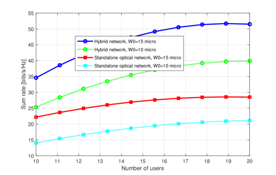
In Fig.4, the sum rate of the hybrid network is shown versus the number of users considering different values of the laser beam waist. Recall that the optimization problem formulated in this work can be solved directly considering equation (24), i.e., a decentralized algorithm, due to its practicality where a sub-optimal solution close to the solution of the centralized algorithm can be obtained with low complexity. The figure shows that the sum rate increases with the number of users where each user experiences a different channel gain. Note that, the hybrid network achieves higher sum rate compared with the standalone optical wireless network, in which the WiFi AP provides only uplink transmission, and it is not considered in the optimization problem that maximizes the sum rate of the users in downlink transmission. Furthermore, the sum rates of all the scenarios increase with increase in the beam waist of the laser due to the fact that the received power of each user increases considerably with the beam waist as more power is focused towards the users.
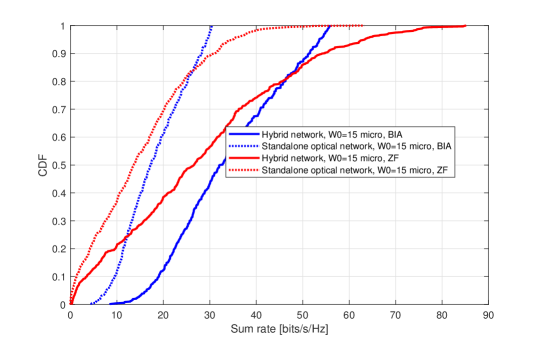
Finally, Fig. 5 shows the cumulative distribution function (CDF) of the sum rate in the hybrid network implementing BIA or ZF schemes to align multi-user interference. It is shown that BIA is superior to ZF and more suitable for the optical wireless system due to the fact that BIA naturally satisfies the non-negativity of the optical signal, and therefore, it helps in avoiding the need for applying a DC bias current to the optical signal, which might cause clipping distortion to useful information. It is worth mentioning that BIA suffers data rate degradation as the number of users increases in the network due to channel coherence requirements and noise enhancement. However, in the case of the hybrid network, some of the users negatively impacting the sum rate within the coverage of each optical AP can be moved to the WiFi system such that the overall sum rate of the hybrid network is maximized.
6 CONCLUSIONS
In this paper, the performance of an optical wireless system using IR lasers is evaluated taking into consideration the existence of a WiFi system. First, the system model composed of multiple IR lasers on the ceiling serving multiple users is defined. In addition, a WiFi system is considered to provide uplink transmission and serve users that overload the optical wireless system. Then, two transmission schemes are defined for the optical wireless system, ZF and BIA, to derive the achievable user rates. After that, an optimization problem is formulated to jointly find the optimal user association and resource allocation that maximize the overall sum rate of the hybrid network. The optimization problem is a MINLP complex problem, which is difficult to solve. Therefore, a decentralized algorithm is proposed via Lagrangian multipliers where the main problem is divided into sub-problems that can be solved separately. The results show significant enhancement in the sum rate of the hybrid optical/RF network after performing the optimization problem that considers all the APs in the environment including the WiFi system.
7 FUTURE DIRECTIONS
IR laser-based optical wireless communication can unlock data rate speeds in a range of Tbps. However, crucial wireless communication issues ranging from the physical layer, the data link layer and the network layer must be addressed including transmitter and receiver designs, developing highly efficient interference management schemes and optimal resource allocation approaches and backhaul network designs, etc. In general, these issues might lead to formulating complex optimization problems that are difficult to solve. Note that, some optimization tools are available to solve such complex optimization problems. However, practical algorithms are highly required especially when real-time scenarios are concerned.
In recent years, machine learning (ML) techniques have been studied for solving NP-hard optimization problems with different contexts [Sun et al., 2019, Zhu et al., 2020]. For instance, some of the previous works in the literature related to the optimization problem formulated in this paper [Elgamal et al., 2021, Shrivastava et al., 2020, Ahmad et al., 2020] consider the implementation of reinforcement learning (RL) to solve various optimization problems in optical and RF systems where RL can interact with an environment to learn an optimal policy that makes right decisions. Specifically, in [Elgamal et al., 2021], reinforcement learning is used for assigning each user to an exclusive wavelength in a WDMA-based optical wireless network. In [Shrivastava et al., 2020], a deep Q-network (DQN) learning-based algorithm is proposed for solving an optimization problem that aims to maximize the sum rate of a hybrid optical/RF network through allocating power and bandwidth in addition to user association. In [Ahmad et al., 2020], a RL-based load balancing approach is proposed for maximizing the sum rate of users in a hybrid LiFi/ WiFi network. It is shown that ML techniques can provide sub-optimal solutions while avoiding complexity. However, conventional ML techniques are not suitable in terms of providing immediate solutions in large size optical wireless networks. As future work, deep learning can be used for solving various optimization problems as it is expected to be superior to ML techniques where a learning process is preformed over a data set generated in an offline phase to provide sub-optimal solutions in a real time phase.
ACKNOWLEDGEMENTS
This work has been supported in by the Engineering and Physical Sciences Research Council (EPSRC), in part by the INTERNET project under Grant EP/H040536/1, and in part by the STAR project under Grant EP/K016873/1 and in part by the TOWS project under Grant EP/S016570/1. All data are provided in full in the results section of this paper.
REFERENCES
- Abdelhady et al., 2019 Abdelhady, A. M., Amin, O., Chaaban, A., Shihada, B., and Alouini, M.-S. (2019). Downlink resource allocation for dynamic tdma-based vlc systems. IEEE Transactions on Wireless Communications, 18(1):108–120.
- Adnan-Qidan et al., 2021 Adnan-Qidan, A., Morales-Cespedes, M., Garcia-Armada, A., and Elmirghani, J. M. H. (2021). Resoures allocation in laser-based optical wireless networks. In GLOBECOM 2021 - IEEE Global Communications Conference, pages 1–6.
- Adnan-Qidan et al., 2020 Adnan-Qidan, A., Morales-Céspedes, M., and Armada, A. G. (2020). Load balancing in hybrid vlc and rf networks based on blind interference alignment. IEEE Access, 8:72512–72527.
- Adnan-Qidan et al., 2019 Adnan-Qidan, A., Morales Céspedes, M., and García Armada, A. (2019). User-centric blind interference alignment design for visible light communications. IEEE Access, 7:21220–21234.
- Ahmad et al., 2020 Ahmad, R., Soltani, M. D., Safari, M., Srivastava, A., and Das, A. (2020). Reinforcement learning based load balancing for hybrid lifi wifi networks. IEEE Access, 8:132273–132284.
- Alazwary et al., 2021 Alazwary, K., Qidan, A. A., El-Gorashi, T., and Elmirghani, J. M. H. (2021). Rate splitting in vcsel-based optical wireless networks. In 2021 6th International Conference on Smart and Sustainable Technologies (SpliTech), pages 1–5.
- Bawazir et al., 2018 Bawazir, S. S., Sofotasios, P. C., Muhaidat, S., Al-Hammadi, Y., and Karagiannidis, G. K. (2018). Multiple access for visible light communications: Research challenges and future trends. IEEE Access, 6:26167–26174.
- Elgamal et al., 2021 Elgamal, A. S., Alsulami, O. Z., Qidan, A. A., El-Gorashi, T. E., and Elmirghani, J. M. H. (2021). Q-learning algorithm for resource allocation in wdma-based optical wireless communication networks. In 2021 6th International Conference on Smart and Sustainable Technologies (SpliTech), pages 1–5.
- Gou et al., 2011 Gou, T., Wang, C., and Jafar, S. A. (2011). Aiming perfectly in the dark-blind interference alignment through staggered antenna switching. IEEE Transactions on Signal Processing, 59(6):2734–2744.
- Li et al., 2014 Li, H., Chen, X., Guo, J., and Chen, H. (2014). A 550 mbit/s real-time visible light communication system based on phosphorescent white light led for practical high-speed low-complexity application. Opt. Express, 22(22):27203–27213.
- Marshoud et al., 2015 Marshoud, H., Dawoud, D., Kapinas, V. M., Karagiannidis, G. K., Muhaidat, S., and Sharif, B. (2015). Mu-mimo precoding for vlc with imperfect csi. In 2015 4th International Workshop on Optical Wireless Communications (IWOW), pages 93–97.
- Morales-Céspedes et al., 2017 Morales-Céspedes, M., Paredes, M. P., Armada, A. G., and Vandendorpe, L. (2017). Aligning the light without channel state information for visible light communications. to appear in IEEE Journal on Selected Areas in Communications.
- Pham et al., 2017 Pham, T. V., Le-Minh, H., and Pham, A. T. (2017). Multi-user visible light communication broadcast channels with zero-forcing precoding. IEEE Transactions on Communications, 65(6):2509–2521.
- Qidan et al., 2018 Qidan, A. A., Morales-Cespedes, M., and Armada, A. G. (2018). The role of wifi in lifi hybrid networks based on blind interference alignment. In 2018 IEEE 87th Vehicular Technology Conference (VTC Spring), pages 1–5.
- Qidan et al., 2021a Qidan, A. A., Morales Cespedes, M., Garcia Armada, A., and Elmirghani, J. M. (2021a). Resource allocation in user-centric optical wireless cellular networks based on blind interference alignment. Journal of Lightwave Technology, pages 1–1.
- Qidan et al., 2021b Qidan, A. A., Morales-Céspedes, M., Armada, A. G., and Elmirghani, J. M. H. (2021b). User-centric cell formation for blind interference alignment in optical wireless networks. In ICC 2021 - IEEE International Conference on Communications, pages 1–7.
- Qiu et al., 2018 Qiu, Y., Chen, S., Chen, H.-H., and Meng, W. (2018). Visible light communications based on cdma technology. IEEE Wireless Communications, 25(2):178–185.
- Shrivastava et al., 2020 Shrivastava, S., Chen, B., Chen, C., Wang, H., and Dai, M. (2020). Deep q-network learning based downlink resource allocation for hybrid rf/vlc systems. IEEE Access, 8:149412–149434.
- Sifaou et al., 2017 Sifaou, H., Kammoun, A., Park, K.-H., and Alouini, M.-S. (2017). Robust transceivers design for multi-stream multi-user mimo visible light communication. IEEE Access, 5:26387–26399.
- Sun et al., 2019 Sun, Y., Peng, M., Zhou, Y., Huang, Y., and Mao, S. (2019). Application of machine learning in wireless networks: Key techniques and open issues. IEEE Communications Surveys Tutorials, 21(4):3072–3108.
- Wang et al., 2014 Wang, C.-X., Haider, F., Gao, X., You, X.-H., Yang, Y., Yuan, D., Aggoune, H. M., Haas, H., Fletcher, S., and Hepsaydir, E. (2014). Cellular architecture and key technologies for 5g wireless communication networks. IEEE Communications Magazine, 52(2):122–130.
- Wang et al., 2017 Wang, Y., Basnayaka, D. A., Wu, X., and Haas, H. (2017). Optimization of load balancing in hybrid lifi/rf networks. IEEE Transactions on Communications, 65(4):1708–1720.
- Zhu et al., 2020 Zhu, G., Liu, D., Du, Y., You, C., Zhang, J., and Huang, K. (2020). Toward an intelligent edge: Wireless communication meets machine learning. IEEE Communications Magazine, 58(1):19–25.