Mixed Dual-Hop IRS-Assisted FSO-RF Communication System with H-ARQ Protocols

Gyan Deep Verma, Aashish Mathur, Yun Ai, and Michael Cheffena
Abstract

Intelligent reflecting surface (IRS) is an emerging key technology for the fifth-generation (5G) and beyond wireless communication systems to provide more robust and reliable communication links. In this paper, we propose a mixed dual-hop free-space optical (FSO)-radio frequency (RF) communication system that serves the end user via a decode-and-forward (DF) relay employing hybrid automatic repeat request (H-ARQ) protocols on both hops. Novel closed-form expressions of the probability density function (PDF) and cumulative density function (CDF) of the equivalent end-to-end signal-to-noise ratio (SNR) are computed for the considered system. Utilizing the obtained statistics functions, we derive the outage probability (OP) and packet error rate (PER) of the proposed system by considering generalized detection techniques on the source-to-relay (S-R) link with H-ARQ protocol and IRS having phase error. We obtain useful insights into the system performance through the asymptotic analysis which aids to compute the diversity gain. The derived analytical results are validated using Monte Carlo simulation.

Index Terms:
Free-space optical (FSO) communication, decode-and-forward (DF) relaying, Gamma-Gamma (GG) turbulence, pointing errors (PEs), intelligent reflecting surface (IRS), hybrid automatic repeat request (H-ARQ), intensity modulation/direct detection (IM/DD), heterodyne detection (HD).

I Introduction

IN recent decade, free-space optical (FSO) communication systems have received significant attention in academic and industrial research. FSO systems feature a license-free band, higher bandwidth, no electromagnetic interference (EMI), and a more secure communication link compared to traditional radio frequency (RF) communication systems due to the inherent properties of optical laser beams [1]. However, the atmospheric turbulence (AT) and pointing errors (PEs) may lead to severe degradation in intensity, phase, and polarization of the received signal, especially for the long distance communications [1, 2, 3].

Various methods have been developed by researchers to overcome the effects of AT and PEs effectively, one of which is to use co-operative communication [4]. A mixed dual-hop FSO-RF wireless communication system has been a promising approach for leveraging both wireless techniques to increase capacity, reduce power consumption, and extend wireless coverage by compensating the deteriorating effects of AT and PEs. The decode-and-forward (DF) relay is an intermediate relay node that is used to connect both hops. The DF relay node’s objective is to decode the incoming signal and re-transmit it to the next hop. To further improve the performance of the communication systems, hybrid automatic repeat request (H-ARQ) techniques can be utilized, which combines forward error correction (FEC) with re-transmission request protocols [5], [6]. The approximate packet error rate (PER) of an RF communication system using H-ARQ with chase combining (CC) protocol was obtained in [7], [8]. The authors in [9], computed the outage probability (OP) and throughput performance of FSO communication systems employing various H-ARQ protocols under the combined influence of Gamma-Gamma (GG) distributed AT and PEs.

The use of intelligent reflecting surface (IRS) has been proposed very recently in literature to improve the RF system performance. The IRS is made up of a large number of reflecting active antenna plates with a micro-controller, which enables to control amplitude, frequency, phase, and polarization of the incident electromagnetic signals. Moreover, it does not require much signal processing, such as encoding, decoding, and amplification [10]. The IRS or meta-surfaces have been extensively explored in the literature, for their merits such as, capability of the greater coverage, improved spectrum and energy efficiency [4], [11, 12, 13]. In [4], the authors reported OP and BER performance for an IRS-aided dual-hop FSO-RF communication system. An IRS-assisted dual-hop mixed FSO-RF communication system was recently proposed in [11] where the OP and BER performance under the influence of co-channel interference (CCI) were evaluated. The authors in [12] performed OP analysis for an RF communication system using the H-ARQ with CC protocol over an IRS assisted with perfect phases estimation. However, the effect of phase errors in IRS was not considered in the aforementioned works.

Motivated by the recent studies on mixed FSO-RF communication systems using IRS and the benefits of H-ARQ protocols to improve the reliability of communication systems, we study the performance of an IRS-assisted mixed dual-hop FSO-RF communication system with H-ARQ protocols in this work. To the best of the authors’ knowledge, such a cascaded system employing H-ARQ protocols over both links has not been investigated in literature. The following are the key contributions of our research work:

  1. 1.

    We derive closed-form expression of the probability density function (PDF) and cumulative distribution function (CDF) of the accumulated signal-to-noise ratio (SNR) with imperfect IRS phase and H-ARQ protocol. Furthermore, using these expressions, we calculate the theoretic information OP and PER for the considered system.

  2. 2.

    We analyze the impact of various system parameters such as the number of IRS reflecting plates, number of transmission rounds, von Mises distribution concentration parameter (phase estimation accuracy of IRS), and packet length on the OP and PER performance which provide significant design insights into the considered system.

  3. 3.

    Useful insights into the system performance are obtained through the asymptotic expression of the OP.

II System Description

We consider a cascaded dual-hop FSO-RF communication system where H-ARQ technique is employed on both the links. We assume that a source node (S𝑆S) communicates with a destination node (D𝐷D) via intermediary DF based relay (R𝑅R). Due to obstructions caused by high-rise buildings and other impediments, it is justified that there is no direct path between source-to-destination (S𝑆S-D𝐷D) and relay-to-destination (R𝑅R-D𝐷D) [4]. Hence, IRS is utilized on the RF link (R𝑅R-D𝐷D).

Refer to caption
Figure 1: Mixed dual-hop FSO-RF communication system model with IRS and H-ARQ protocol.

The S𝑆S-R𝑅R link is a FSO link which is subjected to GG AT and PEs. For the FSO signal reception, both the heterodyne detection (HD) and intensity modulation and direct detection (IM/DD) techniques can be used. Rician and Rayleigh distributions are used on the RF hop between R𝑅R-IRS and IRS-D𝐷D, respectively, while von Mises distribution describes the phase shift errors of the IRS [14].

II-A FSO Transmission Link

On the FSO communication link, we assume a single transmitter (Tx) and receiver (Rx) and use H-ARQ with CC protocol to enhance the system performance. The baseband electrical signal is represented after optical-to-electrical (O-E) conversion as follows:

ySR=ηes1h+wR,subscript𝑦𝑆𝑅subscript𝜂𝑒subscript𝑠1subscript𝑤𝑅y_{SR}=\eta_{e}s_{1}h+w_{R},\vspace{-0.5em} (1)

where ηesubscript𝜂𝑒\eta_{e} is the effective O-E conversion coefficient and the transmitted optical signal is s1subscript𝑠1s_{1}. The FSO channel gain is represented as hh=hlhahpsubscript𝑙subscript𝑎subscript𝑝h_{l}h_{a}h_{p}, where hlsubscript𝑙h_{l} denotes path loss which arises due to dust, rain, fog, snow, and other atmospheric impairments [15], hasubscript𝑎h_{a} signifies AT, which is caused by inhomogeneities present along the optical beam path, and hpsubscript𝑝h_{p} indicates PE, which is caused by thermal expansion, earthquakes, and other factors [2]. It is assumed that the transmitted power is 𝔼[s1]𝔼delimited-[]subscript𝑠1\mathbb{E}\left[s_{1}\right]=P1subscript𝑃1P_{1}, where 𝔼[.]\mathbb{E}\left[.\right] is the expectation operator, wRC𝒩(0,σR2)similar-tosubscript𝑤𝑅𝐶𝒩0subscriptsuperscript𝜎2𝑅w_{R}\sim C\mathcal{N}(0,\sigma^{2}_{R}) denotes the complex additive white Gaussian noise (AWGN) with zero mean and variance σR2subscriptsuperscript𝜎2𝑅\sigma^{2}_{R} at the relay node [3]. The composite PDF of the received irradiance at the relay in the qthsuperscript𝑞𝑡q^{th} round is expressed as [16, Eq. (8)],

fhSRq(hq)=abξ2A0hqΓ(a)Γ(b)G1,33,0(abhqA0|ξ2+1ξ2,a,b).subscript𝑓subscript𝑆subscript𝑅𝑞subscript𝑞𝑎𝑏superscript𝜉2subscript𝐴0subscript𝑞Γ𝑎Γ𝑏superscriptsubscript𝐺1330conditional𝑎𝑏subscript𝑞subscript𝐴0FRACOPsuperscript𝜉21superscript𝜉2𝑎𝑏\displaystyle f_{h_{SR_{q}}}(h_{q})=\frac{ab\xi^{2}}{{A}_{0}h_{q}\Gamma(a)\Gamma(b)}G_{1,3}^{3,0}\Big{(}\frac{abh_{q}}{A_{0}}\Big{|}{{\xi^{2}+1}\atop{\xi^{2},a,b}}\Big{)}. (2)

In (2), Gu,vs,t(z|c1,,cud1,,dv)subscriptsuperscript𝐺𝑠𝑡𝑢𝑣conditional𝑧subscript𝑐1subscript𝑐𝑢subscript𝑑1subscript𝑑𝑣G^{s,t}_{u,v}\left(z\left|{\begin{array}[]{c}c_{1},\dots,c_{u}\\ d_{1},\dots,d_{v}\end{array}}\right.\right) represents the Meijer G-function [17, Eq. (9.301)] and Γ(.)\Gamma(.) denotes the Gamma function [17, Eq. (8.31)]. The system parameters a𝑎a, b𝑏b, and ξ2superscript𝜉2\xi^{2} are discussed in depth in [16]. After N1subscript𝑁1N_{1} independent and identical H-ARQ transmission rounds over the S𝑆S-R𝑅R link, the random variable (RV) for the accumulated SNR is ZSRsubscript𝑍𝑆𝑅Z_{SR}=q=1N1γSRqsuperscriptsubscript𝑞1subscript𝑁1subscript𝛾𝑆subscript𝑅𝑞\sum_{q=1}^{N_{1}}\gamma_{SR_{q}}, where γSRqsubscript𝛾𝑆subscript𝑅𝑞\gamma_{SR_{q}}=(ηehq)r/σR2superscriptsubscript𝜂𝑒subscript𝑞𝑟subscriptsuperscript𝜎2𝑅(\eta_{e}h_{q})^{r}/\sigma^{2}_{R} represents the instantaneous SNR on the S𝑆S-R𝑅R link in the qthsuperscript𝑞𝑡q^{th} round and r𝑟r={1,2}12\left\{1,2\right\} denotes HD and IM/DD, respectively. Further, using [16, Eq. (26)], the PDF of the RV ZSRsubscript𝑍𝑆𝑅Z_{SR} is written as

fZSR(z)=l1+l2+l3=N10l1,l2,l3N1(N1l1,l2,l3)n=0Dn(l1,l2,l3)zEr1Γ(Er)γ¯SRrEr.subscript𝑓subscript𝑍𝑆𝑅𝑧subscriptFRACOPsubscript𝑙1subscript𝑙2subscript𝑙3subscript𝑁1formulae-sequence0subscript𝑙1subscript𝑙2subscript𝑙3subscript𝑁1FRACOPsubscript𝑁1subscript𝑙1subscript𝑙2subscript𝑙3subscriptsuperscript𝑛0subscript𝐷𝑛subscript𝑙1subscript𝑙2subscript𝑙3superscript𝑧𝐸𝑟1Γ𝐸𝑟superscriptsubscript¯𝛾𝑆subscript𝑅𝑟𝐸𝑟f_{Z_{SR}}(z)=\sum_{{l_{1}+l_{2}+l_{3}}=N_{1}\atop{0\leq l_{1},l_{2},l_{3}\leq N_{1}}}\left({N_{1}}\atop{l_{1},l_{2},l_{3}}\right)\sum^{\infty}_{n=0}\frac{D_{n}(l_{1},l_{2},l_{3})z^{\frac{E}{r}-1}}{\Gamma\left(\frac{E}{r}\right)\bar{\gamma}_{SR_{r}}^{\frac{E}{r}}}.\vspace{-0.7em} (3)

In (3), the parameters Dn(l1,l2,l3)subscript𝐷𝑛subscript𝑙1subscript𝑙2subscript𝑙3D_{n}(l_{1},l_{2},l_{3})=X0~l1(Yn~(l2)Zn~(l3))superscript~subscript𝑋0subscript𝑙1superscript~subscript𝑌𝑛subscript𝑙2superscript~subscript𝑍𝑛subscript𝑙3\tilde{X_{0}}^{l_{1}}(\tilde{Y_{n}}^{(l_{2})}*\tilde{Z_{n}}^{(l_{3})}) are defined in [16, Eq. (13)], γ¯SRrsubscript¯𝛾𝑆subscript𝑅𝑟\bar{\gamma}_{SR_{r}}=(ηeE[hq])r/σR2superscriptsubscript𝜂𝑒𝐸delimited-[]subscript𝑞𝑟subscriptsuperscript𝜎2𝑅(\eta_{e}E[h_{q}])^{r}/\sigma^{2}_{R}, E[hq]𝐸delimited-[]subscript𝑞E\left[h_{q}\right]=(A0ξ2)/(ξ2+1)subscript𝐴0superscript𝜉2superscript𝜉21(A_{0}\xi^{2})/(\xi^{2}+1), E𝐸E=n+l1ξ2+l2a+l3b𝑛subscript𝑙1superscript𝜉2subscript𝑙2𝑎subscript𝑙3𝑏n+l_{1}\xi^{2}+l_{2}a+l_{3}b, * denotes convolution, and Yn~(l2)superscript~subscript𝑌𝑛subscript𝑙2\tilde{Y_{n}}^{(l_{2})} shows that Yn~~subscript𝑌𝑛\tilde{Y_{n}} is convoluted (l21)subscript𝑙21(l_{2}-1) times with itself. Moreover, by integrating (3) with respect to z𝑧z, the CDF of the RV ZSRsubscript𝑍𝑆𝑅Z_{SR} is derived as

FZSR(z)=l1+l2+l3=N10l1,l2,l3N1(N1l1,l2,l3)n=0Dn(l1,l2,l3)zErΓ(Er)(Er)γ¯SRrEr.subscript𝐹subscript𝑍𝑆𝑅𝑧subscriptFRACOPsubscript𝑙1subscript𝑙2subscript𝑙3subscript𝑁1formulae-sequence0subscript𝑙1subscript𝑙2subscript𝑙3subscript𝑁1FRACOPsubscript𝑁1subscript𝑙1subscript𝑙2subscript𝑙3subscriptsuperscript𝑛0subscript𝐷𝑛subscript𝑙1subscript𝑙2subscript𝑙3superscript𝑧𝐸𝑟Γ𝐸𝑟𝐸𝑟superscriptsubscript¯𝛾𝑆subscript𝑅𝑟𝐸𝑟F_{Z_{SR}}(z)=\sum_{{l_{1}+l_{2}+l_{3}}=N_{1}\atop{0\leq l_{1},l_{2},l_{3}\leq N_{1}}}\left({N_{1}}\atop{l_{1},l_{2},l_{3}}\right)\sum^{\infty}_{n=0}\frac{D_{n}(l_{1},l_{2},l_{3})z^{\frac{E}{r}}}{\Gamma\left(\frac{E}{r}\right)\left(\frac{E}{r}\right)\bar{\gamma}_{SR_{r}}^{\frac{E}{r}}}.\vspace{-0.7em} (4)

II-B RF Transmission Link

We assume that the R𝑅R-D𝐷D link is an RF link that utilizes IRS with M𝑀M identical antenna reflector plates that serve as an intermediary node between R and D (spaces between two plates are maintained at least half wavelength). The RF signal after reflection from the IRS and received at D𝐷D is written as follows [14]:

yRD=Mγ0[i=1MI1iI2iI3iejΘi]s2+wD,subscript𝑦𝑅𝐷𝑀subscript𝛾0delimited-[]superscriptsubscript𝑖1𝑀subscript𝐼subscript1𝑖subscript𝐼subscript2𝑖subscript𝐼subscript3𝑖superscript𝑒𝑗subscriptΘ𝑖subscript𝑠2subscript𝑤𝐷y_{RD}=M\sqrt{\gamma_{0}}\left[{\sum_{i=1}^{M}I_{1_{i}}I_{2_{i}}I_{3_{i}}e^{j\Theta_{i}}}\right]s_{2}+w_{D},\vspace{-0.6em} (5)

where s2subscript𝑠2s_{2} is the transmitted symbol from R𝑅R to D𝐷D and 𝔼[s2]𝔼delimited-[]subscript𝑠2\mathbb{E}\left[s_{2}\right]=111, γ0subscript𝛾0\gamma_{0} represents the average SNR when single reflecting plate is present, I1isubscript𝐼subscript1𝑖I_{1_{i}}=(d1)ν/2αiexp(jθi)superscriptsubscript𝑑1𝜈2subscript𝛼𝑖𝑗subscript𝜃𝑖(d_{1})^{-\nu/2}\alpha_{i}\exp(-j\theta_{i}) and I2isubscript𝐼subscript2𝑖I_{2_{i}}=(d2)ν/2βiexp(jψi)superscriptsubscript𝑑2𝜈2subscript𝛽𝑖𝑗subscript𝜓𝑖(d_{2})^{-\nu/2}\beta_{i}\exp(-j\psi_{i}) are the channel gains of the R𝑅R-RIS and RIS-D𝐷D links, and ν𝜈\nu is the path loss exponent. Further, d1subscript𝑑1d_{1}, θisubscript𝜃𝑖\theta_{i}, and αisubscript𝛼𝑖\alpha_{i} are the distance, phase shift, and the Rician fading channel on the R𝑅R-IRS link, respectively [14]. Likewise, d2subscript𝑑2d_{2}, ψisubscript𝜓𝑖\psi_{i}, and βisubscript𝛽𝑖\beta_{i} are the distance, phase shift, and the Rayleigh fading channel on the IRS-R𝑅R link, respectively [14]. I3isubscript𝐼subscript3𝑖I_{3_{i}}=δiexp(jϕi)subscript𝛿𝑖𝑗subscriptitalic-ϕ𝑖\delta_{i}\exp(j\phi_{i}) is the reflection coefficient induced by the ithsuperscript𝑖𝑡i^{th} IRS reflector, δisubscript𝛿𝑖\delta_{i}=111, isubscriptfor-all𝑖\forall_{i} and wDC𝒩(0,σD2)similar-tosubscript𝑤𝐷𝐶𝒩0subscriptsuperscript𝜎2𝐷w_{D}\sim C\mathcal{N}(0,\sigma^{2}_{D}) denotes the complex AWGN with zero mean and σD2subscriptsuperscript𝜎2𝐷\sigma^{2}_{D} variance at node D𝐷D. The authors of [11], [12], [18] assumed that the IRS estimates perfect phase shift ϕisubscriptitalic-ϕ𝑖\phi_{i}=θisubscript𝜃𝑖\theta_{i}+ψisubscript𝜓𝑖\psi_{i} which nullifies the total phase shift that results in maximizing the SNR at D𝐷D. However, in practical scenarios the phase shift induced by the channel is difficult to perfectly estimate [14]. Therefore, in this work, we incorporate the phase deviation defined as θisubscript𝜃𝑖\theta_{i}+ψisubscript𝜓𝑖\psi_{i}-ϕisubscriptitalic-ϕ𝑖\phi_{i}=ΘisubscriptΘ𝑖\Theta_{i} in our analysis, where ΘisubscriptΘ𝑖\Theta_{i} is randomly distributed over [π,π)𝜋𝜋[-\pi,\pi) and is modeled by the circular distribution. The combined PDF of the R𝑅R-IRS and IRS-D𝐷D channels for the jthsuperscript𝑗𝑡j^{th} transmission round after incorporating phase shift errors is comparable to a direct channel with Nakagami distribution and is given by [14, Eq. (11-12)]

f|IRDj|(x)=2mmΓ(m)μ2mx2m1exp(mμ2x2),subscript𝑓subscript𝐼𝑅subscript𝐷𝑗𝑥2superscript𝑚𝑚Γ𝑚superscript𝜇2𝑚superscript𝑥2𝑚1𝑚superscript𝜇2superscript𝑥2f_{|I_{RD_{j}}|}(x)=\frac{2m^{m}}{\Gamma(m)\mu^{2m}}x^{2m-1}\exp\left({-\frac{m}{\mu^{2}}x^{2}}\right),\vspace{-0.55em} (6)

where |IRDj|subscript𝐼𝑅subscript𝐷𝑗|I_{RD_{j}}|=1Mi=1M|I1i||I2i||I3i|exp(jΘi)1𝑀superscriptsubscript𝑖1𝑀subscript𝐼subscript1𝑖subscript𝐼subscript2𝑖subscript𝐼subscript3𝑖𝑗subscriptΘ𝑖\frac{1}{M}\sum_{i=1}^{M}|I_{1_{i}}||I_{2_{i}}||I_{3_{i}}|\exp({j\Theta_{i}}) , μ𝜇\mu is the common mean of M𝑀M complex variables, and m𝑚m is the shaping parameter. The parameter m𝑚m depends on M𝑀M, Iϑ(k)subscript𝐼italic-ϑ𝑘I_{\vartheta}(k), E[I1i]𝐸delimited-[]subscript𝐼subscript1𝑖E[I_{1_{i}}], and E[I2i]𝐸delimited-[]subscript𝐼subscript2𝑖E[I_{2_{i}}], where Iϑ(k)subscript𝐼italic-ϑ𝑘I_{\vartheta}(k) represents modified Bessel function of the first kind of order ϑitalic-ϑ\vartheta, and k𝑘k is concentration parameter of von Mises distribution [14, Eq. (12)]. The instantaneous SNR of the jthsuperscript𝑗𝑡j^{th} transmission round at D𝐷D is γRDjsubscript𝛾𝑅subscript𝐷𝑗\gamma_{RD_{j}}=Mγ0|IRDj2|𝑀subscript𝛾0subscriptsuperscript𝐼2𝑅subscript𝐷𝑗M\gamma_{0}|I^{2}_{RD_{j}}|. Now, using (6), the PDF of the instantaneous SNR on the R𝑅R-D𝐷D link on the jthsuperscript𝑗𝑡j^{th} H-ARQ round is computed as follows:

fγRDj(γRDj)=mmΓ(m)γ¯RDmγRDjm1exp(mγ¯RDγRDj),subscript𝑓subscript𝛾𝑅subscript𝐷𝑗subscript𝛾𝑅subscript𝐷𝑗superscript𝑚𝑚Γ𝑚superscriptsubscript¯𝛾𝑅𝐷𝑚superscriptsubscript𝛾𝑅subscript𝐷𝑗𝑚1𝑚subscript¯𝛾𝑅𝐷subscript𝛾𝑅subscript𝐷𝑗f_{\gamma_{RD_{j}}}(\gamma_{RD_{j}})=\frac{m^{m}}{\Gamma(m)\bar{\gamma}_{RD}^{m}}\gamma_{RD_{j}}^{m-1}\exp\left({-\frac{m}{\bar{\gamma}_{RD}}\gamma_{RD_{j}}}\right),\vspace{-0.6em} (7)

where γ¯RDsubscript¯𝛾𝑅𝐷\bar{\gamma}_{RD}=M2γ0superscript𝑀2subscript𝛾0M^{2}\gamma_{0}. Let ZRDsubscript𝑍𝑅𝐷Z_{RD}=j=1N2γRDjsuperscriptsubscript𝑗1subscript𝑁2subscript𝛾𝑅subscript𝐷𝑗\sum_{j=1}^{N_{2}}\gamma_{RD_{j}} represent the accumulated instantaneous SNR after N2subscript𝑁2N_{2} independent and identical H-ARQ transmission rounds at node D𝐷D. Utilizing (7), the moment generating function (MGF) of the RV ZRDsubscript𝑍𝑅𝐷Z_{RD} is calculated as

ZRD(s)=mN2Γ(m)N2(s+mγ¯RD)mN2.subscriptsubscript𝑍𝑅𝐷𝑠superscript𝑚subscript𝑁2Γsuperscript𝑚subscript𝑁2superscript𝑠𝑚subscript¯𝛾𝑅𝐷𝑚subscript𝑁2{\cal M}_{Z_{RD}}\left(s\right)=\frac{m^{N_{2}}\Gamma(m)^{N_{2}}}{{\left(s+\frac{m}{\bar{\gamma}_{RD}}\right)^{mN_{2}}}}.\vspace{-0.7em} (8)

Taking the inverse Laplace transform of (8) and after some algebra, the PDF of the RV ZRDsubscript𝑍𝑅𝐷Z_{RD} is obtained as

fZRD(t)=(mtγ¯RD)N2emtγ¯RD(N2m1)!.subscript𝑓subscript𝑍𝑅𝐷𝑡superscript𝑚𝑡subscript¯𝛾𝑅𝐷subscript𝑁2superscript𝑒𝑚𝑡subscript¯𝛾𝑅𝐷subscript𝑁2𝑚1\displaystyle f_{Z_{RD}}(t)=\left(\frac{mt}{\bar{\gamma}_{RD}}\right)^{N_{2}}\frac{e^{\frac{mt}{\bar{\gamma}_{RD}}}}{(N_{2}m-1)!}.\vspace{-0.7em} (9)

Integrating (9), the CDF of ZRDsubscript𝑍𝑅𝐷Z_{RD} is derived as

FZRD(t)=γ¯RDmΥ(mtγ¯RD,N2m1)(N2m+1)!,subscript𝐹subscript𝑍𝑅𝐷𝑡subscript¯𝛾𝑅𝐷𝑚Υ𝑚𝑡subscript¯𝛾𝑅𝐷subscript𝑁2𝑚1subscript𝑁2𝑚1\displaystyle F_{Z_{RD}}(t)=\frac{\bar{\gamma}_{RD}}{m}\frac{\Upsilon\left(\frac{mt}{\bar{\gamma}_{RD}},N_{2}m-1\right)}{(N_{2}m+1)!},\vspace{-0.7em} (10)

where Υ(.,.)\Upsilon(.,.) is the lower incomplete Gamma function [17, Eq. (8.350)].

III Performance Analysis

III-A Equivalent end-to-end SNR

The CDF of the equivalent end-to-end SNR for the aforementioned communication system is given by [19, Eq. (7)]

Fγeq(γ)subscript𝐹subscript𝛾𝑒𝑞𝛾\displaystyle F_{\gamma_{eq}}(\gamma) =Pr[min(ZSR,ZRD)<γ]absentPrdelimited-[]subscript𝑍𝑆𝑅subscript𝑍𝑅𝐷𝛾\displaystyle=\text{Pr}[\min(Z_{SR},Z_{RD})<\gamma]
=Pr(ZSR<γ)+Pr(ZRD<γ)absentPrsubscript𝑍𝑆𝑅𝛾Prsubscript𝑍𝑅𝐷𝛾\displaystyle=\text{Pr}(Z_{SR}<\gamma)+\text{Pr}(Z_{RD}<\gamma)
Pr(ZSR<γ)Pr(ZRD<γ).Prsubscript𝑍𝑆𝑅𝛾Prsubscript𝑍𝑅𝐷𝛾\displaystyle\leavevmode\nobreak\ \leavevmode\nobreak\ \leavevmode\nobreak\ -\text{Pr}(Z_{SR}<\gamma)\text{Pr}(Z_{RD}<\gamma).\vspace{-0.7em} (11)

The PDF of the equivalent SNR is obtained by simply differentiating (11) as follows:

fγeq(γ)subscript𝑓subscript𝛾𝑒𝑞𝛾\displaystyle f_{\gamma_{eq}}(\gamma) =fZSR(γ)+fZRD(γ)fZSR(γ)FZRD(γ)absentsubscript𝑓subscript𝑍𝑆𝑅𝛾subscript𝑓subscript𝑍𝑅𝐷𝛾subscript𝑓subscript𝑍𝑆𝑅𝛾subscript𝐹subscript𝑍𝑅𝐷𝛾\displaystyle=f_{Z_{SR}}(\gamma)+f_{Z_{RD}}(\gamma)-f_{Z_{SR}}(\gamma)F_{Z_{RD}}(\gamma)
FZSR(γ)fZRD(γ).subscript𝐹subscript𝑍𝑆𝑅𝛾subscript𝑓subscript𝑍𝑅𝐷𝛾\displaystyle\leavevmode\nobreak\ \leavevmode\nobreak\ -F_{Z_{SR}}(\gamma)f_{Z_{RD}}(\gamma). (12)

The PDF of the equivalent SNR for the considered system is thus obtained by substituting (3), (4), (9), and (10) into (12).

III-B OP Analysis

An information-theoretic outage occurs when the mutual information of the N𝑁N H-ARQ transmission rounds falls below the required threshold information rate (R𝑅R). Hence, the OP of the considered communication system is given by

Po=Pr{I1R,,INR},subscript𝑃𝑜Prformulae-sequencesubscript𝐼1𝑅subscript𝐼𝑁𝑅P_{o}={\rm Pr}\{I_{1}\leq R,\ldots,I_{N}\leq R\}, (13)

where Ipsubscript𝐼𝑝I_{p}, 1pN1𝑝𝑁1\leq p\leq N, denotes the instantaneous mutual information in the pthsuperscript𝑝𝑡p^{th} round. In CC protocol, the mutual information is calculated using the accumulated SNR at the Rx after N𝑁N transmission rounds as ICC(N)=log2(1+p=1Nγp)subscript𝐼𝐶𝐶𝑁subscript21superscriptsubscript𝑝1𝑁subscript𝛾𝑝I_{CC}(N)=\log_{2}\left(1+\sum_{p=1}^{N}\gamma_{p}\right). Hence, the OP for H-ARQ with CC protocol after N𝑁N rounds can be computed as

Po=Pr{log2(1+p=1Nγp)R}=Pr{p=1Nγp(2R1)}.subscript𝑃𝑜Prsubscript21superscriptsubscript𝑝1𝑁subscript𝛾𝑝𝑅Prsuperscriptsubscript𝑝1𝑁subscript𝛾𝑝superscript2𝑅1\displaystyle P_{o}={\rm Pr}\bigg{\{}\log_{2}\bigg{(}1+\sum_{p=1}^{N}\gamma_{p}\bigg{)}\leq R\bigg{\}}={\rm Pr}\bigg{\{}\sum_{p=1}^{N}\gamma_{p}\leq(2^{R}-1)\bigg{\}}.\vspace{-0.5em} (14)

Using (11) and (14), the end-to-end OP for the considered system is obtained as

Po,CC=Po,SR+Po,RDPo,SRPo,RD,subscript𝑃𝑜𝐶𝐶subscript𝑃𝑜𝑆𝑅subscript𝑃𝑜𝑅𝐷subscript𝑃𝑜𝑆𝑅subscript𝑃𝑜𝑅𝐷P_{o,CC}=P_{o,SR}+P_{o,RD}-P_{o,SR}P_{o,RD}, (15)

where Po,SRsubscript𝑃𝑜𝑆𝑅P_{o,SR} and Po,RDsubscript𝑃𝑜𝑅𝐷P_{o,RD} are the OP for H-ARQ with CC protocol on S𝑆S-R𝑅R and R𝑅R-D𝐷D link, respectively. Further, on substituting (4) and (10) into (15), the OP of the considered system is derived as

Po,CC=l1+l2+l3=N10l1,l2,l3N1(N1l1,l2,l3)n=0Dn(l1,l2,l3)(2R1)ErΓ(Er)(Er)γ¯SRrErsubscript𝑃𝑜𝐶𝐶subscriptFRACOPsubscript𝑙1subscript𝑙2subscript𝑙3subscript𝑁1formulae-sequence0subscript𝑙1subscript𝑙2subscript𝑙3subscript𝑁1FRACOPsubscript𝑁1subscript𝑙1subscript𝑙2subscript𝑙3subscriptsuperscript𝑛0subscript𝐷𝑛subscript𝑙1subscript𝑙2subscript𝑙3superscriptsuperscript2𝑅1𝐸𝑟Γ𝐸𝑟𝐸𝑟superscriptsubscript¯𝛾𝑆subscript𝑅𝑟𝐸𝑟\displaystyle P_{o,CC}=\sum_{{l_{1}+l_{2}+l_{3}}=N_{1}\atop{0\leq l_{1},l_{2},l_{3}\leq N_{1}}}\left({N_{1}}\atop{l_{1},l_{2},l_{3}}\right)\sum^{\infty}_{n=0}\frac{D_{n}(l_{1},l_{2},l_{3})(2^{R}-1)^{\frac{E}{r}}}{\Gamma\left(\frac{E}{r}\right)\left(\frac{E}{r}\right)\bar{\gamma}_{SR_{r}}^{\frac{E}{r}}}
+γ¯RDmΥ(m(2R1)γ¯RD,N2m+1)(N2m1)!Υ(m(2R1)γ¯RD,N2m+1)(N2m1)!subscript¯𝛾𝑅𝐷𝑚Υ𝑚superscript2𝑅1subscript¯𝛾𝑅𝐷subscript𝑁2𝑚1subscript𝑁2𝑚1Υ𝑚superscript2𝑅1subscript¯𝛾𝑅𝐷subscript𝑁2𝑚1subscript𝑁2𝑚1\displaystyle+\frac{\bar{\gamma}_{RD}}{m}\frac{\Upsilon\left(\frac{m(2^{R}-1)}{\bar{\gamma}_{RD}},N_{2}m+1\right)}{(N_{2}m-1)!}-\frac{\Upsilon\left(\frac{m(2^{R}-1)}{\bar{\gamma}_{RD}},N_{2}m+1\right)}{(N_{2}m-1)!}
×γ¯RDml1+l2+l3=N10l1,l2,l3N1(N1l1,l2,l3)n=0Dn(l1,l2,l3)(2R1)ErΓ(Er)(Er)γ¯SRrEr.absentsubscript¯𝛾𝑅𝐷𝑚subscriptFRACOPsubscript𝑙1subscript𝑙2subscript𝑙3subscript𝑁1formulae-sequence0subscript𝑙1subscript𝑙2subscript𝑙3subscript𝑁1FRACOPsubscript𝑁1subscript𝑙1subscript𝑙2subscript𝑙3subscriptsuperscript𝑛0subscript𝐷𝑛subscript𝑙1subscript𝑙2subscript𝑙3superscriptsuperscript2𝑅1𝐸𝑟Γ𝐸𝑟𝐸𝑟superscriptsubscript¯𝛾𝑆subscript𝑅𝑟𝐸𝑟\displaystyle\times\frac{\bar{\gamma}_{RD}}{m}\sum_{{l_{1}+l_{2}+l_{3}}=N_{1}\atop{0\leq l_{1},l_{2},l_{3}\leq N_{1}}}\left({N_{1}}\atop{l_{1},l_{2},l_{3}}\right)\sum^{\infty}_{n=0}\frac{D_{n}(l_{1},l_{2},l_{3})(2^{R}-1)^{\frac{E}{r}}}{\Gamma\left(\frac{E}{r}\right)\left(\frac{E}{r}\right)\bar{\gamma}_{SR_{r}}^{\frac{E}{r}}}.\vspace{-1.8em} (16)

III-C Average Packet Error Rate Analysis

In this section, we will derive the PER for the considered dual-hop FSO-RF communication system. The PER of H-ARQ with CC protocol for a long packet over slow block fading channel after the pthsuperscript𝑝𝑡p^{th} transmission round can be written as [7, Eq. (2)]

PER=00Q1Qpf(γ1)f(γp)𝑑γ1𝑑γp,PERsuperscriptsubscript0superscriptsubscript0subscript𝑄1subscript𝑄𝑝𝑓subscript𝛾1𝑓subscript𝛾𝑝differential-dsubscript𝛾1differential-dsubscript𝛾𝑝\mathrm{PER}\!=\!\int\limits_{0}^{\infty}\!\cdots\!\int\limits_{0}^{\infty}Q_{1}\!\cdots\!Q_{p}f(\gamma_{1})\cdots f(\gamma_{p})\,d\gamma_{1}\cdots d\gamma_{p},\vspace{-0.7em} (17)

where Qisubscript𝑄𝑖Q_{i}, i(1,2,,p)𝑖12𝑝i\in{(1,2,\cdot\cdot\cdot,p)} is the instantaneous PER under AWGN, i.e., Qisubscript𝑄𝑖Q_{i}=g(γ)𝑔𝛾g(\gamma) shows a steep waterfall characteristic with threshold T0subscript𝑇0T_{0}, g(γ/γT0)1𝑔𝛾𝛾subscript𝑇01g(\gamma/\gamma\leq T_{0})\approx 1 and g(γ/γ>T0)0𝑔𝛾𝛾subscript𝑇00g(\gamma/\gamma>T_{0})\approx 0. Further, T0subscript𝑇0T_{0} is computed as T0subscript𝑇0T_{0}=0g(γ)𝑑γsuperscriptsubscript0𝑔𝛾differential-d𝛾\int_{0}^{\infty}g(\gamma)d\gamma, hence the approximated PER is given by [7, Eq. (3)],[8, Eq. (4-5)]

PER0T0fγeq(γ)𝑑γ=J1+J2J3J4,PERsuperscriptsubscript0subscript𝑇0subscript𝑓subscript𝛾𝑒𝑞𝛾differential-d𝛾subscript𝐽1subscript𝐽2subscript𝐽3subscript𝐽4\mathrm{PER}\!\approx\!\int_{0}^{T_{0}}f_{\gamma_{eq}}(\gamma)d\gamma=J_{1}+J_{2}-J_{3}-J_{4}, (18)

where J1subscript𝐽1J_{1}=0T0fZSR(γ)𝑑γ,J2superscriptsubscript0subscript𝑇0subscript𝑓subscript𝑍𝑆𝑅𝛾differential-d𝛾subscript𝐽2\int_{0}^{T_{0}}f_{Z_{SR}}(\gamma)d\gamma,\leavevmode\nobreak\ J_{2}=0T0fZRD(γ)𝑑γ,J3superscriptsubscript0subscript𝑇0subscript𝑓subscript𝑍𝑅𝐷𝛾differential-d𝛾subscript𝐽3\int_{0}^{T_{0}}f_{Z_{RD}}(\gamma)d\gamma,\leavevmode\nobreak\ J_{3}=0T0fZSR(γ)×FZRD(γ)𝑑γsuperscriptsubscript0subscript𝑇0subscript𝑓subscript𝑍𝑆𝑅𝛾subscript𝐹subscript𝑍𝑅𝐷𝛾differential-d𝛾\int_{0}^{T_{0}}f_{Z_{SR}}(\gamma)\\ \times F_{Z_{RD}}(\gamma)d\gamma, and J4subscript𝐽4J_{4}=0T0FZSR(γ)fZRD(γ)𝑑γsuperscriptsubscript0subscript𝑇0subscript𝐹subscript𝑍𝑆𝑅𝛾subscript𝑓subscript𝑍𝑅𝐷𝛾differential-d𝛾\int_{0}^{T_{0}}F_{Z_{SR}}(\gamma)f_{Z_{RD}}(\gamma)d\gamma. J1subscript𝐽1J_{1} and J2subscript𝐽2J_{2} are calculated by using (4) and (10), respectively. Moreover, J3subscript𝐽3J_{3} is derived with help of (3) and (10) as follows:

J3subscript𝐽3\displaystyle J_{3} =l1+l2+l3=N10l1,l2,l3N1(N1l1,l2,l3)n=0Dn(l1,l2,l3)Γ(Er)γ¯SRrErγ¯RDmabsentsubscriptFRACOPsubscript𝑙1subscript𝑙2subscript𝑙3subscript𝑁1formulae-sequence0subscript𝑙1subscript𝑙2subscript𝑙3subscript𝑁1FRACOPsubscript𝑁1subscript𝑙1subscript𝑙2subscript𝑙3subscriptsuperscript𝑛0subscript𝐷𝑛subscript𝑙1subscript𝑙2subscript𝑙3Γ𝐸𝑟superscriptsubscript¯𝛾𝑆subscript𝑅𝑟𝐸𝑟subscript¯𝛾𝑅𝐷𝑚\displaystyle=\sum_{{l_{1}+l_{2}+l_{3}}=N_{1}\atop{0\leq l_{1},l_{2},l_{3}\leq N_{1}}}\left({N_{1}}\atop{l_{1},l_{2},l_{3}}\right)\sum^{\infty}_{n=0}\frac{D_{n}(l_{1},l_{2},l_{3})}{\Gamma\left(\frac{E}{r}\right)\bar{\gamma}_{SR_{r}}^{\frac{E}{r}}}\frac{\bar{\gamma}_{RD}}{m}
×0T0γEr1Υ(mγγ¯RD,N2m+1)(N2m1)!dγ.\displaystyle\times\int_{0}^{T_{0}}\gamma^{\frac{E}{r}-1}\frac{\Upsilon\left(\frac{m\gamma}{\bar{\gamma}_{RD}},N_{2}m+1\right)}{(N_{2}m-1)!}d\gamma. (19)
PERl1+l2+l3=N10l1,l2,l3N1(N1l1,l2,l3)n=0Dn(l1,l2,l3)(T0)ErΓ(Er)(Er)γ¯SRrEr+γ¯RDmΥ(mT0γ¯RD,N2m1)(N2m1)!l1+l2+l3=N10l1,l2,l3N1(N1l1,l2,l3)n=0Dn(l1,l2,l3)Γ(Er)γ¯SRrEr(mγ¯RD)mN2PERsubscriptFRACOPsubscript𝑙1subscript𝑙2subscript𝑙3subscript𝑁1formulae-sequence0subscript𝑙1subscript𝑙2subscript𝑙3subscript𝑁1FRACOPsubscript𝑁1subscript𝑙1subscript𝑙2subscript𝑙3subscriptsuperscript𝑛0subscript𝐷𝑛subscript𝑙1subscript𝑙2subscript𝑙3superscriptsubscript𝑇0𝐸𝑟Γ𝐸𝑟𝐸𝑟superscriptsubscript¯𝛾𝑆subscript𝑅𝑟𝐸𝑟subscript¯𝛾𝑅𝐷𝑚Υ𝑚subscript𝑇0subscript¯𝛾𝑅𝐷subscript𝑁2𝑚1subscript𝑁2𝑚1subscriptFRACOPsubscript𝑙1subscript𝑙2subscript𝑙3subscript𝑁1formulae-sequence0subscript𝑙1subscript𝑙2subscript𝑙3subscript𝑁1FRACOPsubscript𝑁1subscript𝑙1subscript𝑙2subscript𝑙3subscriptsuperscript𝑛0subscript𝐷𝑛subscript𝑙1subscript𝑙2subscript𝑙3Γ𝐸𝑟superscriptsubscript¯𝛾𝑆subscript𝑅𝑟𝐸𝑟superscript𝑚subscript¯𝛾𝑅𝐷𝑚subscript𝑁2\displaystyle\mathrm{PER}\approx\sum_{{l_{1}+l_{2}+l_{3}}=N_{1}\atop{0\leq l_{1},l_{2},l_{3}\leq N_{1}}}\left({N_{1}}\atop{l_{1},l_{2},l_{3}}\right)\sum^{\infty}_{n=0}\frac{D_{n}(l_{1},l_{2},l_{3})(T_{0})^{\frac{E}{r}}}{\Gamma\left(\frac{E}{r}\right)\left(\frac{E}{r}\right)\bar{\gamma}_{SR_{r}}^{\frac{E}{r}}}+\frac{\bar{\gamma}_{RD}}{m}\frac{\Upsilon\left(\frac{mT_{0}}{\bar{\gamma}_{RD}},N_{2}m-1\right)}{(N_{2}m-1)!}-\sum_{{l_{1}+l_{2}+l_{3}}=N_{1}\atop{0\leq l_{1},l_{2},l_{3}\leq N_{1}}}\left({N_{1}}\atop{l_{1},l_{2},l_{3}}\right)\sum^{\infty}_{n=0}\frac{D_{n}(l_{1},l_{2},l_{3})}{\Gamma\left(\frac{E}{r}\right)\bar{\gamma}_{SR_{r}}^{\frac{E}{r}}}\left(\frac{m}{\bar{\gamma}_{RD}}\right)^{mN_{2}}
×B(1,u)2F2(mN2+1,u;mN2+2,u+1;T0mγ¯RD)l1+l2+l3=N10l1,l2,l3N1(N1l1,l2,l3)n=0Dn(l1,l2,l3)Γ(Er)(Er)(γ¯RDm)Er+1Υ(mT0γ¯RD,u).absent𝐵subscript1𝑢2subscript𝐹2𝑚subscript𝑁21𝑢𝑚subscript𝑁22𝑢1subscript𝑇0𝑚subscript¯𝛾𝑅𝐷subscriptFRACOPsubscript𝑙1subscript𝑙2subscript𝑙3subscript𝑁1formulae-sequence0subscript𝑙1subscript𝑙2subscript𝑙3subscript𝑁1FRACOPsubscript𝑁1subscript𝑙1subscript𝑙2subscript𝑙3subscriptsuperscript𝑛0subscript𝐷𝑛subscript𝑙1subscript𝑙2subscript𝑙3Γ𝐸𝑟𝐸𝑟superscriptsubscript¯𝛾𝑅𝐷𝑚𝐸𝑟1Υ𝑚subscript𝑇0subscript¯𝛾𝑅𝐷𝑢\displaystyle\times B(1,u)\leavevmode\nobreak\ _{2}F_{2}\left(mN_{2}+1,u;mN_{2}+2,u+1;\frac{T_{0}m}{\bar{\gamma}_{RD}}\right)-\sum_{{l_{1}+l_{2}+l_{3}}=N_{1}\atop{0\leq l_{1},l_{2},l_{3}\leq N_{1}}}\left({N_{1}}\atop{l_{1},l_{2},l_{3}}\right)\sum^{\infty}_{n=0}\frac{D_{n}(l_{1},l_{2},l_{3})}{\Gamma\left(\frac{E}{r}\right)\left(\frac{E}{r}\right)}\left(\frac{\bar{\gamma}_{RD}}{m}\right)^{\frac{E}{r}+1}\Upsilon\left(\frac{mT_{0}}{\bar{\gamma}_{RD}},u\right). (21)


Refer to caption
Figure 2: Comparison of OP versus SNR for mixed dual-hop FSO-RF system under various AT conditions and detection techniques.
Refer to caption
Figure 3: Comparison of OP versus number of IRS reflectors for mixed FSO-RF system using H-ARQ with CC protocol on both links for N1subscript𝑁1N_{1}=333.
Refer to caption
Figure 4: OP versus concentration parameter (k)𝑘(k) for the various H-ARQ transmission rounds.

After some mathematical simplification, Eq. (19) is solved by using [20, Eq. (2.10.2.2)] as follows:

J3=l1+l2+l3=N10l1,l2,l3N1(N1l1,l2,l3)n=0Dn(l1,l2,l3)Γ(Er)γ¯SRrEr(mγ¯RD)mN2subscript𝐽3subscriptFRACOPsubscript𝑙1subscript𝑙2subscript𝑙3subscript𝑁1formulae-sequence0subscript𝑙1subscript𝑙2subscript𝑙3subscript𝑁1FRACOPsubscript𝑁1subscript𝑙1subscript𝑙2subscript𝑙3subscriptsuperscript𝑛0subscript𝐷𝑛subscript𝑙1subscript𝑙2subscript𝑙3Γ𝐸𝑟superscriptsubscript¯𝛾𝑆subscript𝑅𝑟𝐸𝑟superscript𝑚subscript¯𝛾𝑅𝐷𝑚subscript𝑁2\displaystyle J_{3}=\sum_{{l_{1}+l_{2}+l_{3}}=N_{1}\atop{0\leq l_{1},l_{2},l_{3}\leq N_{1}}}\left({N_{1}}\atop{l_{1},l_{2},l_{3}}\right)\sum^{\infty}_{n=0}\frac{D_{n}(l_{1},l_{2},l_{3})}{\Gamma\left(\frac{E}{r}\right)\bar{\gamma}_{SR_{r}}^{\frac{E}{r}}}\left(\frac{m}{\bar{\gamma}_{RD}}\right)^{mN_{2}}
×B(1,u)2F2(mN2+1,u;mN2+2,u+1;T0mγ¯RD).absent𝐵subscript1𝑢2subscript𝐹2𝑚subscript𝑁21𝑢𝑚subscript𝑁22𝑢1subscript𝑇0𝑚subscript¯𝛾𝑅𝐷\displaystyle\times B(1,u)\leavevmode\nobreak\ _{2}F_{2}\left(mN_{2}+1,u;mN_{2}+2,u+1;\frac{T_{0}m}{\bar{\gamma}_{RD}}\right). (1)

In (1), u𝑢u=E/r+N2m+1𝐸𝑟subscript𝑁2𝑚1E/r+N_{2}m+1, B(.,.)B(.,.) is the Beta function [17, Eq. (8.380)], and F22(.,.;.,.;.){}_{2}F_{2}(.,.;.,.;.) is the Hypergeometric function [17, Eq. (9.14.1)]. The integral J4subscript𝐽4J_{4} is computed by using (4), (9), and [17, Eq. (8.31)] as

J4subscript𝐽4\displaystyle J_{4} =l1+l2+l3=N10l1,l2,l3N1(N1l1,l2,l3)n=0Dn(l1,l2,l3)Γ(Er)(Er)absentsubscriptFRACOPsubscript𝑙1subscript𝑙2subscript𝑙3subscript𝑁1formulae-sequence0subscript𝑙1subscript𝑙2subscript𝑙3subscript𝑁1FRACOPsubscript𝑁1subscript𝑙1subscript𝑙2subscript𝑙3subscriptsuperscript𝑛0subscript𝐷𝑛subscript𝑙1subscript𝑙2subscript𝑙3Γ𝐸𝑟𝐸𝑟\displaystyle=\sum_{{l_{1}+l_{2}+l_{3}}=N_{1}\atop{0\leq l_{1},l_{2},l_{3}\leq N_{1}}}\left({N_{1}}\atop{l_{1},l_{2},l_{3}}\right)\sum^{\infty}_{n=0}\frac{D_{n}(l_{1},l_{2},l_{3})}{\Gamma\left(\frac{E}{r}\right)\left(\frac{E}{r}\right)}
×(γ¯RDm)Er+1Υ(mT0γ¯RD,u).absentsuperscriptsubscript¯𝛾𝑅𝐷𝑚𝐸𝑟1Υ𝑚subscript𝑇0subscript¯𝛾𝑅𝐷𝑢\displaystyle\times\left(\frac{\bar{\gamma}_{RD}}{m}\right)^{\frac{E}{r}+1}\Upsilon\left(\frac{mT_{0}}{\bar{\gamma}_{RD}},u\right). (20)

The derived expressions for Jisubscript𝐽𝑖J_{i}, i{1,2,3,4}𝑖1234i\in{\left\{1,2,3,4\right\}} are substituted into (18) to obtain the PER for the considered mixed FSO-RF communication system and is shown at the top of this page. The value of the waterfall threshold T0subscript𝑇0T_{0} is computed using [7].

III-D Asymptotic OP Analysis

In order to obtain a better understanding of the considered system’s performance, we derive the asymptotic expression for the OP. Let us carefully observe (16) at high SNR. Using the property of the lower incomplete Gamma function that Υ(z,c)0Υ𝑧𝑐0\Upsilon(z,c)\rightarrow 0 as z0𝑧0z\rightarrow 0, the OP of the RF link falls to zero at higher SNR values. As a result, only the S𝑆S-R𝑅R FSO communication link will dominate at high SNR. Further, in (16) it is noticed that only the first term in the summation corresponding to n=0𝑛0n=0 will be significant at high SNR. Thus, the asymptotic OP is approximated as

Po,CCl1+l2+l3=N10l1,l2,l3N1(N1l1,l2,l3)D0(l1,l2,l3)(2R1)ErΓ(Er)(Er)γ¯SRrEr.subscript𝑃𝑜𝐶𝐶subscriptFRACOPsubscript𝑙1subscript𝑙2subscript𝑙3subscript𝑁1formulae-sequence0subscript𝑙1subscript𝑙2subscript𝑙3subscript𝑁1FRACOPsubscript𝑁1subscript𝑙1subscript𝑙2subscript𝑙3subscript𝐷0subscript𝑙1subscript𝑙2subscript𝑙3superscriptsuperscript2𝑅1𝐸𝑟Γ𝐸𝑟𝐸𝑟superscriptsubscript¯𝛾𝑆subscript𝑅𝑟𝐸𝑟P_{o,CC}\approx\sum_{{l_{1}+l_{2}+l_{3}}=N_{1}\atop{0\leq l_{1},l_{2},l_{3}\leq N_{1}}}\left({N_{1}}\atop{l_{1},l_{2},l_{3}}\right)\frac{D_{0}(l_{1},l_{2},l_{3})(2^{R}-1)^{\frac{E}{r}}}{\Gamma\left(\frac{E}{r}\right)\left(\frac{E}{r}\right)\bar{\gamma}_{SR_{r}}^{\frac{E}{r}}}.\vspace{-0.4em} (22)

It is evident from (22) that Pout,CC(1/γ¯SRr)Erproportional-tosubscript𝑃𝑜𝑢𝑡𝐶𝐶superscript1subscript¯𝛾𝑆subscript𝑅𝑟𝐸𝑟P_{out,CC}\propto(1/\bar{\gamma}_{SR_{r}})^{\frac{E}{r}} at large value of γ¯SRrsubscript¯𝛾𝑆subscript𝑅𝑟\bar{\gamma}_{SR_{r}} and E𝐸E consists of a𝑎a, b𝑏b, and ξ2superscript𝜉2\xi^{2} with possible combinations of l1subscript𝑙1l_{1}, l2subscript𝑙2l_{2}, and l3subscript𝑙3l_{3} with respect to N1subscript𝑁1N_{1}. Thus, the diversity gain is N1min{ξ2/r,a/r,b/r}subscript𝑁1superscript𝜉2𝑟𝑎𝑟𝑏𝑟N_{1}\min\left\{\xi^{2}/r,a/r,b/r\right\}.

Remark 1

It is interesting to observe the following:

  • The diversity of the considered system is dependent only on the FSO link parameters and is independent of the RF link parameters.

  • The number of transmission rounds, detection technique, turbulence parameters, and PE parameter influence the diversity of the considered system.

IV Numerical Results and Discussion

In this section, we will discuss the analytical results presented in the preceding section. Some key system parameter values are R𝑅R=111 bps/Hz, A0subscript𝐴0A_{0}=111, ξ𝜉\xi=1.21.21.2, d1subscript𝑑1d_{1}=d2subscript𝑑2d_{2}=101010mmeter\mathrm{m}, M𝑀M=128128128, ν𝜈\nu=2.62.62.6, and (a(a=2.0642.0642.064; b𝑏b=1.342)1.342). Unless otherwise stated, we assume light fog with link visibility and distance of 111 kmkilometer\mathrm{km} on the S𝑆S-R𝑅R link [9], [11], [15, Eq. (3.68)].

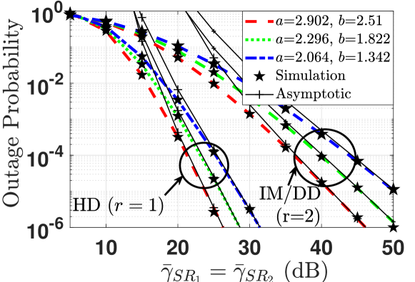
Figure 2 shows the OP versus SNR for the considered mixed dual-hop FSO-RF system, where (a(a=2.0642.0642.064; b𝑏b=1.342)1.342), (a(a=2.2962.2962.296; b𝑏b=1.822)1.822), and (a(a=2.9022.9022.902 ; b𝑏b=2.51)2.51) represent strong, moderate, and weak AT, respectively. We consider generalized HD (r𝑟r=111) and IM/DD (r𝑟r=222) techniques on S𝑆S-R𝑅R hop and H-ARQ with CC protocol transmission rounds N1subscript𝑁1N_{1}=333 and N2subscript𝑁2N_{2}=222 with γ¯RDsubscript¯𝛾𝑅𝐷\bar{\gamma}_{RD}=505050 dB. It can be observed that the OP improves from strong to weak AT condition. Further, it can be also noticed that the HD technique gives better outage performance compared to IM/DD technique. Moreover, we note that the OPs are 1.562×1071.562superscript1071.562\times 10^{-7} and 1.179×1091.179superscript1091.179\times 10^{-9} at γ¯SR2subscript¯𝛾𝑆subscript𝑅2\bar{\gamma}_{SR_{2}}=505050 dB and γ¯SR2subscript¯𝛾𝑆subscript𝑅2\bar{\gamma}_{SR_{2}}=606060 dB, respectively, for a𝑎a=2.2962.2962.296, b𝑏b=1.8221.8221.822, ξ𝜉\xi=1.21.21.2,

Refer to caption
Figure 5: Comparison of PER versus SNR under strong AT for H-ARQ with CC protocol and IM/DD technique.

N1subscript𝑁1N_{1}=333, N2subscript𝑁2N_{2}=222, and r𝑟r=222. Thus, the asymptotic slope is calculated as log10(1.562×10⁷)log10(1.179×10⁹)subscript101.562superscript107subscript101.179superscript109\log_{10}(1.562\times 10^{-7})-\log_{10}(1.179\times 10^{-9})=2.122.122.12 \approx N1min{ξ2/r,a/r,b/r}subscript𝑁1superscript𝜉2𝑟𝑎𝑟𝑏𝑟N_{1}\min\left\{\xi^{2}/r,a/r,b/r\right\}=N1ξ2/2subscript𝑁1superscript𝜉22N_{1}\xi^{2}/2. Likewise, the asymptotic slopes can be calculated and verified for other curves, which validates the asymptotic slope analysis conducted in Section III.D.

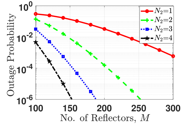
Figure 3 shows the effect of the number of IRS reflectors on the OP of the considered cascaded dual-hop FSO-RF communication system for for N1subscript𝑁1N_{1}=3 and various H-ARQ rounds on R𝑅R-D𝐷D link. We consider γ¯SR1subscript¯𝛾𝑆subscript𝑅1\bar{\gamma}_{SR_{1}}=454545 dB and γ¯RDsubscript¯𝛾𝑅𝐷\bar{\gamma}_{RD}=252525 dB on the S𝑆S-R𝑅R and R𝑅R-D𝐷D links, respectively. It can be seen that OP performance gets better with the increasing number of reflectors. Moreover, with increasing the H-ARQ transmission rounds, the OP performance improves.

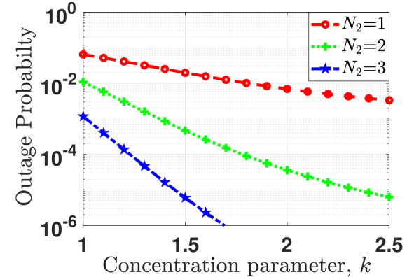
Figure 4 indicates the OP as a function of k𝑘k for γ¯SR1subscript¯𝛾𝑆subscript𝑅1\bar{\gamma}_{SR_{1}}=454545 dB and γ¯RDsubscript¯𝛾𝑅𝐷\bar{\gamma}_{RD}=404040 dB, where parameter k𝑘k is the concentration parameter of the von Mises distribution which reflects the accuracy of the phase error estimation [14]. It can be noticed that as parameter k𝑘k increases, the OP performance enhances.

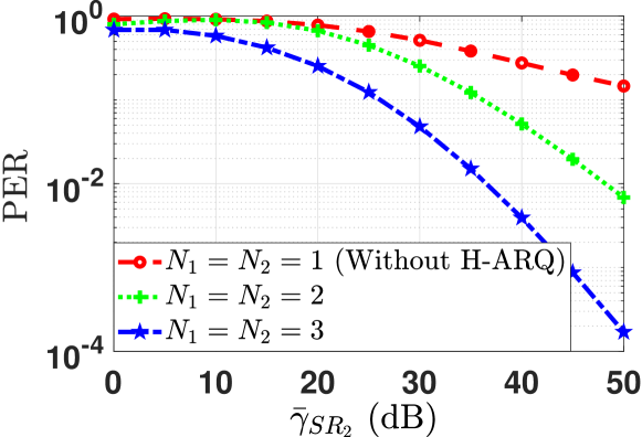
The PER versus SNR performance has been plotted for various number of H-ARQ transmission rounds in Figure 5, where we consider the packet length of 102410241024 bits and γ¯RDsubscript¯𝛾𝑅𝐷\bar{\gamma}_{RD}=454545 dB. It can be inferred that PER performance improves with the SNR on the FSO link. Moreover, the PER performance enhances as the H-ARQ transmission rounds increases.

Figure 6 indicates PER versus packet length for different values of γRDsubscript𝛾𝑅𝐷\gamma_{RD} and fixed γ¯SR2subscript¯𝛾𝑆subscript𝑅2\bar{\gamma}_{SR_{2}}=404040 dB. It is observed that as packet length increases, the PER performance slowly degrades and then saturates for higher packet lengths. Moreover, it is also seen that on increasing γ¯RDsubscript¯𝛾𝑅𝐷\bar{\gamma}_{RD} from 353535 dB to 454545 dB, the PER improves.

V Conclusions

In this letter, we investigated the performance of a mixed dual-hop FSO-RF system using IRS with phase error on the R𝑅R-D𝐷D link and H-ARQ protocol over both hops. We derive novel closed-form expressions of OP and PER for the considered system. Useful design insights into the system performance are obtained through the diversity analysis. The presented results comprehensively capture the impact of various system parameters such as AT, number of

Refer to caption
Figure 6: Comparison of PER versus packet length under strong AT for H-ARQ with CC protocol and IM/DD technique for γSR2subscript𝛾𝑆subscript𝑅2\gamma_{SR_{2}}=40 dB.

IRS reflectors, concentration parameter, H-ARQ rounds, and detection techniques on the outage and PER that are critical for the design of such mixed FSO-RF systems.

References

  • [1] M. A. Khalighi et al., “Survey on free space optical communication: A communication theory perspective,” IEEE Commun. Surveys Tuts., vol. 16, no. 4, pp. 2231–2258, Fourthquarter 2014.
  • [2] F. Yang et al., “Free-space optical communication with nonzero boresight pointing errors,” IEEE Trans. Commun., vol. 62, no. 2, pp. 713–725, February 2014.
  • [3] G. D. Verma et al., “Secrecy performance of FSO communication systems with non-zero boresight pointing errors,” IET Commun., vol. 15, no. 1, pp. 155–162, 2021.
  • [4] L. Yang et al., “Mixed dual-hop FSO-RF communication systems through reconfigurable intelligent surface,” IEEE Commun. Lett., vol. 24, no. 7, pp. 1558–1562, 2020.
  • [5] “3GPP TR38.885 V16.0.0 (38885-g00.zip), Study on NR Vehicle-to
    -Everything (V2X), https://www.3gpp.org/ftp/specs/archive/38_series
    /38.885,Accessed: 18-07-2021.”
  • [6] A. Mathur et al., “Performance of hybrid ARQ over power line communications channels,” in 2020 IEEE 91st . Veh. Technol. Conference (VTC2020-Spring), 2020, pp. 1–6.
  • [7] S. Ge et al., “Packet error rate analysis and power allocation for CC-HARQ over Rayleigh fading channels,” IEEE Commun. Lett., vol. 18, no. 8, pp. 1467–1470, 2014.
  • [8] Y. Xi et al., “A general upper bound to evaluate packet error rate over quasi-static fading channels,” IEEE Trans. Wireless Commun., vol. 10, no. 5, pp. 1373–1377, 2011.
  • [9] G. D. Verma et al., “Performance improvement of FSO communication systems using hybrid-ARQ protocols,” Appl. Opt., vol. 60, no. 19, pp. 5553–5563, Jul 2021.
  • [10] E. Bjornson et al., “Intelligent reflecting surface versus decode-and-forward: How large surfaces are needed to beat relaying?” IEEE Wireless Commun. Lett., vol. 9, no. 2, pp. 244–248, 2020.
  • [11] A. Sikri et al., “Reconfigurable intelligent surface for mixed FSO-RF systems with co-channel interference,” IEEE Commun. Lett., vol. 25, no. 5, pp. 1605–1609, 2021.
  • [12] Y. Ai et al., “On hybrid-ARQ-based intelligent reflecting surface-assisted communication system,” arXiv preprint arXiv:2009.10776, 2020.
  • [13] V. Jamali et al., “Intelligent surface-aided transmitter architectures for millimeter-wave ultra massive MIMO systems,” IEEE Open J. Commun. Soc., vol. 2, pp. 144–167, 2021.
  • [14] M.-A. Badiu et al., “Communication through a large reflecting surface with phase errors,” IEEE Wireless Commun. Lett., vol. 9, no. 2, pp. 184–188, 2020.
  • [15] Z. Ghassemlooy et al., Optical wireless communications: system and channel modelling with Matlab®.   CRC press, 2019.
  • [16] M. R. Bhatnagar et al., “Performance analysis of Gamma–Gamma fading FSO MIMO links with pointing errors,” J. Lightw. Technol., vol. 34, no. 9, pp. 2158–2169, 2016.
  • [17] I. S. Gradshteyn et al., Table of integrals, series, and products, 7th ed.   Elsevier/Academic Press, Amsterdam, 2007.
  • [18] L. Kong et al., “Effective rate evaluation of RIS-assisted communications using the sums of cascaded α𝛼\alpha-μ𝜇\mu random variates,” IEEE Access, vol. 9, pp. 5832–5844, 2021.
  • [19] A. Gupta et al., “Cascaded FSO-VLC communication system,” IEEE Wireless Commun. Lett., vol. 6, no. 6, pp. 810–813, 2017.
  • [20] A. P. Prudnikov et al., Integrals and Series of Special Functions. Vol.2.   RUS: Science, 1983.