Hybrid Reflection Modulation
Abstract
Reconfigurable intelligent surface (RIS)-empowered communication has emerged as a novel concept for customizing future wireless environments in a cost- and energy-efficient way. However, due to double path loss, existing fully passive RIS systems that purely reflect the incident signals into preferred directions attain an unsatisfactory performance improvement over the traditional wireless networks in certain conditions. To overcome this bottleneck, we propose a novel transmission scheme, named hybrid reflection modulation (HRM), exploiting both active and passive reflecting elements at the RIS and their combinations, which enables to convey information without using any radio frequency (RF) chains. In the HRM scheme, the active reflecting elements using additional power amplifiers are able to amplify and reflect the incoming signal, while the remaining passive elements can simply reflect the signals with appropriate phase shifts. Based on this novel transmission model, we obtain an upper bound for the average bit error probability (ABEP), and derive achievable rate of the system using an information theoretic approach. Moreover, comprehensive computer simulations are performed to prove the superiority of the proposed HRM scheme over existing fully passive, fully active and reflection modulation (RM) systems.
Index Terms:
Reconfigurable intelligent suraface (RIS), reflection modulation (RM), index modulation (IM), active RIS.I Introduction
Reconfigurable intelligent surface (RIS)-empowered communication technology which configures electromagnetic waves over-the-air to improve the received signal quality, appears to be a promising solution for future wireless transmission networks [1]. Particularly, RISs are planar metasurfaces that enable the modification of propagation environments via integrated smart programmable elements in favor of enhancing signal quality. By adjusting impinging signals, these elements are able to perform unique functions such as controlled reflection, amplification, absorption, etc. to boost the signal strength, alleviate the inter-channel interference and thus enhance the channel capacity gains [2].
The existing literature on RIS-aided systems is extensive and focuses particularly on RISs with fully passive reflecting elements that merely reflect the incident signal to desired directions by employing low-power electronic components [3]. In early RIS-aided transmission schemes, multi-user systems that optimize the transmit power [4, 5, 6], error performance [7, 8, 9], and achievable rate [10, 11, 12, 13] have been developed in order to achieve major performance gains. Further, an RIS is deployed for improving the physical layer security of target communication systems [14, 15, 16] while in [17, 18, 19], deep learning-based efficient solutions have been developed for channel estimation and reflection-based designs. Recently, leveraging RIS, realistic sub- GHz [20] and millimeter wave (mmWave) channel models [21, 22] are designed and implemented. Above all, unlike the aforementioned systems that consider computer simulations, in [23, 24, 25], low-cost RIS prototypes are constructed to obtain more accurate results about actual performance of the RIS-aided systems through experimental measurements.
Over the past decade, substantial research efforts have been devoted to the index modulation (IM) technique, one of the revolutionary transmission paradigms, which conveys extra information bits employing the building blocks of typical wireless communication systems, such as antennas, relays, antenna patterns, time slots, etc. [26]. On the other hand, the proliferation of literature on the RIS technology heightens the need for increasing data rates using IM techniques. Therefore, the combination of RISs with the traditional IM systems has been aroused in [27, 28, 20], where the information is transmitted via indices of transmit/receive antennas, and an RIS is adopted to further enhance transmission performance. Moreover, the performance analysis of the RIS-aided IM schemes has been investigated in [29, 30, 31] and novel closed form expressions are obtained in [32]. On the other hand, in recent studies, a novel IM technique, reflection modulation (RM), has been developed to utilize the reflecting elements as information transmitting units [33]. In recent RM systems, using ON/OFF keying mechanism of the passive reflection elements, an RIS has been deployed to carry information [34, 35, 36, 37].
Despite this extensive research, since RIS-aided systems suffer from a multiplicative path attenuation [38], it is practically very challenging, in case of strong direct link, for fully passive RISs to obtain a remarkable performance gain over a conventional wireless scenario, which is a major drawback to overcome.
On the other hand, more recent attention has focused on facilitating active reflecting elements at RISs to attain significant performance gains, which lays the groundwork for further research in RIS-aided transmission schemes [39, 40, 41, 42, 43, 44]. In [39], achievable channel capacity of a single-input single-output (SISO) system assisted by an RIS, whose reflecting elements are equipped with additional controllable power amplifiers to simultaneously amplify and reflect signals, has been elaborately analyzed through experimental measurements. Subsequently, in follow-up studies, channel capacity and energy efficiency of fully active RIS [41] and partially active RIS-aided systems [42] have been compared to the earlier benchmark studies of conventional specular reflection and fully passive RIS-aided systems. Reported results indicate a significant performance achievement for RIS-aided systems with active reflecting elements, compared to prior studies.
Against this background, this paper presents a novel IM scheme called hybrid reflection modulation (HRM) that utilizes a hybrid RIS which consists of both active and passive elements to support the transmission of a SISO system. In other words, the main motivation of this study is to combine the attractive advantages of IM and active RIS systems in a clever scheme in which the RIS operates as a part of the transmitter and directly transmits information. This makes the proposed scheme fundamentally different from the recent hybrid RIS-aided designs that consider the classical SISO signaling over a hybrid RIS architecture employing a certain number of active reflecting elements [40, 43]. In the proposed HRM scheme, we assume that the RIS elements are equipped with electronically controllable phase shifters and reflection-type amplifiers [39], which enable to simultaneously perform reflection and amplification functions. While the integrated phase shifters are dynamically adjusted to supply convenient phase shifts, the available power amplifiers can be turned ON and OFF according to incoming information bits to avoid excessive power consumption. Therefore, in the HRM scheme, in accordance with the incoming information bits, an RIS element can plainly reflect the incident signal without any amplification as a passive reflecting element or further amplify the reflected signal at the expense of increasing power consumption as an active reflecting element. On the other hand, by adapting the IM principle, the RIS is split into sub-groups, and the information is transmitted through different channel realizations created by various combinations of active and passive reflecting elements in these groups. Moreover, we perform a detailed theoretical analysis to obtain achievable rate expressions using an information theoretic approach, and derive an upper bound for the analytical bit error probability (ABEP) of the system. Furthermore, we carry out a comprehensive numerical analysis under spatially correlated and uncorrelated channel conditions to illustrate the performance improvement of the HRM scheme over the prior RIS-aided benchmark schemes considering fully active [39] and fully passive [1, 35] RISs.
The remaining of the paper proceeds as follows. The system model of the proposed HRM scheme is given in Section II. Section III provides theoretical performance analyses of the HRM scheme including ABEP, achievable rate and energy efficiency. In Section IV, computer simulation results are presented, and the conclusions are given in Section V.
Notations: Throughout this paper, vectors and matrices are denoted by bold lower and bold upper letters, respectively. Absolute value of a scalar is denoted by while is used for Euclidean/Frobenious norm. and stand for Hermitian and transposition operators, respectively. denotes distribution of a complex Gaussian random variable with mean and variance . represents a diagonal matrix with diagonal elements of , and denotes the set of dimensional complex matrices. Furthermore, , and represent probability of an event, -function and expectation operator, respectively.
II Hybrid Reflection Modulation
In this section, after giving the review of the classical passive and active RIS, we present the system model and the detection algorithm of the proposed HRM scheme.
II-A Passive and Active RIS
Most of the current literature on RIS-aided systems pays particular attention on RIS with passive reflecting elements in various research fields [1, 3, 2, 13, 4, 8, 9, 10, 11, 12, 5, 6, 7]. By smartly inducing convenient phase shifts without any transmit power consumption [4], the passive RIS elements do not directly modify the magnitude of the incident signal. On the other hand, the active reflecting elements are capable of generating reflection gains of greater than unity at the cost of additional power consumption [39, 42]. This amplification functionality of a reflecting element can be achieved by integrating additional power amplifier circuitry such as tunnel diode [42] or low-noise amplifier (LNA) [39]. Therefore, unlike a passive reflecting element, each active element introduces a non-negligible thermal noise. For instance, let and respectively represent the reflection gains of a passive and an active element whose magnitudes, (, ) and phases (, ) can be defined as follows
| (1) | |||
| (2) |
Nevertheless, although the active reflecting elements exploit power supplies in order to amplify the reflected signal, their hardware constructions are completely different from amplify-and-forward (AF) relays that utilize high-cost signal processing units.
II-B HRM Scheme
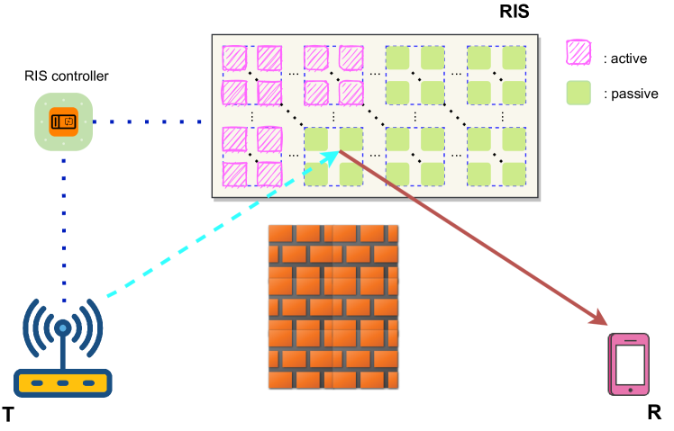
Adopting the IM principle, in the HRM scheme, we aim to modulate a single tone carrier signal through RIS with reflective and power controllable elements. As illustrated in Fig. 1, in the proposed HRM scheme, we consider a SISO system that employs an RIS with reflecting elements to boost the communication link between the transmitter (T) and the receiver (R) in an outdoor environment.111Since the MIMO extension of the proposed HRM scheme requires the development of a computationally intensive algorithm for optimization of reflection coefficients of the RIS elements, this paper considers a SISO transmission to avoid an additional computational burden at the RIS. In practical conditions, since it is unlikely to maintain a constant direct link between T-R link due to severe signal blockage in an outdoor environment, we assume that the direct link is blocked by the obstacles. Moreover, an RIS controller is incorporated with the RIS to dynamically adjust the phase shifts and the amplification gains of each reflecting element considering the information provided from the transmitter via a wireless control channel. For the sake of simplicity, we assume that perfect channel state information (P-CSI) of the all nodes are available at the transmitter [4], which are conveyed to the RIS controller via the control link, and to the receiver through pilot-based transmission [45]. However, since the reflection amplitudes and phases are controlled separately, comparing to fully passive RIS [37], the RIS controller requires additional variable resistor loads [46].
 /passive
  )
)Subsequently, unlike the conventional passive elements that only utilize low-cost PIN diodes or varactors [3] to simply reflect signals without any amplification, the HRM scheme additionally includes a reflection-type power amplifier per RIS element to amplify the reflected signals in order to attain further channel capacity gains [39]. In the HRM scheme, a phase shifter per each RIS element is employed to generate optimum phase shift for maximizing the signal-to-noise ratio (SNR), while reflection-type power amplifiers are dynamically turned ON/OFF according to the transmitted information bits. Therefore, similar to conventional RIS architecture, when the power amplification option is disabled, an RIS element can merely reflect the incident signal without any amplification, or when enabled, it can further amplify the signal with a convenient phase shift. Notably, the RIS element corresponds to a conventional passive reflecting element in the former case, while it is converted to an active reflecting element in the latter case.
In the proposed HRM scheme, the RIS with reflecting elements is divided into sub-groups, each having number of RIS elements. Then, applying the IM concept, the HRM scheme transmitting a single tone carrier signal requires information bits to employ the elements of out of groups as active reflecting elements while the remaining ones are used as passive reflecting elements, where . Therefore, the numbers of active and passive reflecting elements become and , respectively. In particular, for , since the power amplifiers of all reflecting elements are disabled, the RIS elements simply reflect signals without any amplification. In that case, the RIS serves as a conventional fully passive RIS.
Indeed, since active RIS elements further amplify the incident signal compared to the conventional passive reflecting elements, in the HRM scheme, exploiting a different number of active RIS elements in each time instant generates multi-level HRM symbols , like a virtual amplitude shift keying (ASK) modulator. Moreover, unlike the classical ASK modulator that utilizes a fully digital RF chain with high hardware complexity and implementation cost, in the proposed HRM scheme, employing an unmodulated cosine carrier at the transmitter, different combinations of active and passive reflecting elements are used to create a virtual ASK constellation. This also facilitates the HRM receiver to differentiate the perceived signal with a high accuracy.
| Information Bits | ||||
| Number of active RIS groups () | ||||
| HRM symbol () |
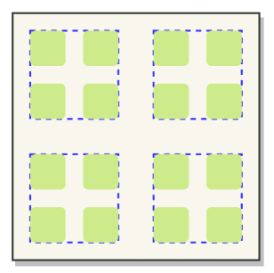
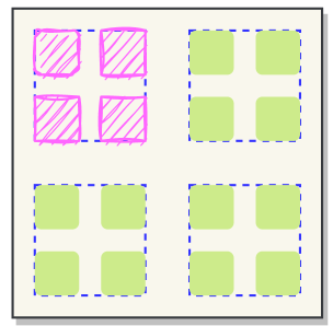
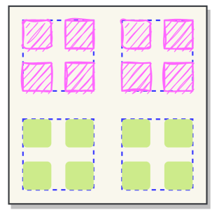
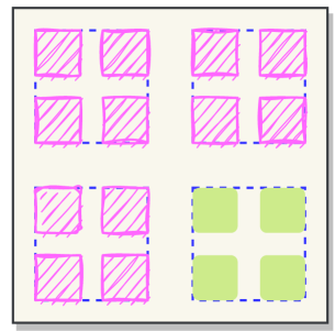
To better illustrate, the HRM transmission scheme is explained with following example. In order to achieve a spectral efficiency of bits per second per Hertz (bits/s/Hz), we assume that the proposed HRM transmission scheme employs an RIS with elements divided into sub-groups, each of which consisting RIS elements. While the active/passive RIS element combinations for the corresponding HRM symbols are presented in Fig. 2, the considered bit mapping is listed in Table I, where . As clearly seen from Fig. 2, unlike the conventional fully passive [1] and fully active RISs [39] whose elements continuously operate in the same manner, in the proposed HRM scheme, via adjusting power amplifiers, different RIS configurations consisting of active and passive elements are formed in each time instant, which creates distinct variations in the amplitude of the over-the-air HRM symbols. Accordingly, for incoming bits, since the number of active RIS sub-groups is , symbol is created by a fully passive RIS, while for the other incoming bit streams of , and , the HRM symbols are generated from hybrid RIS configurations consisting of both active and passive reflecting elements. Clearly, the larger number of active sub-groups, the further RIS amplifies the incident signal.
Let be the reflection coefficient of the -th reflecting element of the HRM scheme with magnitude and phase shift , where . Then, for active and passive elements, the reflection coefficient becomes
| (3) |
It is worth noting that for the passive reflecting elements, the reflection gain is assumed to be [1] while for the active reflecting elements, it is [39, 40, 41, 42, 43]. For simplicity, we assume that all active reflecting elements have the same reflection gain, i.e., for . Accordingly, the reflection matrices including the phases of the active and passive elements can be respectively given as and .
Let and be the channel vectors between the T-RIS and RIS-R links, respectively, where and are the path attenuation in the corresponding links. Here, the path loss terms are obtained for the T-RIS distance and the RIS-R distance as and , where is the path loss at the reference distance of meter (m), and and are the path loss exponents at the T-RIS and RIS-R links, respectively. Please note that T and R are located sufficiently away and operate independently, thus, the T-RIS and RIS-R links are statistically independent, where and are modeled as independent Rician fading channels and generated as
| (4) | |||
| (5) |
where and are the line-of-sight (LOS) components and and are non-LOS (NLOS) components of their corresponding channel vectors, while and are the Rician fading coefficients of the T-RIS and RIS-R links, respectively. Here, both the LOS and NLOS components are assumed to consist of complex Gaussian random variables, whose each entry is independent and identically distributed (i.i.d.) and follows distribution.
For a better illustration, the channel vectors between the T-RIS and RIS-R links can be given as and , respectively, where and are the channel vectors corresponding to the active elements, while the channel vectors and correspond to the passive reflecting elements at the RIS. Therefore, for being the total transmit power, the overall received complex baseband signal at the receiver becomes [39]:
| (6) |
where is the static noise term, while is the additional noise vector composing the thermal noise terms generated by power amplifiers of active elements that cannot be neglected as in the passive elements.
In the HRM scheme, the phase shifts of the all reflection elements and the amplification gain of the active RIS elements can be optimized in order to achieve the maximum SNR. Then, for being the maximum amplification power at the RIS, which corresponds to the power budget of active reflecting elements [40], the maximum instantaneous received SNR can be formulated as
| (7) | |||
| (8) |
Then, applying the triangle and Cauchy-Schwarz inequalities [47], since , the optimum phase shift of the -th reflecting element, , which completely eliminates the phases of the corresponding channel coefficients, and the reflection gain are simply obtained as
| (9) | |||
| (10) |
Therefore, for and respectively being the -th component of the channel vectors and , for the optimum phase shifts in (9) and an arbitrary amplification gain , the received signal (6) can be rewritten as
| (11) |
where , and is the -th complex element of the dynamic noise vector . Therefore, for being the HRM symbol for the corresponding , the received signal can be rewritten as
| (12) |
where is the overall noise term. It is worthy to note that applying the central limit theorem (CLT) for increasing , is approximated to a complex Gaussian random variable with distribution, where 222For and being independent random variables, the variance of the product is calculated as and the mean of is . In addition, the mean and variance of the sum are and , respectively..
II-C HRM Receiver
In the HRM scheme, since exploiting different number of active reflecting elements creates virtual amplitude variations in the received signal, different signal levels of the HRM symbols can be easily distinguished at the receiver. Moreover, the HRM receiver with perfect knowledge of the overall channel considers maximum likelihood (ML) detection algorithm to choose the most likely estimate of , as follows
| (13) |
where is the conditional probability density function (pdf) of the received signal given , which can be given as
| (14) |
Here, the overall noise power , where it is obtained as in the previous subsection, and the HRM symbol vary with the number of active sub-groups of RIS () and the total number of active reflecting elements . However, since the thermal noise of each active element experiences the path attenuation of the RIS-R link () while the RIS-R distance of is sufficiently large, the varying hardly affects the decision of minimum metrics in (14). Therefore, the HRM receiver can simply detect as follows
| (15) |
which gives as almost the same estimate as the ML algorithm given in (13). Here, we consider all combinations of active and passive elements and simply select the closest virtual constellation point with respect to received signal.
II-D Fully Hybrid Reflection Modulation (F-HRM)
In this subsection, a special case of the proposed HRM scheme, fully hybrid reflection modulation (F-HRM), is introduced. In the F-HRM scheme, the same RIS, transmitter and receiver hardware architectures of the HRM scheme are considered. However, unlike HRM, in the F-HRM scheme, whole RIS elements without grouping are assumed to manipulate the incident signal in the same manner. Specifically, in the F-HRM scheme, -bit information ( bits/s/Hz) is transmitted over the RIS to control the amplification gains of the RIS elements. In the F-HRM scheme, by properly adjusting power amplifier of each reflecting element, for the incoming bit, all reflecting elements perform a plain passive reflection with the optimum phase shifts of (9), while for the incoming bit , all elements function as active reflecting elements that amplify and reflect the incident signal with additional thermal noise. Please note that, in the F-HRM scheme, since RIS elements operate in the same manner as a whole, number of the overall active reflection elements is for . Accordingly, in the F-HRM scheme, for the corresponding and values, the received signal, the optimum estimate of at the receiver and the maximum received SNR can be obtained from (11), (15) and (7)-(10), respectively.
III Performance Analyses
In this section, we investigate the performance of the proposed HRM in terms of average bit error probability (ABEP), achievable rate and energy efficiency.
III-A ABEP Analysis
In this subsection, the ABEP of the proposed HRM scheme is analyzed. Since the simple HRM detection algorithm in (15) gives exactly the same error performance as the true ML detector in (13), we build our theoretical analysis based on it in the following way.
After the pairwise error probability (PEP) of the HRM scheme is obtained, we derive the ABEP of the system using a moment generating function (MGF)-based approach [48]. For this purpose, first of all, in order to determine the conditional PEP (CPEP) of the HRM scheme, we assume that the number of sub-groups of active elements and its corresponding total number of active elements are erroneously detected as and , respectively. Therefore, considering the detection rule in (15), the CPEP of the HRM scheme can be given as
| (16) |
where is the HRM symbol for the corresponding . Therefore, the CPEP in (16) can be simplified to:
| (17) |
After some mathematical manipulations, the CPEP expression in (17) can be rewritten as
| (18) |
Therefore, for being a Gaussian random variable with , the CPEP expression yields in
| (19) |
where the mean and the variance of are calculated as and . After deriving the statistical distributions, the CPEP expression can be given, using -function, as
| (20) |
In the HRM scheme, the channel magnitudes of and are independent Rician distributed random variables with the means of and , and the variances of and , where is the Laguerre polynomial [49]. Then, defining , which is another Gaussian random variable with the following statistics
| (21) |
for the average error probability of the system is calculated in the following way. Considering the following alternative representation of -function
| (22) |
and using the MGF of , which follows non-central chi-square distribution, the average PEP can be calculated as follows
| (23) |
Here, the MGF of non-central chi-square distribution is given as [50]
| (24) |
Therefore, substituting the MGF expression (24) into (25), the PEP is obtained as
| (25) |
To gain further insights, since a function of has a single minimum at , where , by letting , (25) can be upper bounded as follows [48]
| (26) |
Moreover, for high regime, an asymptotic PEP expression can be approximated as:
| (27) |
It is worth noting that for , the PEP results the ABEP of the HRM scheme, while for the following well-known upper bound is considered [48]:
| (28) |
where is the number of bit errors in each PEP event.
III-B Achievable Rate Analysis
In this subsection, considering an information theoretic approach, we perform achievable rate analysis of the HRM scheme by deriving the mutual information (MI) between its transmit and received signals.
In the HRM scheme, since the an unmodulated carrier signal is transmitted and the information bits are modulated to generate a spatial constellation symbol , the MI of the HRM scheme corresponds to the information conveyed between the received signal vector space and spatial constellation space . Therefore, the achievable rate of the proposed HRM scheme becomes [50]
| (29) |
Here, since each HRM symbol is equiprobable, i.e., , substituting the conditional pdf of given in (14) into (29), the achievable rate of the HRM scheme is rewritten as
| (30) |
Therefore, after some algebraic manipulations, (30) can be simplified to [51]
| (31) |
III-C Energy Efficiency
In this subsection, the power consumption model and energy efficiency of the proposed HRM scheme are evaluated. In the HRM scheme, for being the transmit power efficiency, its average power consumption can be calculated as
| (32) |
where represents the overall power dissipated in transmitter and receiver circuit blocks while denotes the total power consumption of the RIS that can be given, for and respectively denoting the average number of active and passive reflecting elements, as follows:
| (33) |
In (33), and correspond to dynamic and static power consumption of the active reflecting elements, respectively, while is the required power per passive reflecting element [40], and is amplifier efficiency of the active reflecting elements for [40]. On the other hand, when a conventional RIS of passive reflecting elements is considered, corresponds to the power consumed by the adaptive phase shifters, i.e. [6], while for fully active RIS, whose elements include both reflection and amplification circuitry, the overall power consumed by the RIS becomes [40]. Comparing the power consumption of the proposed hybrid, fully active and fully passive RIS configurations, with the note that , it is obvious that fully passive RIS architectures with only reflection capabilities are the most power-efficient constructions. On the other hand, in the proposed HRM scheme, the hybrid RIS architectures save a significant amount of power compared to the fully active RIS designs.
Further, the energy efficiency in bits per Joule (bits/J) of the HRM system results, in terms of instantaneous received SNR given in (7), can be obtained as
| (34) |
where represents the system bandwidth.
IV Numerical Results
In this section, the BER, achievable rate and energy efficiency performance of the proposed HRM scheme is investigated through extensive computer simulations. For different number of RIS sub-groups and reflecting elements, the superior performance of the proposed HRM scheme over the existing fully active [39], fully passive [1] and RM [35] schemes is demonstrated. Unless otherwise indicated, in all simulations, the following system parameters are assumed: the distances m and m, the scale parameters the path loss exponents and , the Rician shape parameters , the noise variances dBm, and the reference path loss value of dB.
IV-A BER Performance in Ideal Channel Conditions
In this subsection, the BER performance of the proposed HRM scheme under the ideal channel conditions is carried out.
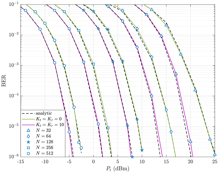
In Fig. 3, the analytical and numerical results of the BER performance of the HRM scheme with , which achieves a spectral efficiency of bits/s/Hz for and Rician scale factors of , is demonstrated. As it can be clearly seen from Fig. 3, the analytical results applying the CLT for perfectly match to computer simulations. Moreover, it is observed that for each , doubling the reflection elements provides approximately dBm improvement in the required transmit power at the BER value of .
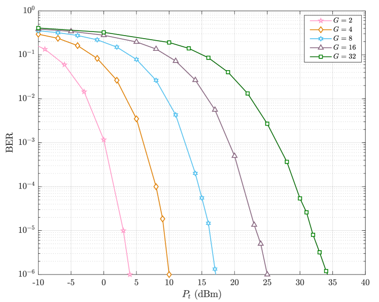
In Fig. 4, the BER performance of the HRM scheme, is given for reflecting elements divided into and sub-groups. It is observed that like the ordinary multi-level digital modulation techniques, as the number of sub-groups is increased the signal levels of the HRM symbols get closer, and this deteriorates the BER performance of the HRM scheme. In particular, it is apparent that the HRM scheme achieving bits/s/Hz () with an RIS of sub-groups exhibits remarkably worse error performance compared to the lower cases, which shows an interesting trade-off between the error performance and the spectral efficiency. Moreover, as in the classical ASK modulation, considering the reflection power constraint in (8), since the same and values are considered in Fig. 4, the systems with larger necessitate a higher power consumption. Therefore, it can be concluded that besides their superior error performance, the HRM systems with a smaller save more energy than the systems with a larger .
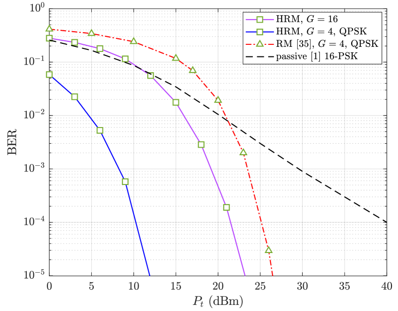
In Fig. 5, the BER performance comparison of HRM, RM [35] and conventional fully passive RIS-aided systems is investigated for . In the reference RM scheme [35], similar to HRM, an RIS with fully passive reflecting elements, is split into sub-groups whose indices are used to convey additional information bits. However, contrary to HRM and conventional fully passive RIS-aided systems, adjusting ON/OFF keying states of each group, the whole RIS elements are not utilized in the reference RM transmission scheme [35]. Moreover, in the reference RM scheme [35], an RF source is used to transmit an optimized -ary phase shift keying (-PSK) constellation per each RIS configuration to achieve a spectral efficiency of . Then, in Fig. 5, to attain bits/s/Hz, considering the optimum phase shifts in (9), the HRM scheme with sub-groups and the amplification gain of is compared to the reference fully passive RIS-aided system with -PSK, and the RM scheme with sub-groups employing the rotated quadrature PSK (QPSK) [35]. The results show that although the HRM scheme with enlarges the HRM signal constellation considerably, it still achieves significant performance over the RM [35] and conventional fully passive RIS-aided system. Furthermore, in Fig. 5, at bits/s/Hz, as an extension of the HRM scheme, the BER performance of HRM that jointly encodes information in the transmit signal and RIS sub-groups is also evaluated. In this case, while preserving the RIS and receiver architecture of the proposed HRM, instead of an unmodulated signal, a QPSK modulated signal is employed at the transmitter of the HRM scheme. For the case of the HRM scheme with -PSK modulation, the spectral efficiency becomes bits/s/Hz. Therefore, in order to achieve a spectral efficiency of bits/s/Hz, for and QPSK signaling, the RIS is clustered into sub-groups. The results exhibit that the HRM scheme with and QPSK signal transmission achieves dB gain at the BER value of over the reference RM scheme [35]. It is clear from the Fig. 5 that using an additional RF chain at the transmitter alleviates the burden of RIS transmission by reducing the required number of RIS sub-groups. In that case, since the benefits of a lower HRM signal level are retained, the BER performance improves, but it brings an additional hardware cost.
IV-B BER Performance in Non-Ideal Channel Conditions
In this subsection, the BER performance of the ideal and non-ideal channel conditions is compared for different RIS configurations.
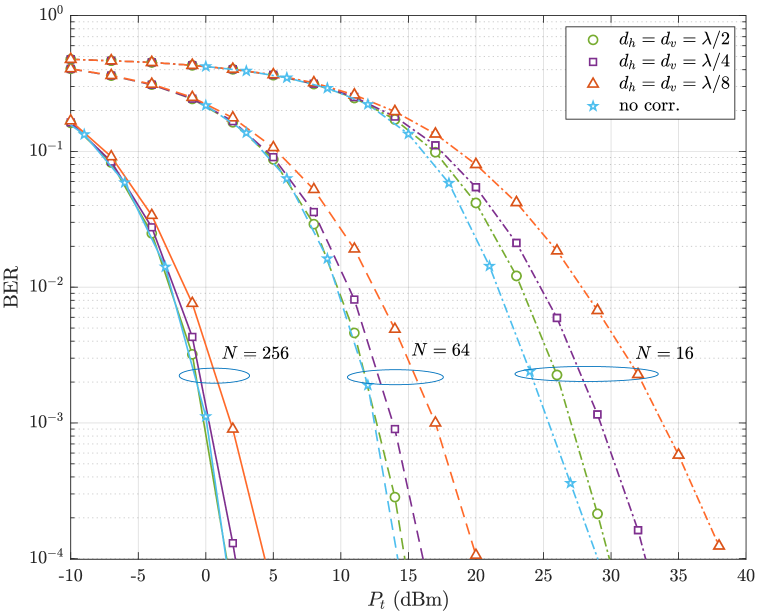
Further, for more realistic settings, we investigate the performance of the HRM scheme under the spatially correlated RIS elements whose impact on the BER performance is given in Fig. 6. For this aim, we consider a square RIS and assume that the channel vectors and , representing T-RIS and RIS-R links, respectively, are modeled as spatially correlated Rayleigh fading channels, i.e., in (4) and (5), and generated as
| (35) | |||
| (36) |
where is the correlation matrix due to spatially correlated RIS elements, whose -th component is [52, 53], for and being the wavelength at GHz operating frequency. Here, the horizontal width and vertical height of a single reflecting element are represented by and , respectively, and for , the vector , where is the number of reflecting elements in each row or column of the square RIS, i.e., .
In Fig. 6, the BER performance of HRM scheme under spatially correlated and spatially independent channel conditions is given for the squared RIS elements with different dimensions of at the spectral efficiency of bits/s/Hz. The results show that the configuration of the RIS has a great impact on the degree of correlation. Therefore, as the horizontal and vertical sizes of the RIS elements enlarge, the HRM system becomes more robust to the bit errors. Moreover, it can also be deduced that increasing number of reflecting elements significantly facilitates the BER performance degradation of channel correlation. As it can be clearly seen from the Fig. 6, the HRM scheme with exhibits almost the same BER performance in both spatially correlated RIS with and spatially independent RIS cases. However, for the lower values, i.e., and , the spatial correlation causes a considerable deterioration in the BER performance.
IV-C Achievable Rate and Energy Efficiency Performance
In this subsection, the achievable rate and the energy efficiency performances of the proposed HRM scheme and the fully passive and fully active RIS-aided systems are compared through extensive computer simulations.
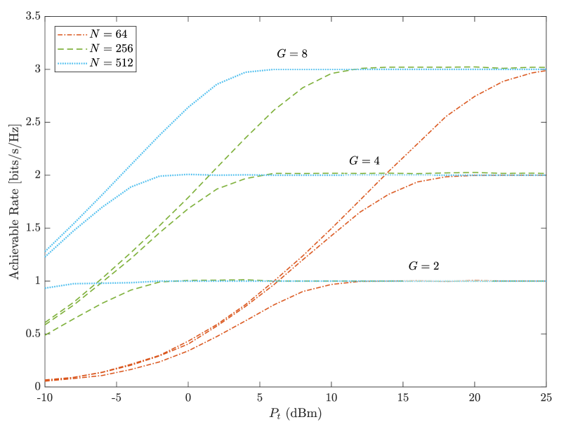
Fig. 7 provides the achievable rate of the HRM scheme with the amplification gain of the active elements being . In this figure, the RIS with and reflecting elements are divided into and sub-groups that achieve the spectral efficiency values of and bits/s/Hz, respectively. These information theoretic results illustrate that increasing number of reflecting elements, , enables a more rapid convergence to the target data rate.
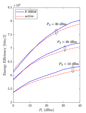
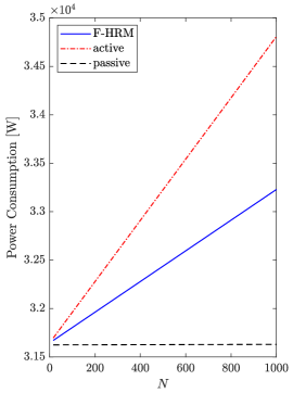
Furthermore, in Fig. 8, we investigate the energy efficiency and power consumption of F-HRM, fully active [39] and fully passive RIS-aided schemes [1] at the spectral efficiency of bits/s/Hz. At the transmitter, while in the F-HRM scheme, an unmodulated carrier signal is considered, binary PSK (BPSK) modulation is employed in the fully passive and fully active RIS-aided systems. Notably, in the F-HRM scheme, the average number of active and passive elements are equal as . Therefore, to evaluate the total power consumption in (33), we set dBm, mW, dBm, dBm, and [40], and assume MHz [6] to determine the energy efficiency of (34) by number of iterations.
In Fig. 8(a), the energy efficiency of F-HRM and active RIS-aided transmission schemes, all employing reflecting elements at the RIS, is measured as a function of . The results indicate a considerable energy efficiency improvement for the F-HRM scheme over the active RIS-aided system for and dBm. These results can be explained by the fact that although a fully active RIS-aided system achieves substantial capacity gains [39, 41], it requires larger amount of power compared to the more environment-friendly F-HRM scheme.
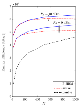
In addition, in Fig. 8(b), the energy efficiency of the F-HRM and active and passive RIS-aided systems are further investigated for varying values and the amplification power of and dBm, as well as for the transmit power dBm. Consistent with the results in Fig. 8(a), the F-HRM scheme achieves a noticeable improvement in the energy efficiency compared to fully active RIS-aided system, and exceeds the conventional passive RIS-aided system with a substantial margin. To support these results, in Fig. 8(c), the power consumption of the proposed F-HRM scheme and the reference RIS-aided systems are depicted as a function of for dBm and dBm. Obviously, increasing hardly changes the power consumption of the passive RIS-aided systems, while further opens the power consumption gap between the F-HRM and active RIS-aided systems.
The results presented in Fig. 8 are in accordance with the earlier studies [39, 41, 40] that an interesting trade-off exists between the achievable rate and power consumption. Therefore, the RIS-aided systems with partially or fully active reflecting elements are capable to achieve ultimate capacity gains compared to the conventional reflection-based transmission schemes such as fully passive RIS-aided systems. On the other hand, although the HRM and fully active RIS-aided systems have the same hardware capabilities, i.e., the all reflecting elements are integrated with additional power amplifiers, since constantly driving active RIS elements requires a tremendous power consumption, more energy-efficient communication systems with high data rate can be constructed using HRM transmission concepts that limit the overall power consumption. In summary, it can be deduced from the results that the HRM scheme offers an intermediate solution between a fully passive and fully active RIS-aided transmission scheme, and achieves noticeable performance gains with a high data rate in a more energy-efficient manner.
V Conclusion
In this paper, we have introduced the novel scheme of HRM which offers a promising solution for the RIS-aided transmission systems that experience high path attenuation. In the proposed HRM scheme, the target RIS has been split into sub-groups through which the conventional IM technique has been applied to transmit information. While the active/passive combinations of the reflecting elements in those sub-groups have been determined according to incoming information bits, the phases have been optimally adjusted for achieving maximum SNR gains. Therefore, the RIS has been configured to perform amplification and reflection functions at the same time. Besides, the analytical BER performance and the achievable rate of the HRM scheme have been derived. Furthermore, comprehensive computer simulations have been conducted to illustrate the performance achievement of the HRM scheme over the existing fully active, fully passive and RM systems. Moreover, the effect of hardware impairments and channel estimation errors on the BER performance of the proposed scheme, the generalization of HRM for non-uniform power distributions, new I/Q modulator designs and the MIMO/multi-user extension of the proposed scheme to increase its data rate, which requires the development of a sub-optimal detector to optimize the reflection coefficients of RIS elements, are interesting directions for future research.
References
- [1] E. Basar, “Transmission through large intelligent surfaces: A new frontier in wireless communications,” in Proc. IEEE European Conf. Netw. Commun. (EuCNC), Valencia, Spain, June 2019, pp. 112–117.
- [2] M. Di Renzo, A. Zappone, M. Debbah, M.-S. Alouini, C. Yuen, J. De Rosny, and S. Tretyakov, “Smart radio environments empowered by reconfigurable intelligent surfaces: How it works, state of research, and the road ahead,” IEEE J. Sel. Areas Commun., vol. 38, no. 11, pp. 2450–2525, July 2020.
- [3] E. Basar, M. Di Renzo, J. De Rosny, M. Debbah, M.-S. Alouini, and R. Zhang, “Wireless communications through reconfigurable intelligent surfaces,” IEEE Access, vol. 7, pp. 116 753–116 773, Aug. 2019.
- [4] C. Huang, A. Zappone, G. C. Alexandropoulos, M. Debbah, and C. Yuen, “Reconfigurable intelligent surfaces for energy efficiency in wireless communication,” IEEE Trans. Wireless Commun., vol. 18, no. 8, pp. 4157–4170, June 2019.
- [5] Z. Yang, M. Chen, W. Saad, W. Xu, M. Shikh-Bahaei, H. V. Poor, and S. Cui, “Energy-efficient wireless communications with distributed reconfigurable intelligent surfaces,” IEEE Trans. Wireless Commun., vol. 21, no. 1, pp. 665–679, Jan. 2022.
- [6] E. Björnson, Ö. Özdogan, and E. G. Larsson, “Intelligent reflecting surface versus decode-and-forward: How large surfaces are needed to beat relaying?” IEEE Wireless Commun. Lett., vol. 9, no. 2, pp. 244–248, Oct. 2019.
- [7] R. Liu, H. Li, M. Li, and Q. Liu, “Symbol-level precoding design for intelligent reflecting surface assisted multi-user mimo systems,” in Proc. IEEE 11th Int. Conf. Wireless Commun. Signal Process. (WCSP), Xi’an, China, Dec. 2019, pp. 1–6.
- [8] J. Ye, S. Guo, and M.-S. Alouini, “Joint reflecting and precoding designs for ser minimization in reconfigurable intelligent surfaces assisted MIMO systems,” IEEE Trans. Wireless Commun., vol. 19, no. 8, pp. 5561–5574, May 2020.
- [9] R. C. Ferreira, M. S. Facina, F. A. De Figueiredo, G. Fraidenraich, and E. R. De Lima, “Bit error probability for large intelligent surfaces under double-Nakagami fading channels,” IEEE Open J. Commun. Soc., vol. 1, pp. 750–759, May 2020.
- [10] M. Jung, W. Saad, Y. Jang, G. Kong, and S. Choi, “Performance analysis of large intelligent surfaces (LISs): Asymptotic data rate and channel hardening effects,” IEEE Trans. Wireless Commun., vol. 19, no. 3, pp. 2052–2065, Jan. 2020.
- [11] S. Zhang and R. Zhang, “Capacity characterization for intelligent reflecting surface aided MIMO communication,” IEEE J. Sel. Areas Commun., vol. 38, no. 8, pp. 1823–1838, June 2020.
- [12] B. Di, H. Zhang, L. Song, Y. Li, Z. Han, and H. V. Poor, “Hybrid beamforming for reconfigurable intelligent surface based multi-user communications: Achievable rates with limited discrete phase shifts,” IEEE J. Sel. Areas Commun., vol. 38, no. 8, pp. 1809–1822, June 2020.
- [13] Q. Wu and R. Zhang, “Intelligent reflecting surface enhanced wireless network via joint active and passive beamforming,” IEEE Trans. Wireless Commun., vol. 18, no. 11, pp. 5394–5409, Aug. 2019.
- [14] M. Cui, G. Zhang, and R. Zhang, “Secure wireless communication via intelligent reflecting surface,” IEEE Wireless Commun. Lett., vol. 8, no. 5, pp. 1410–1414, May 2019.
- [15] S. Hong, C. Pan, H. Ren, K. Wang, and A. Nallanathan, “Artificial-noise-aided secure MIMO wireless communications via intelligent reflecting surface,” IEEE Trans. Commun., vol. 68, no. 12, pp. 7851–7866, Sept. 2020.
- [16] J. Chen, Y.-C. Liang, Y. Pei, and H. Guo, “Intelligent reflecting surface: A programmable wireless environment for physical layer security,” IEEE Access, vol. 7, pp. 82 599–82 612, June 2019.
- [17] A. Taha, M. Alrabeiah, and A. Alkhateeb, “Deep learning for large intelligent surfaces in millimeter wave and massive MIMO systems,” in Proc. IEEE Global Commun. Conf. (GLOBECOM), Waikoloa, HI, USA, Feb. 2019, pp. 1–6.
- [18] C. Huang, R. Mo, and C. Yuen, “Reconfigurable intelligent surface assisted multiuser MISO systems exploiting deep reinforcement learning,” IEEE J. Sel. Areas Commun., vol. 38, no. 8, pp. 1839–1850, Aug. 2020.
- [19] C. Huang, G. C. Alexandropoulos, C. Yuen, and M. Debbah, “Indoor signal focusing with deep learning designed reconfigurable intelligent surfaces,” in Proc. IEEE 20th Int. Workshop Signal Process. Advances Wireless Commun. (SPAWC), Cannes, France, Aug. 2019, pp. 1–5.
- [20] Z. Yigit, E. Basar, and I. Altunbas, “SimMBM channel simulator for media-based modulation systems,” in Proc. IEEE 32nd Int. Symp. Personal, Indoor and Mobile Radio Commun. (PIMRC), Helsinki, Finland, Sept. 2021, pp. 1–6.
- [21] E. Basar, I. Yildirim, and F. Kilinc, “Indoor and outdoor physical channel modeling and efficient positioning for reconfigurable intelligent surfaces in mmwave bands,” IEEE Trans. Commun., vol. 69, no. 12, Dec. 2021.
- [22] E. Basar and I. Yildirim, “Reconfigurable intelligent surfaces for future wireless networks: A channel modeling perspective,” IEEE Wireless Commun., vol. 28, no. 3, pp. 108 – 114, Apr. 2021.
- [23] L. Dai, B. Wang, M. Wang, X. Yang, J. Tan, S. Bi, S. Xu, F. Yang, Z. Chen, M. Di Renzo et al., “Reconfigurable intelligent surface-based wireless communications: Antenna design, prototyping, and experimental results,” IEEE Access, vol. 8, pp. 45 913–45 923, Mar. 2020.
- [24] G. C. Trichopoulos, P. Theofanopoulos, B. Kashyap, A. Shekhawat, A. Modi, T. Osman, S. Kumar, A. Sengar, A. Chang, and A. Alkhateeb, “Design and evaluation of reconfigurable intelligent surfaces in real-world environment,” IEEE Open J. Comm. Soc., vol. 3, pp. 462–474, Mar. 2022.
- [25] R. Fara, P. Ratajczak, D.-T. Phan-Huy, A. Ourir, M. Di Renzo, and J. De Rosny, “A prototype of reconfigurable intelligent surface with continuous control of the reflection phase,” IEEE Wireless Comm., vol. 29, no. 1, pp. 70–77, Feb. 2022.
- [26] E. Basar, M. Wen, R. Mesleh, M. Di Renzo, Y. Xiao, and H. Haas, “Index modulation techniques for next-generation wireless networks,” IEEE Access, vol. 5, pp. 16 693–16 746, Aug. 2017.
- [27] E. Basar, “Reconfigurable intelligent surface-based index modulation: A new beyond MIMO paradigm for 6G,” IEEE Trans. Commun., vol. 68, no. 5, pp. 3187–3196, May 2020.
- [28] A. E. Canbilen, E. Basar, and S. S. Ikki, “Reconfigurable intelligent surface-assisted space shift keying,” IEEE Wireless Commun. Lett., vol. 9, no. 9, pp. 1495–1499, Sept. 2020.
- [29] T. Ma, Y. Xiao, X. Lei, P. Yang, X. Lei, and O. A. Dobre, “Large intelligent surface assisted wireless communications with spatial modulation and antenna selection,” IEEE J. Sel. Areas Commun., vol. 38, no. 11, pp. 2562–2574, July 2020.
- [30] Q. Li, M. Wen, S. Wang, G. C. Alexandropoulos, and Y.-C. Wu, “Space shift keying with reconfigurable intelligent surfaces: Phase configuration designs and performance analysis,” IEEE Open J. Commun. Soc., vol. 2, pp. 322–333, Feb. 2021.
- [31] U. Singh, M. R. Bhatnagar, and A. Bansal, “RIS-Assisted SSK Modulation: Reflection Phase Modulation and Performance Analysis,” IEEE Commun. Lett., vol. 26, no. 5, pp. 1012–1016, Mar. 2022.
- [32] S. P. Dash, R. K. Mallik, and N. Pandey, “Performance Analysis of an Index Modulation-Based Receive Diversity RIS-Assisted Wireless Communication System,” IEEE Commun. Lett., vol. 26, no. 4, pp. 768–772, Apr. 2022.
- [33] S. Guo, S. Lv, H. Zhang, J. Ye, and P. Zhang, “Reflecting modulation,” IEEE J. Sel. Areas Commun., vol. 38, no. 11, pp. 2548–2561, July 2020.
- [34] S. Lin, B. Zheng, G. C. Alexandropoulos, M. Wen, M. Di Renzo, and F. Chen, “Reconfigurable intelligent surfaces with reflection pattern modulation: Beamforming design and performance analysis,” IEEE Trans. Wireless Commun., vol. 20, no. 2, pp. 741–754, Oct. 2020.
- [35] Y. Hussein, M. Assaad, and H. Sari, “Reconfigurable intelligent surface index modulation with signature constellations,” in Proc. IEEE Wireless Commun. Netw. Conf. (WCNC), Nanjing, China, Mar. 2021, pp. 1–7.
- [36] Q. Li, M. Wen, and M. Di Renzo, “Single-RF MIMO: From spatial modulation to metasurface-based modulation,” IEEE Wireless Commun., vol. 28, no. 4, pp. 88–95, Aug. 2021.
- [37] S. Lin, F. Chen, M. Wen, Y. Feng, and M. Di Renzo, “Reconfigurable intelligent surface-aided quadrature reflection modulation for simultaneous passive beamforming and information transfer,” IEEE Trans. Wireless Commun.
- [38] S. W. Ellingson, “Path loss in reconfigurable intelligent surface-enabled channels,” in Proc. IEEE 32nd Int. Symp. Personal, Indoor and Mobile Radio Commun. (PIMRC), Helsinki, Finland, Sept. 2021, pp. 1–6.
- [39] Z. Zhang, L. Dai, X. Chen, C. Liu, F. Yang, R. Schober, and H. V. Poor, “Active RIS vs. passive RIS: Which will prevail in 6G?” arXiv preprint arXiv:2103.15154, Mar. 2021.
- [40] N. T. Nguyen, Q.-D. Vu, K. Lee, and M. Juntti, “Hybrid relay-reflecting intelligent surface-assisted wireless communications,” IEEE Trans. Veh. Technol., vol. 71, no. 6, pp. 6228–6244, 2022.
- [41] E. Basar and H. V. Poor, “Present and future of reconfigurable intelligent surface-empowered communications,” IEEE Signal Process. Mag., vol. 38, no. 6, pp. 146–152, Oct. 2021.
- [42] R. Long, Y.-C. Liang, Y. Pei, and E. G. Larsson, “Active reconfigurable intelligent surface aided wireless communications,” IEEE Trans. Wireless Commun., vol. 20, no. 8, Aug. 2021.
- [43] R. Schroeder, J. He, and M. Juntti, “Passive RIS vs. hybrid RIS: A comparative study on channel estimation,” in Proc. IEEE 93rd Veh. Technol. Conf. (VTC2021-Spring), Helsinki, Finland, Apr. 2021, pp. 1–7.
- [44] C. You and R. Zhang, “Wireless communication aided by intelligent reflecting surface: Active or passive?” IEEE Wireless Commun. Lett., vol. 10, no. 12, pp. 2659–2663, Dec. 2021.
- [45] R. Karasik, O. Simeone, M. Di Renzo, and S. S. Shitz, “Adaptive coding and channel shaping through reconfigurable intelligent surfaces: An information-theoretic analysis,” IEEE Trans. Commun., vol. 69, no. 11, pp. 7320–7334, July 2021.
- [46] H. Yang, X. Chen, F. Yang, S. Xu, X. Cao, M. Li, and J. Gao, “Design of resistor-loaded reflectarray elements for both amplitude and phase control,” IEEE Antennas Wireless Propag. Lett., vol. 16, pp. 1159–1162, Nov. 2016.
- [47] T. K. Moon and W. C. Stirling, Mathematical methods and Algorithms for Signal Processing. New Jersey: Prentice Hall, 2000, no. 621.39: 51 MON.
- [48] M. K. Simon and M.-S. Alouini, Digital Communication Over Fading Channels. John Wiley & Sons, 2005, vol. 95.
- [49] S. Primak, V. Kontorovich, and V. Lyandres, Stochastic Methods and Their Applications to Communications: Stochastic Differential Equations Approach, West Sussex, 2005.
- [50] J. G. Proakis, Digital Communications, 5th ed. New York: McGrawHill, 2005, vol. 95.
- [51] Z. An, J. Wang, J. Wang, S. Huang, and J. Song, “Mutual information analysis on spatial modulation multiple antenna system,” IEEE Trans. Commun., vol. 63, no. 3, pp. 826–843, Dec. 2014.
- [52] E. Björnson and L. Sanguinetti, “Rayleigh fading modeling and channel hardening for reconfigurable intelligent surfaces,” IEEE Wireless Communications Lett., vol. 10, no. 4, pp. 830–834, Dec. 2020.
- [53] T. Van Chien, H. Q. Ngo, S. Chatzinotas, M. Di Renzo, and B. Ottersten, “Reconfigurable Intelligent Surface-Assisted Cell-Free Massive MIMO Systems Over Spatially-Correlated Channels,” IEEE Trans. Wireless Commun., Dec. 2021.