Abstract
We demonstrate in microwave measurements the broadband enhancement of transmission through an opaque barrier due to mirror symmetry. This enhancement relies on constructive interference between mirror scattering paths resulting from strong internal reflections at the left and right interfaces of a multichannel cavity. We observe a strong sensitivity of the conductance to a shift of the barrier from the center of the cavity. Remarkably, the impact of mirror symmetry can be further increased by tuning the degree of disorder within the cavity. We report an additional enhancement of the conductance found by symmetrically placing randomly located scatterers. Our results illuminate the impact of symmetry and disorder correlation on transmission through complex systems.
Understanding interference phenomena is essential to characterize the transmission of waves through scattering systems. In diffusive samples, the interference of scattering paths is a priori random so that the average transmitted intensity and the profile of the energy density can be predicted by the diffusion equation. Deviation from the diffusion theory however arise in periodic and disordered scattering systems as a result of constructive or destructive interference between scattering paths. By manipulating the incident wavefront, the transmission may be fully controlled as the distribution of transmission eigenvalues spans from zero (closed channels) to unity (open channels) in diffusive samples Dorokhov (1984); Imry (1986); Mello et al. (1988); Beenakker (1997); Vellekoop and Mosk (2008); Kim et al. (2012); Goetschy and Stone (2013); Gérardin et al. (2014); Sarma et al. (2016); Rotter and Gigan (2017); Sarma et al. (2017); Yılmaz et al. (2019). The spatial correlation and the strength of the disorder within the sample can also be specifically engineered to give rise to fascinating interference effects. A well-known example is the formation of band gaps in photonic crystals Yablonovitch (1993). In strongly disordered samples, the average transmission is coherently suppressed in the regime of Anderson localization Akkermans and Montambaux (2007); Lagendijk et al. (2009). Transmission may also be substantially enhanced by tuning the degree of correlation of the disorder. Stealth hyperuniform media below a threshold frequency are transparent to incoming radiations at densities for which an uncorrelated disorder would be opaque Leseur et al. (2016); Aubry et al. (2020).
Robust interference phenomena can also be induced by a mirror symmetry within a cavity or a disordered medium. Whitney et al. demonstrated that the conductance through an opaque barrier placed within a symmetric quantum dot is greatly enhanced as a result of constructive interference between symmetric classical paths Whitney et al. (2009a, b). This broadband effect is reminiscent of coherent backscattering for reflected waves Albada and Lagendijk (1985); Akkermans and Montambaux (2007) and coherent forward scattering in localized samples Karpiuk et al. (2012) that are robust to a statistical averaging. A significant broadband enhancement has also been reported in diffusive waveguides with open boundary conditions at the left and right interfaces Chéron et al. (2019). Transmission through a random but symmetric diffusive slab with an opaque barrier in the middle can indeed be much larger than transmission through the barrier alone, with a strong modification of the distribution of transmission eigenvalues. Instead of being limited to a maximal value imposed by the barrier strength, this distribution in symmetric disorders coincide with its expectation for random configurations in absence of the barrier. Open channels with transmission eigenvalues close to unity are especially recovered. In addition, a deep subwavelength sensitivity of the conductance to a shift of the barrier or to symmetry defects in its surrounding disorder has been reported Whitney et al. (2009a); Chéron et al. (2019, 2020a, 2020b). Nevertheless, theoretical studies have been confirmed only by numerical simulations and a clear experimental demonstration of the impact of left-right symmetry is still missing.
In this article, we evidence experimentally the broadband enhancement of transmission due to the mirror symmetry in a multichannel cavity in which a barrier is placed. First, we investigate the sensitivity of the conductance to the mirror symmetry for an empty cavity by progressively shifting the barrier from the center. We clearly observe that the conductance is maximum in the symmetric configuration. The coherent interference of scattering paths is illustrated by the temporal variations of the transmitted intensity. Second, we add a symmetric disorder within the cavity and report a maximal enhancement by a factor three of the conductance.
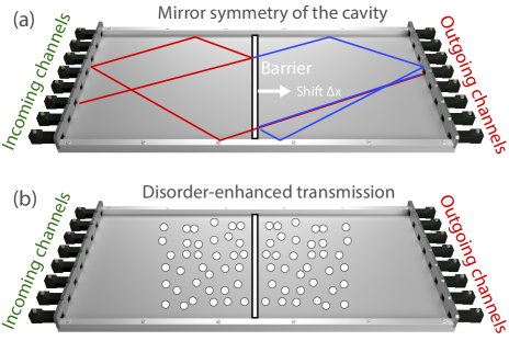
Our experimental setup is a multichannel cavity of length m, width m and height mm (see Fig. S1(a)). The cavity is effectively two-dimensional as a single vertically polarized mode can propagate. Spectra of the complete transmission matrix (TM) are measured between two arrays of antennas. These antennas are single waveguide channels fully coupled to the system between 11 and 17 GHz that are attached to the cavity at the left and right interfaces (see Fig.S1) Davy et al. (2021). The TM is built upon the field transmission coefficients between each incoming antenna and outgoing antenna . We stress that strong internal reflections at the interfaces of the cavity result from metallic boundary conditions at the spacing between the antennas. All openings of the cavity are controlled with transmitting or receiving antennas and the TM is therefore complete.
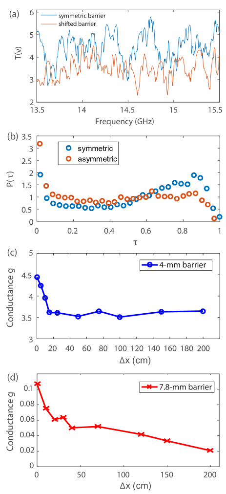
We first explore the impact of left-right mirror symmetry on the conductance with a single barrier which is a 4 mm height metallic rectangular bar. The barrier is first placed symmetrically to the left and right interfaces () and then shifted from the center by mm. The spectrum of the transmittance, which is the sum of the total transmsission over all the incident channels is seen to be larger in the symmetric configuration. The dimensionless conductance found from an averaging over the frequency range is given by for and for mm (see Fig. 2(a)).
The transmittance may also be expressed in terms of the transmission eigenvalues of , Imry and Landauer (1999). The distribution is found to be bimodal, as expected for multichannel cavities Baranger and Mello (1994); Jalabert et al. (1994); Rotter and Gigan (2017), with two peaks corresponding to closed channels () and open channels () (see Fig. 2(b)). This distribution highlights that such a sample can be either opaque or almost transparent to incoming radiations depending on the incident wavefront. Note that the peak for open channels is here found at instead of as a result of small dissipation within the sample Goetschy and Stone (2013); Davy et al. . As illustrated with numerical simulations of random asymmetrical media in Supplementary Material, small losses within the sample indeed leads to a shift of the second characteristic peak towards smaller transmission but does not suppress it Yamilov et al. (2016). As the configuration becomes asymmetric (), the amplitude of this peak is further reduced leading to smaller values of .
The conductance shown in Fig. 2(c) decreases rapidly with increasing between and mm, and for mm, it reaches a plateau. This shift is of the order of mm at a frequency of GHz. We then increase the barrier’s reflectivity by using a metallic bar with height of mm. The barrier now almost fully fills the height of the system. The reduction of with is even more significant as it almost reaches an order of magnitude, from for to for mm (see Fig. 2(d)).
The origin of the enhancement of in a symmetrical configuration can be understood from the schematic view of two scattering paths for a symmetric barrier given in Fig. S1, as shown in Ref. Whitney et al. (2009a). For an incident wave impinging on the barrier with an angle , the transmitted field to an outgoing channel can be split into two mirror scattering paths. The first path is successively reflected by the barrier (coefficient ), reflected at the left interface in the spacing between two antennas and finally transmitted through the barrier (coefficient ) before being absorbed at the right receiving channel (see red path on Fig. S1(a)). Its contribution for a path length is ( is the wave number). The second scattering path of length is first transmitted through the barrier and then follows a path which is the mirror of at the right side of the cavity, . For a mirror symmetry giving , the intensity is significantly enhanced relative to its average found when and are independent random variables.
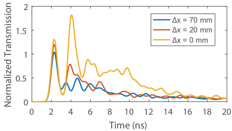
To illustrate the impact of constructive interference, we consider the time variation of transmitted field in Fig. (3). The field transmission coefficients in the time domain are obtained from the inverse Fourier transform of the elements for a Gaussian pulse of central frequency GHz and bandwidth MHz. We compare for , mm and mm. The magnitude of the first pulse found at ns weakly depends on as the ballistic wave through the cavity is barely impacted by the position of the barrier. However, the second pulse associated to the double scattering illustrated in Fig. S1(a) is nicely enhanced by the mirror-symmetry with a magnitude which even exceed the one of the direct pulse for . At late times, the pulses associated to multiple scattering between the barrier and the interfaces are mixed and therefore cannot be resolved temporally but for dominates the other curves until ns.
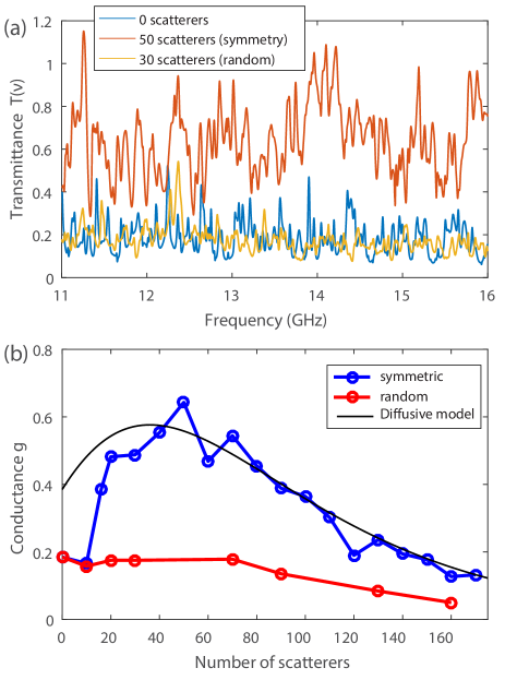
After testing the impact of the barrier alone, we show that the conductance can be further enhanced by introducing a diffusive medium with a symmetric arrangement. We place a collection of aluminum cylinders on both sides of the mm high barrier (see Fig. S1(b)). The transmittance is shown in Fig. 4(a) for , for two independent random configurations on both sides of the barrier, and for a random arrangement with a mirror symmetry. For a non-symmetric configuration, the system is slightly more opaque than for a barrier alone as the disorder strength has increased. However, a clear broadband enhancement is observed for symmetrically placed metallic scatterers. indeed increase with , reaches a maximum value of for and then decreases with as it is expected to vanish in the strong disorder limit (see Fig.4(b)). In contrast, in absence of mirror symmetry only decreases with as a result of the combined effect of disorder and the barrier.
The experimental results are now compared to a diffusive model proposed for disordered waveguides with open boundary conditions at left and right surfaces Chéron et al. (2020b). We do not expect that this model can accurately describe our experimental results for small , as it does not account for the strong internal reflections at both interfaces. For large , however, the main process is the diffusion within the scattering disorder. The key parameters are the barrier strength , with the conductance in absence of disorder, the normalized sample length , with the mean free path, and , with the ballistic absorption length. A scaling model including losses gives the following expression for the theoretical conductance :
| (1) |
Here, corresponds to the absorbing diffusive conductance in the absence of the barrier and . reflects the enhancement of the conductance due to mirror symmetry, , where is a parameter that has been found from a fit of with in numerical simulations.
In empty chaotic cavities the conductance is equal to . We therefore estimate that the conductance associated to the barrier in absence of internal reflections is giving . We then use that 1) scales linearly with , , and 2) the optimal conductance is found for so that with, in the absence of absorption, . Our experimental results shown in Fig. 4(b) present a maximum of for approximatively 50 scatterers but strong fluctuations on the data are observed around this optimal value. Moreover, should be its value in the absence of absorption and is therefore larger than . We estimate here that is reasonable value that provides a good agreement with the data. The last parameter is finally obtained from the best fit of the tail of as . The theoretical curve is in a good agreement with measurements in Fig. 4(b) for . We stress that the enhancement of the conductance is even stronger in our system relative to open random waveguides as the transmission for a barrier alone is reduced by a factor due to strong internal reflections at the metallic boundaries of the cavity.
In conclusion, we have provided a clear experimental observation of the impact of interference effects due to mirror symmetry on the transmission through disordered multichannel cavities. For a barrier placed within a cavity with strong internal reflections at its interfaces, constructive interference yields a broadband enhancement of the fraction of open transmission eigenchannels and consequently of the conductance. A further increase of the conductance has been obtained by symmetrically placing scatterers around the barrier, with experimental results in good agreement with a theoretical model including losses. The sensitivity of these systems may also open up new perspectives to detect defects within complex structures.
I Supplementary Material
See supplemental material for numerical simulations of the distribution of transmission eigenvalues in random samples with absorption.
II Acknowledgments
This publication was supported by the European Union through the European Regional Development Fund (ERDF), by the French region of Brittany and Rennes Métropole through the CPER Project SOPHIE/STIC & Ondes. M. D. acknowledges the Institut Universitaire de France. C. F. acknowledges funding from the French ”Ministère de la Défense, Direction Générale de l’Armement”. E. C. acknowledges funding by the project HYPERMETA funded under the program Etoiles Montantes of the Region Pays de la Loire.
The data that support the findings of this study are available from the corresponding author upon reasonable request.
References
- Dorokhov (1984) O. N. Dorokhov, Solid State Commun. 51, 381 (1984).
- Imry (1986) Y. Imry, Europhys. Lett. 1, 249 (1986).
- Mello et al. (1988) P. A. Mello, P. Pereyra, and N. Kumar, Ann. Phys. (N.Y.) 181, 290 (1988).
- Beenakker (1997) C. W. J. Beenakker, Rev. Mod. Phys. 69, 731 (1997).
- Vellekoop and Mosk (2008) I. M. Vellekoop and A. P. Mosk, Phys. Rev. Lett. 101, 120601 (2008).
- Kim et al. (2012) M. Kim, Y. Choi, C. Yoon, W. Choi, J. Kim, Q.-H. Park, and W. Choi, Nature Photon. 6, 583 (2012).
- Goetschy and Stone (2013) A. Goetschy and A. â. Stone, Phys. Rev. Lett. 111, 063901 (2013).
- Gérardin et al. (2014) B. Gérardin, J. Laurent, A. Derode, C. Prada, and A. Aubry, Phys. Rev. Lett. 113, 173901 (2014).
- Sarma et al. (2016) R. Sarma, A. G. Yamilov, S. Petrenko, Y. Bromberg, and H. Cao, Phys. Rev. Lett. 117, 086803 (2016).
- Rotter and Gigan (2017) S. Rotter and S. Gigan, Rev. Mod. Phys. 89, 015005 (2017).
- Sarma et al. (2017) R. Sarma, A. Yamilov, and H. Cao, Appl. Phys. Lett. 110, 021103 (2017).
- Yılmaz et al. (2019) H. Yılmaz, C. W. Hsu, A. Yamilov, and H. Cao, Nature Photon. 13, 352 (2019).
- Yablonovitch (1993) E. Yablonovitch, J. Opt. Soc. Am. B 10, 283 (1993).
- Akkermans and Montambaux (2007) E. Akkermans and G. Montambaux, Mesoscopic physics of electrons and photons (Cambridge University Press, 2007).
- Lagendijk et al. (2009) A. Lagendijk, B. Tiggelen, and D. Wiersma, Phys. Today 62, 24 (2009).
- Leseur et al. (2016) O. Leseur, R. Pierrat, and R. Carminati, Optica 3, 763 (2016).
- Aubry et al. (2020) G. J. Aubry, L. S. Froufe-Pérez, U. Kuhl, O. Legrand, F. Scheffold, and F. Mortessagne, Phys. Rev. Lett. 125, 127402 (2020).
- Whitney et al. (2009a) R. S. Whitney, P. Marconcini, and M. Macucci, Phys. Rev. Lett. 102, 186802 (2009a).
- Whitney et al. (2009b) R. S. Whitney, H. Schomerus, and M. Kopp, Phys. Rev. E 80, 056209 (2009b).
- Albada and Lagendijk (1985) M. P. V. Albada and A. Lagendijk, Phys. Rev. Lett. 55, 2692 (1985).
- Karpiuk et al. (2012) T. Karpiuk, N. Cherroret, K. L. Lee, B. Grémaud, C. A. Müller, and C. Miniatura, Phys. Rev. Lett. 109, 190601 (2012).
- Chéron et al. (2019) É. Chéron, S. Félix, and V. Pagneux, Phys. Rev. Lett. 122, 125501 (2019).
- Chéron et al. (2020a) É. Chéron, S. Félix, and V. Pagneux, Phys. Rev. B 102, 134201 (2020a).
- Chéron et al. (2020b) É. Chéron, S. Félix, and V. Pagneux, Sci. Rep. 10, 16635 (2020b).
- Davy et al. (2021) M. Davy, M. Kühmayer, S. Gigan, and S. Rotter, Commun. Phys 4, 85 (2021).
- Imry and Landauer (1999) Y. Imry and R. Landauer, Rev. Mod. Phys. 71, S306 (1999).
- Baranger and Mello (1994) H. U. Baranger and P. A. Mello, Phys. Rev. Lett. 73, 142 (1994).
- Jalabert et al. (1994) R. A. Jalabert, J. L. Pichard, and C. W. J. Beenakker, Europhys. Lett. 27, 255 (1994).
- (29) M. Davy, M. Kühmayer, S. Rotter, and D. Savin, in preparation .
- Yamilov et al. (2016) A. Yamilov, S. Petrenko, R. Sarma, and H. Cao, Phys. Rev. B 93, 100201 (2016).
Supplemental Material for ’Experimental evidence of enhanced broadband transmission in disordered systems with mirror symmetry”
I Supplemental Material for ’Experimental evidence of enhanced broadband transmission in disordered systems with mirror symmetry’
In this Supplementary Material, we explore the impact of losses on the distribution of transmission eigenvalues in simulations of waves propagating through lossy random media. Our experimental results presented in Fig. 2b of the main text indeed show that the peak corresponding to open channels is shifted from expected theoretically in absence of absorption Baranger and Mello (1994); Jalabert et al. (1994); Goetschy and Stone (2013) to and we attribute this effect to the impact of inevitable losses. We consider a two-dimensional waveguide of width and length with reflective transverse boundaries. The boundary conditions are opened at the right and left surfaces.
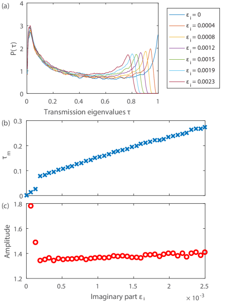
The wavelength is chosen so that the empty waveguide supports channels (). The Green’s functions between points at the input and output interfaces of a random waveguide are first obtained by solving the two-dimensional wave equation using the recursive Green’s function method Baranger and Mello (1994). The dielectric permittivity is a random asymmetrical function drawn from a rectangular distribution. We add a constant imaginary part representing absorption to . The elements of the transmission matrix between incoming modes and outgoing modes are then calculated by projecting the Green’s functions onto the modes of the empty waveguide. The transmission eigenvalues are found from a diagonalization of , with being the corresponding eigenvectors.
The distribution of transmission eigenvalues is found from an ensemble of 4000 random waveguides. The variance of is chosen so that the average transmission in the absence of absorption. In this case, is bimodal with two peaks at and corresponding to closed and open channels, respectively. However, the second characteristic peak shifts towards smaller transmission as absorption within the samples increases (see Fig. S1(a)), in agreement with our experimental result. The transmission corresponding to this peak increases monotonically with as seen in Fig. S1(b) with an amplitude first rapidly decreasing with absorption strength and then saturating (see Fig. S1(c)).
Even though the geometry of the cavity considered experimentally is different from the case of random waveguides since the empty cavity features strong internal reflections at left and right interfaces instead of internal disorder, these simulations demonstrate that small internal losses do not suppress the second peak on the distribution of transmission eigenvalues but rather leads to a shift of this peak.
References
- (1)
- Baranger and Mello (1994) H. U. Baranger and P. A. Mello, Phys. Rev. Lett. 73, 142 (1994).
- Jalabert et al. (1994) R. A. Jalabert, J. L. Pichard, and C. W. J. Beenakker, Europhys. Lett. 27, 255 (1994).
- Goetschy and Stone (2013) A. Goetschy and A. â. Stone, Phys. Rev. Lett. 111, 063901 (2013).