Abstract
We investigate experimentally and analytically the coalescence of reflectionless (RL) states in symmetric complex wave-scattering systems. We observe RL-exceptional points (EPs), first, with a conventional Fabry-Perot system for which the scattering strength within the system is tuned symmetrically, and then with single- and multi-channel symmetric disordered systems. We identify that an EP of the parity-time (PT)-symmetric RL-operator is obtained when the spacing between central frequencies of two natural resonances of the system is equal to the decay rate into incoming and outgoing channels. Finally, we leverage the transfer functions associated with RL and RL-EPs states to implement first- and second-order analog differentiation.
Exceptional points (EP) are spectral singularities in non-Hermitian systems at which two or more eigenvalues and eigenstates coalesce [1, 2, 3, 4, 5]. EPs have mainly been explored for resonant states that are the poles of the scattering matrix and scattering states. In systems with losses only, finding an EP between two resonant modes requires that the mutual coupling between resonances satisfy a critical relation with their loss factors [6]. EPs are however more easily realizable in systems with PT-symmetry obtained by balancing gain and loss in symmetric regions [7, 6]. Many unconventional features of EPs have been demonstrated theoretically and experimentally such as the design of unidirectional invisibility [8, 9], asymmetric mode switching [10] or directional lasing [11], to cite a few (see Refs. [12, 6] for reviews). These spectral singularities are also interesting for sensing applications since the energy (or frequency) splitting between degenerate eigenstates scales as the th root of the perturbation [13, 14].
Recently, a new kind of EPs associated with reflectionless (RL) scattering states rather than resonances has been investigated. RL states are eigenstates of a non-Hermitian operator based on the wave equation with incoming channels connected to a scattering system modeled as gain and outgoing channels modeled as losses [15, 16, 17]. The eigenvalues of are distinct from the resonance spectra related to the poles of the scattering matrix . When an eigenvalue is tuned to the real axis, the corresponding RL-state enable reflectionless coupling of incoming channels. The excitation of multi-channel RL-states in disordered matter requires non-trivial wavefront shaping [18].
A special case of RL-EPs found for purely incoming boundary conditions is the coalescence on the real axis of two zeros of the complete scattering matrix known as a perfectly absorbing EP [19, 20, 21]. The phenomenon of coherent perfect absorption (CPA) occurs when absorption within a scattering medium balances the excitation rate of incoming channels [22, 23, 24, 25]. CPA is the time-reverse of lasing at threshold [26, 27] and a generalization of the critical coupling condition [28, 24]. CPA has been implemented in a wide range of regular scattering systems [29], as well as in disordered matter [30, 31, 32, 33, 34, 35]. The latter has been achieved in particular through purposeful perturbations of the scattering system, which can include additional constraints, such as on frequency or CPA wavefront [30, 32, 33, 34]. When two CPA-states coalesce, the broadened lineshape of the absorption spectrum indicates the existence of perfectly absorbing EPs [19, 20, 21].
In flux-conserving systems, zero reflection and therefore perfect transmission of an incoming wavefront occurs when the decay rates into incoming and outgoing channels are equal. The probability of finding RL scattering modes is naturally enhanced in scattering systems with mirror-symmetry for which the RL-operator is PT-symmetric and RL-eigenvalues feature an exciting property. An RL-eigenvalue remains on the real axis under continuous perturbation of the system until it coalesces with a second one at an EP before splitting into a complex-conjugate pair [15, 19, 17]. The spectral broadening of the transmission peak corresponding to RL-EPs has been observed in multimirror cavities [36, 37, 38] and in numerical simulations of quantum dots [39] and atomic wires [40], even though not interpreted as an EP. However, a clear experimental demonstration of RL-EPs in disordered systems and an analysis of RL-states in term of natural resonances has to date not been reported.
In this article, we observe the existence of RL-EPs in symmetric regular and disordered systems that are tuned toward this scattering anomaly by inserting a symmetric defect. We first start with a multimirror Fabry-Perot cavity for which the reflectivity at the center is progressively increased. Our harmonic analysis reveals that an RL-EP is obtained when the spacing between the central frequencies of two quasi-normal modes (QNMs) is equal to their linewidth. Our experimental results in the microwave range are in excellent agreement with a two-level model. We then demonstrate RL-EPs in disordered single- and multi-channel waveguides. Finally, we show that designing systems operating at an RL-EP is relevant to analog computations of derivatives.
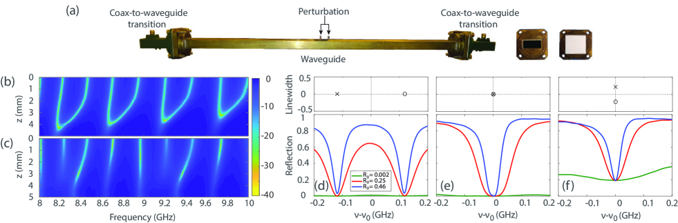
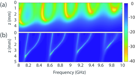
We measure spectra of the reflection coefficient and the transmission coefficient through a single-mode rectangular waveguide (length mm, width mm and height mm) with two coax-to-waveguide transitions attached to the openings (see Fig. 1(a)). A dielectric alumina slab of reflectivity (see SM) is positioned between each transition and the waveguide to increase the internal reflection at the interfaces. A perturbation is introduced symmetrically with respect to the center of the waveguide by inserting two aluminium rods (diameter mm) through two holes drilled into the top plate and spaced by mm. The penetration depth varies from 0 to mm in steps of mm (). This system is therefore equivalent to a multi-mirror Fabry-Perot interferometer with tunable reflectivity at the center.
A colormap of the reflection is shown in Fig. 1(b) on a log-scale. In absence of the perturbation (), the frequencies corresponding to extremely small reflection (bright area) are regularly spaced as expected for a Fabry-Perot interferometer. As the penetration depth increases, the RL-frequencies move closer until they coalesce for a critical perturbation () to form RL-EPs. The two peaks on the spectrum of found in the underperturbed regime () transform into a single broadband one at with a flattened quartic line shape which is characteristic of EPs [19, 20, 41, 21]. Once two RL-eigenvalues have collapsed, they leave the real axis as complex-conjugate pairs. In the overperturbed regime , the minimum of increases with as the imaginary part of RL-eigenvalues moves away from the real axis. In contrast, for an asymmetrical perturbation of the Fabry-Perot cavity (a single rod inserted at ), the zero-reflection frequencies do not collapse but move independently in the complex plane (see Fig. 1(c)).
The same procedure is then repeated for samples with zero and two alumina slabs at each interface, yielding and . For the smallest , the reflectivity is solely due to the small impedance mismatch between the transitions and the waveguide. In each case, a symmetric perturbation leads to the formation of RL-EPs. The linewidth of resonances decreases with increasing and the spectral dips corresponding to RL-states narrow as seen in Fig. 1(d-f).
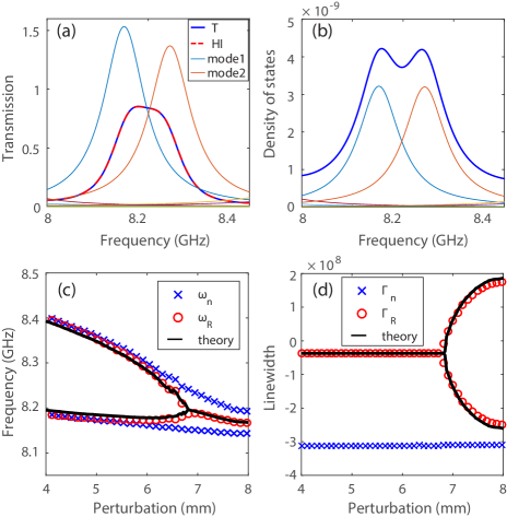
We now analyze RL-eigenvalues found by tracking the local minima of in terms of natural resonances of the medium. The QNMs are solutions of the wave equation with purely outgoing boundary conditions (i.e. for both left and right channels). The eigenstates are associated with complex frequencies with central frequency and linewidth . We extract the set of complex frequencies from a modal analysis of transmission spectra between 7 and 11 GHz using the harmonic inversion method [42, 2] (see SM). In absence of the perturbation, the central frequencies almost coincide with RL-frequencies. However, for , two overlapping resonances mainly contribute to the flattened transmission peak as seen in Fig. 2(a). Two peaks are observed on the spectrum of the density of states (DOS) in Fig. 2(b) with a spacing between central frequencies approximately given by the linewidths. Even for the highest penetration depth of the rods, the resonances do not coalesce.
We now derive analytical expressions of and RL-eigenvalues using a two-level model. The effective Hamiltonian of the open system is expressed in the basis of two successive modes of a closed one-dimensional waveguide, , with being a diagonal matrix with elements and . The left and right vectors and account for the coupling of the closed system to the channels and are real for systems with time-reversal symmetry. The scattering matrix writes , where . For an empty one-dimensional cavity of length , the th eigenfunction of the closed systems is . We consider here an even resonance () and an odd resonance (). The coupling vectors are related to the derivative of at and . is therefore symmetric, and is anti-symmetric . The coupling rate of each channel to the cavity depends on the reflectivity at the interfaces of the waveguide. The effective Hamiltonian is therefore a diagonal matrix with eigenvalues (see SM).
Inserting a rod in the middle of the waveguide leads to a local change of the permittivity. For a small penetration depth, the frequency shift of the two resonances can be calculated using standard perturbation theory. At first order, the shift is [44, 45]. For an even resonance, the field cancels at the center of the waveguide and . For odd resonances, and the central frequency shifts towards smaller values. As the penetration depth increases, resonances come together in pairs with central frequencies and spacings that are functions of , and .
RL-modes are eigenvalues of the PT-symmetric operator , where an effective gain is associated to incoming channels at the left interface. The coupling of the channels now results in anti-diagonal terms :
| (1) |
The RL-eigenvalues are then found from a diagonalization of :
| (2) |
Uniform absorption within the waveguide is incorporated by adding an imaginary part to complex frequencies. We estimate from the modal analysis that MHz (see SM).
When the coupling of channels is small compared to the spacing between resonances, , RL-eigenvalues are real and coincide with the central frequencies of resonances . However, the spacing between RL-eigenvalues decreases more rapidly than as the perturbation strength is symmetrically tuned. A reflectionless EP is found when losses through channels are equal to the spacing between the two resonances, . For larger perturbations, the two RL-eigenvalues become a complex-conjugate pair. Assuming that scales linearly with the penetration depth near the EP, (see SM), gives a splitting between RL-eigenvalues for near the EP which is characteristic of the square-root detuning behavior of EPs under small perturbations. The same splitting is found on imaginary parts of for .
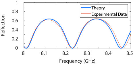
The experimental results in Fig. 2(c) for are in excellent agreement with the prediction of Eq. (2) in which we inject the values of , and extracted from the modal analysis. This agreement also highlights the effectiveness of the two-level model. For , the imaginary part of is equal to the absorption decay rate . For , we fit using the following analytical expression for the reflection coefficient (see SM for derivation):
| (3) |
and obtain an excellent agreement for in Fig. 2(d).
A signature of an EP is the flattening of close to [20, 21]. Eq. (S9) demonstrates that scales as at an EP and therefore features a quartic line shape. This is confirmed in Fig. 1(e) in reflection and Fig. 2(a) in transmission. We emphasize that decreases with increasing internal reflection so that the line shape is narrower for the sample with two dielectric slabs.
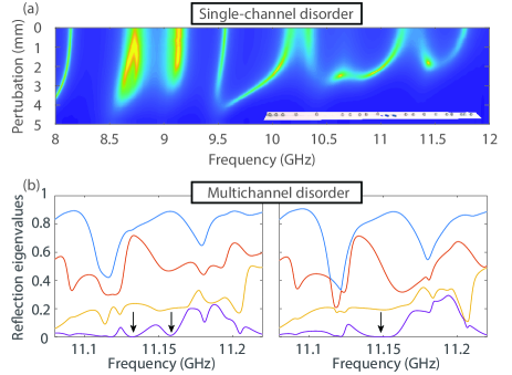
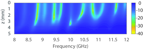
RL-EPs are not restricted to regular systems but exist in any complex multiple-scattering system. We now add a symmetric disorder made of 28 metallic spheres of diameter 5 mm within the empty waveguide (see Fig. 3(a)). The spacing between two spheres on the left side is drawn from a uniform random distribution and we replicate this disorder with a mirror symmetry on the right side. The spectrum still presents clear dips corresponding to RL-states but the spacing between two dips is now random. As the perturbation is symmetrically inserted, pairs of these dips collapse to give rise to RL-EPs. is also a random variable which reflects the random field distribution within the waveguide. In contrast to the Fabry-Perot cavity case, however, not all RL-eigenvalues are on the real axis for . An interesting case is the variation of RL-states around 8.73 GHz. Two eigenvalues first split at an EP for mm, move away along the real axis and then come back together to form a second EP for mm.
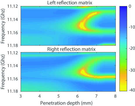
We also realize an RL-EP in a symmetric multichannel systems. Two arrays of transitions operating between 11 and 16 GHz are attached to an effectively two-dimensional rectangular cavity with metallic boundary conditions of length m, width m and height mm (see Refs. [46, 47] and SM for details). Spectra of the reflection matrices are measured both at the left and right interfaces of the cavity. The cavity is made disordered with 6 aluminum rods symmetrically placed on each side of the cavity. By tuning the penetration depth of two rods in the same way as for the single channel case, we identify an RL-EP on the last eigenvalue of at 11.15 GHz. The two zeros of coalesce at the RL-EP with a characteristic quartic line shape (see Fig. 3(b) and SM for the colorscale representation). We have verified that the same RL-EP is found on the reflection matrix at the other side of the cavity.
The incident wavefront corresponding with an RL-state is non-trivial in complex scattering systems and can be given by the eigenvector of with the smallest (near-zero) eigenvalue. When the spacing between two zeros is large, the corresponding eigenvectors are independent wavefronts. The degree of correlation between eigenvectors is equal to 0.55 for GHz. As we approach an RL-EP, the eigenvectors become strongly correlated with as the two RL-states coalesce. A single eigenvalue with a flattened shape is close to zero and no decrease is observed on . Note that the case of diabolical point with non-degenerate states [4] would be dramatically different. The orthogonality of the two states within the sample would lead to two reflection eigenvalues and being simultaneously close to zero with independent eigenvectors.
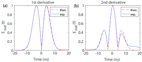
Finally, we note that the transfer functions associated with an RL state and an RL-EP state in reflection coincides with those of a first- and second-order differentiator, respectively. Wave-based signal processing holds the promise of being fast and energy-efficient. Implementations of higher-order derivatives have been proposed mainly in carefully engineered static optical fiber systems [48, 49, 50, 51, 52]. Recently, Ref. [41] proposed to leverage the unprecedented flexibility of complex scattering systems tuned to CPA in order to perform meta-programmable analog differentiation and implemented higher-order differentiation by cascading two systems tuned to CPA in order to emulate the transfer function of a CPA-EP. Here, by controlling the depth of the perturber penetration, we can tune our system to either an RL or RL-EP state. Thereby, we implement the second-order differentiator transfer function without using any non-linear components. For the prototypical example of a Gaussian input pulse, we calculate the envelopes of the output signal based on the measured transfer function for these two states. The results are displayed in Fig. 4 and in agreement with the analytically expected derivative. We attribute the imperfections to the fact that absorption prevents our RL-EP from lying directly on the real axis.
In conclusion, we have observed the coalescence of RL-states into EPs in regular and disordered single- and multi-channel scattering systems. We have shown that an RL-EP in a symmetric medium requires that the spacing between two resonances is perfectly balanced by the coupling rate of symmetric and anti-symmetric modes. An interesting extension of our work would consist in observing EPs related to transmissionless states [53]. These states can be found in two and three-dimensional scattering systems which theoretically provide the same behavior (broadened lineshape of the transmission spectrum and enhanced sensitivity of the zeros under perturbation of the system).
I Acknowledgments
This publication was supported by the European Union through the European Regional Development Fund (ERDF), by the French region of Brittany and Rennes Métropole through the CPER Project SOPHIE/STIC & Ondes. M. D. acknowledges the Institut Universitaire de France. C. F. acknowledges funding from the French “Ministère de la Défense, Direction Générale de l’Armement”.
II Data availability
The data that support the plots within this paper and other findings of this study are available from the corresponding authors on reasonable request.
References
- Heiss [2000] W. Heiss, Phys. Rev. E 61, 929 (2000).
- Berry [2004] M. V. Berry, Czechoslov. J. Phys. 54, 1039 (2004).
- Rotter [2009] I. Rotter, J. Phys. A 42, 153001 (2009).
- Moiseyev [2011] N. Moiseyev, Non-Hermitian quantum mechanics (Cambridge University Press, 2011).
- Cao and Wiersig [2015] H. Cao and J. Wiersig, Rev. Mod. Phys. 87, 61 (2015).
- Miri and Alù [2019] M.-A. Miri and A. Alu, Science 363, eaar7709 (2019).
- Özdemir et al. [2019] Å. K. Özdemir, S. Rotter, F. Nori, and L. Yang, Nat. Mater. 18, 783 (2019).
- Lin et al. [2011] Z. Lin, H. Ramezani, T. Eichelkraut, T. Kottos, H. Cao, and D. N. Christodoulides, Phys. Rev. Lett. 106, 213901 (2011).
- Fleury et al. [2015] R. Fleury, D. Sounas, and A. Alù, Nat. Comm. 6, 5905 (2015).
- Doppler et al. [2016] J. Doppler, A. A. Mailybaev, J. Böhm, U. Kuhl, A. Girschik, F. Libisch, T. J. Milburn, P. Rabl, N. Moiseyev, and S. Rotter, Nature 537, 76 (2016).
- Peng et al. [2016] B. Peng, Å. K. Özdemir, M. Liertzer, W. Chen, J. Kramer, H. Yilmaz, J. Wiersig, S. Rotter, and L. Yang, Proc. Natl. Acad. Sci. 113, 6845 (2016).
- El-Ganainy et al. [2018] R. El-Ganainy, K. G. Makris, M. Khajavikhan, Z. H. Musslimani, S. Rotter, and D. N. Christodoulides, Nat. Phys. 14, 11 (2018).
- Chen et al. [2017] W. Chen, Å. Kaya Özdemir, G. Zhao, J. Wiersig, and L. Yang, Nature 548, 192 (2017).
- Hodaei et al. [2017] H. Hodaei, A. U. Hassan, S. Wittek, H. Garcia-Gracia, R. El-Ganainy, D. N. Christodoulides, and M. Khajavikhan, Nature 548, 187 (2017).
- Bonnet-Ben Dhia et al. [2018] A.-S. Bonnet-Ben Dhia, L. Chesnel, and V. Pagneux, Proc. R. Soc. A 474, 20180050 (2018).
- Sweeney et al. [2020] W. R. Sweeney, C. W. Hsu, and A. D. Stone, Phys. Rev. A 102, 063511 (2020).
- Stone et al. [2020] A. D. Stone, W. R. Sweeney, C. W. Hsu, K. Wisal, and Z. Wang, Nanophotonics 1 (2020).
- Pichler et al. [2019] K. Pichler, M. Kuhmayer, J. Böhm, A. Brandstatter, P. Ambichl, U. Kuhl, and S. Rotter, Nature 567, 351 (2019).
- Sweeney et al. [2019] W. R. Sweeney, C. W. Hsu, S. Rotter, and A. D. Stone, Phys. Rev. Lett. 122, 093901 (2019).
- Suwunnarat et al. [2021] S. Suwunnarat, Y. Tang, M. Reisner, F. Mortessagne, U. Kuhl, and T. Kottos, arXiv:2103.03668 (2021).
- Wang et al. [2021] C. Wang, W. R. Sweeney, A. D. Stone, and L. Yang, Science 373, 1261 (2021).
- Li et al. [2017] H. Li, S. Suwunnarat, R. Fleischmann, H. Schanz, and T. Kottos, Phys. Rev. Lett. 118, 044101 (2017).
- Fyodorov et al. [2017] Y. V. Fyodorov, S. Suwunnarat, and T. Kottos, J. Phys. A Math 50, 30LT01 (2017).
- Baranov et al. [2017] D. G. Baranov, A. Krasnok, T. Shegai, A. Alù, and Y. Chong, Nat. Rev. Mater. 2, 17064 (2017).
- Krasnok et al. [2019] A. Krasnok, D. Baranov, H. Li, M.-A. Miri, F. Monticone, and A. Alù, Adv. Opt. Photonics 11, 892 (2019).
- Chong et al. [2010] Y. D. Chong, L. Ge, H. Cao, and A. D. Stone, Phys. Rev. Lett. 105, 053901 (2010).
- Roger et al. [2015] T. Roger, S. Vezzoli, E. Bolduc, J. Valente, J. J. F. Heitz, J. Jeffers, C. Soci, J. Leach, C. Couteau, N. I. Zheludev, and D. Faccio, Nat. Commun. 6, 7031 (2015).
- Piper et al. [2014] J. R. Piper, V. Liu, and S. Fan, Appl. Phys. Lett. 104, 251110 (2014).
- Wan et al. [2011] W. Wan, Y. Chong, L. Ge, H. Noh, A. D. Stone, and H. Cao, Science 331, 889 (2011).
- F. Imani et al. [2020] M. F. Imani, D. R. Smith, and P. del Hougne, Adv. Funct. Mater. 30, 2005310 (2020).
- Chen et al. [2020] L. Chen, T. Kottos, and S. M. Anlage, Nat. Commun. 11, 1 (2020).
- Frazier et al. [2020] B. W. Frazier, T. M. Antonsen Jr, S. M. Anlage, and E. Ott, Phys. Rev. Research 2, 043422 (2020).
- del Hougne et al. [2021] P. del Hougne, K. B. Yeo, P. Besnier, and M. Davy, Laser Photonics Rev. 15, 2000471 (2021).
- Del Hougne et al. [2021] P. Del Hougne, K. B. Yeo, P. Besnier, and M. Davy, Phys. Rev. Lett. 126, 193903 (2021).
- Chen et al. [2021] L. Chen, S. M. Anlage, and Y. V. Fyodorov, Phys. Rev. E 103, L050203 (2021).
- Van de Stadt and Muller [1985] H. Van de Stadt and J. M. Muller, J. Opt. Soc. Am. A 2, 1363 (1985).
- Stone et al. [1990] J. Stone, L. Stulz, and A. Saleh, Electron. Lett. 26, 1073 (1990).
- Stephen et al. [2017] M. Stephen, M. Fahey, and I. Miller, Applied optics 56, 2636 (2017).
- Joe et al. [2000] Y. S. Joe, D. S. Ikeler, R. M. Cosby, A. M. Satanin, and C. Sub Kim, J. App. Phys. 88, 2704 (2000).
- Lee and Kim [2001] H.-W. Lee and C. Kim, Phys. Rev. B 63, 075306 (2001).
- Sol et al. [2021] J. Sol, D. R. Smith, and P. del Hougne, arXiv:2108.06178 (2021).
- Kuhl et al. [2008] U. Kuhl, R. Höhmann, J. Main, and H. J. Stöckmann, Phys. Rev. Lett. 100, 254101 (2008).
- Davy and Genack [2018] M. Davy and A. Z. Genack, Nat. Comm. 9, 4714 (2018).
- [44] M. Cotrufo, E. Verhagen, and A. Fiore, in Quantum Sensing and Nano Electronics and Photonics XIV, Vol. 10111 (International Society for Optics and Photonics) p. 1011128.
- Cogn’ee et al. [2019] K. G. Cognée, W. Yan, F. La China, D. Balestri, F. Intonti, M. Gurioli, A. F. Koenderink, and P. Lalanne, Optica 6, 269 (2019).
- Davy et al. [2015] M. Davy, Z. Shi, J. Park, C. Tian, and A. Z. Genack, Nat. Commun. 6 (2015).
- Davy et al. [2021] M. Davy, M. Kuhmayer, S. Gigan, and S. Rotter, Commun. Phys 4, 85 (2021).
- Ngo et al. [2004] N. Ngo, S. F. Yu, S. Tjin, and C. Kam, Opt. Commun. 230, 115 (2004).
- Hsue et al. [2004] C.-W. Hsue, L.-C. Tsai, and K.-L. Chen, IEEE Trans. Microw. Theory Tech. 52, 1443 (2004).
- Kulishov and Azaña [2005] M. Kulishov and J. Azaña, Opt. Lett. 30, 2700 (2005).
- Park et al. [2007] Y. Park, J. Azaña, and R. Slavík, Opt. Lett. 32, 710 (2007).
- Li et al. [2009] M. Li, D. Janner, J. Yao, and V. Pruneri, Opt. Express 17, 19798 (2009).
- Kang and Genack [2021] Y. Kang and A. Z. Genack, Phys. Rev. B 103, L100201 (2021).
Supplementary Material for ’Exceptional points of PT-symmetric reflectionless states in complex scattering systems”
I Experimental Setups
I.1 Multi-Mirror Fabry-Perot Interferometer
In Fig. 1(b,c) of the main text, we have presented a colormap of the reflection with respect to the frequency and the depth of the two rods inserted within the waveguide when a single dielectric alumina slab was placed between each coax-to-waveguide transition and the waveguide. The aim of this slab is to enhance the reflectivity at the interface and the Q-factor of the resonances. The collapse of RL states into RL-EPs however does not depend on this reflectivity and is a more general phenomenon. In Fig. S1, we show the same colormap for 0 and 2 dielectric slabs at each interface.
Remarkably, the system still acts as a Fabry-Perot interferometer even without the slabs with regularly spaced RL-frequencies in absence of the perturbation. The reflectivity is very small but non-vanishing as the leads (coax-to-waveguide transitions) are well but not perflectly matched to the waveguide. The reflection average over the frequency range and the Q-factor of the resonances are small leading to broad zeros in reflection. In contrast, for 2 dielectric slabs, the resonances with large Q-factors are peaked and the EPs are narrower. In both cases, As increases, RL-EPs can be oberseved as increases.
We estimate the reflectively at the interfaces provided by 0, 1 or 2 dielectric slabs by fitting the spectrum of the reflection for an empty waveguide with its theoretical formula for a Fabry-Perot cavity
| (S1) |
with quantifying the phase shift of the wave propagating from one Fabry-Perot mirror to the other. Here is the wave number and the distance between the mirrors. The spectrum of the reflection and its best fit for a single dielectric slab placed at each interface is shown in Fig. S2. We estimate that , and for 0, 1 and 2 slabs, respectively.
I.2 Disordered one-dimensional medium
As mentioned in the main text, RL-EPs can exist in any complex multiple-scattering systems. We add inside the waveguide a random single-channel disorder made of the same 28 metallic spheres as those presented in the main text. The reflection is shown in Fig. S3. Without perturbation (), the spectrum presents randomly spaced dips. In contrast to the Fig. 3(a), one can see less RL-EPs with the random disorder than the symmetric one. Indeed, with a symmetrical disorder, the RL-eigenvalues can leave the real axis only by coalescing with another RL-eigenvalue whereas with a random disorder, a RL-eigenvalue can randomly leave the real axis by itself.
II Theoretical analysis
In this section, we provide more details on the calculations using the effective two-level Hamiltonian approach. The effective Hamiltonian writes
| (S2) |
where the left and right vectors and account for the coupling of the channels to the closed system. In the basis of two modes of the closed waveguide, is a diagonal matrix with elements and . We have identified that the coupling vectors are symmetric, and anti-symmetric , respectively (see main text). is the coupling rate of the channels to the cavity and therefore on the reflectivity at the interfaces of the waveguide. This yields
| (S3) |
Its eigenvalues are then
| (S4) |
The scattering matrix can then be derived from the effective Hamiltonian using , where . The reflection coefficient at the left interface is especially given by . Using that
| (S5) |
we find
| (S6) |
This equation can then be simplified to
| (S7) |
which is Eq. (3) of the main text.
Simple calculations show that the expression of can also be factorized in terms of eigenfrequencies and RL-eigenvalues as
| (S8) |
As expected, vanishes when .
III Modal Analysis
III.1 Harmonic Inversion
To extract the resonances of the system, we perform a modal analysis between 7 and 11 GHz of the transmission coefficient. We seek to decompose as
| (S9) |
The coefficients are the modal transmission coefficients that are associated with each resonance. We use the Harmonic Inversion (HI) method applied to the inverse Fourier transform of in the time domain [1, 2]. An excellent agreement with experimental results is found with 19 modes.
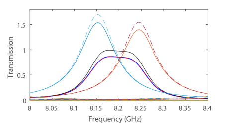
Uniform losses within the sample broaden the linewidth, , and reduces transmission through the sample. We now estimate the absorption rate at a RL-EP in the case of a perturbed Fabry-Perot interferometer with one dielectic slab placed at each interface. The maximum transmission found experimentally at the RL-EP is 0.865. We compensate the linewidth in the reconstructed spectrum of and find that the transmission reaches unity for MHz, as shown in Fig.S4.
We observe that a slight asymmetry on the flattened line shape of the transmission spectrum found experimentally at the EP. The strengths of the two modes contributing to the transmission are indeed not equal. Their maxima are and . We attribute this difference to the joint effects of a non-perfect symmetry of the system due to inevitable fabrication errors and a non-uniform absorption strength. Note that the modal strength exceeds unity as a consequence of the bi-orthogonality of quasi-normal modes in open systems [3]. In symmetric systems, is equal to the Petermann factor of the modes, which is a measure of the degree of complexness of the eigenfunctions [4]. For isolated resonances, but increases with the modal overlap between resonances. Here, two resonances are overlapping yielding .
III.2 Spacing between resonant frequencies
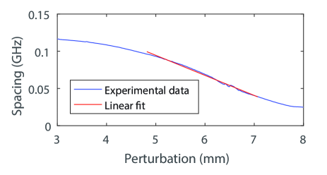
In Fig. S5, the spacing between two resonant frequencies is shown as a function of the penetration depth for a Fabry-Perot cavity with a a single alumina slab placed at each interface. Near the EP at mm, is seen to be well approximated with a linear function. Using that , we can write , where is a positive coefficient. The spacing between real RL-eigenvalues gives . In the vicinity of the EP, the square root behavior reflects the square-root sensitivity of EPs to an external perturbation of the system. The same is obtained for on the splitting of the imaginary parts of the two complex-conjugate RL-eigenvalues.
IV Multichannel cavity
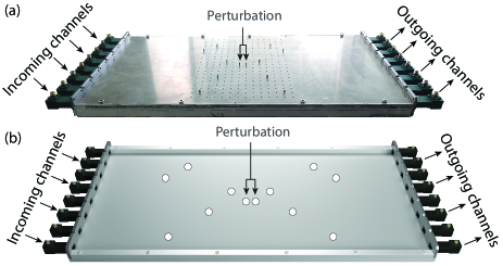
The reflection coefficient and the transmission coefficient are measured through a rectangular multi-channel cavity (length mm, width mm and height mm) between two arrays of single-channel. Note that transitions are observed at each side of the cavity on Fig. S6. However, only 4 of them are used to measure the reflection matrix. The others are not connected to the VNA. This open-circuit condition is similar to a metallic boundary conditions for the cavity.
An array of holes are drilled symmetrically with respect to the center on the top plate of the cavity with a spacing of mm between each hole (see Fig.S6(a)). Ten aluminium rods are inserted symmetrically through these holes thus creating a symmetric disorder inside the cavity (see Fig. S6(b)). As with the single mode waveguide presented in the main text, a perturbation is then introduced in the cavity by inserting symmetrically two aluminium rods spaced by mm near to the center. The penetration depth of these two rods is tuned to observe the RL-EPs.
Due to its large dimensions and inevitable fabrication errors, the cavity is not perfectly symmetric. However, we verify that the RL-EP presented in the main text is found on the both the left and right reflection matrices. In Fig. S7, we present the colorscale representation of the smallest reflection eigenvalues for both matrices. The multichannel RL-EP can be clearly observed on the two figures as expected.
References
- Mandelshtam and Taylor [1997] V. A. Mandelshtam and H. S. Taylor, J. Chem. Phys. 107, 6756 (1997).
- Davy and Genack [2018] M. Davy and A. Z. Genack, Nat. Comm. 9, 4714 (2018).
- Davy and Genack [2019] M. Davy and A. Z. Genack, Phys. Rev. Res. 1, 033026 (2019).
- Poli et al. [2010] C. Poli, O. Legrand, and F. Mortessagne, Phys. Rev. E 82, 055201(R) (2010).