Intelligent Reflecting Surfaces for Enhanced NOMA-based Visible Light Communications
Abstract
The emerging intelligent reflecting surface (IRS) technology introduces the potential of controlled light propagation in visible light communication (VLC) systems. This concept opens the door for new applications in which the channel itself can be altered to achieve specific key performance indicators. In this paper, for the first time in the open literature, we investigate the role that IRSs can play in enhancing the link reliability in VLC systems employing non-orthogonal multiple access (NOMA). We propose a framework for the joint optimisation of the NOMA and IRS parameters and show that it provides significant enhancements in link reliability. For example, the bit-error-rate of the NOMA user in the first decoding order is reduced to the order of using the proposed framework compared to an error floor of under fixed power allocation and fixed IRS reflection coefficients. The enhancement is even more pronounced when the VLC channel is subject to blockage and random device orientation.
Index Terms:
visible light communication (VLC), light fidelity (LiFi), intelligent reflecting surface (IRS), non-orthogonal multiple access (NOMA).I Introduction
The research and implementation of visible light communication (VLC) and light fidelity (LiFi) systems have gained significant interest in the last few years. While VLC systems support point-to-point transmissions based on the modulation of light-emitting diodes, LiFi refers to VLC-based networked solutions that offer diverse functionalities such as bidirectional connectivity, mobility support, and multi-user access [1, 2, 3]. In order to support ubiquitous multi-user connectivity, various multiple access techniques have been proposed for LiFi systems including orthogonal multiple access (OMA) and non-orthogonal multiple access (NOMA) [4, 5]. In OMA, different users are allocated orthogonal resources in either the frequency or time domain, while NOMA allows the multiplexed users to share the same bandwidth and time resource blocks using multiplexing in the power domain.
The application of power-domain NOMA to VLC was shown to provide promising spectral efficiency enhancements. In this context, power-domain NOMA employs superposition coding at the access point (AP) by assigning distinct power levels to the different users’ signals. The power allocation coefficients are determined based on the channel conditions such that users with more favorable channel gains are allocated lower power levels. Based on this, successive interference cancellation (SIC) can be performed at the user equipments to decode and subtract the signals with higher power levels first until the desired signal is extracted.
Adequate power allocation is essential for successful SIC. In particular, it is favorable to have disparate channel conditions for the users in order to allow more freedom in the power allocation coefficients. Nevertheless, this condition is not always met in VLC. This is due to the fact that the optical channel gain is not subject to small-scale fading, and therefore it is highly likely for multiple users to experience similar channel conditions, hindering the feasibility of NOMA [6]. This limitation might be overcome with the aid of the newly emerging concept of intelligent reflecting surfaces, which suggests that the environment itself can be programmed in order to enhance the communication performance.
While the concept of IRSs has been well-investigated in the context of radio frequency (RF) communications [7], the application of this emerging technology to VLC is still in its infancy. Metasurfaces and micro-electromechanical mirrors have primarily been proposed as possible solutions for light manipulation in VLC systems. An IRS is envisioned as an array of passive reflecting elements whose reflectivity can be dynamically adjusted by tuning the surface impedance through an electrical voltage stimulation. A detailed overview of the advantages and challenges related to the integration of IRSs in the context of VLC and LiFi systems is presented in [8]. The use of wall-mounted IRSs to focus the incident light beams towards optical receivers in indoor VLC systems was proposed in [9], in order to overcome line-of-sight (LoS) blockage. The energy efficiency maximisation of IRS-assisted VLC systems by jointly optimizing the time allocation, power control, and reflector phase shift for each user based on an iterative algorithm was investigated in [10]. On the other hand, [11] considered the optimisation of the IRS reflection coefficients with the objective of sum rate maximisation via a greedy algorithm. The secrecy capacity performance of IRS-assisted VLC systems was investigated in [12], where a swarm optimisation algorithm was implemented to optimise the orientation of the REs in order to maximise the achievable secrecy capacity.
In this paper, we investigate the potential performance enhancement that can be offered by integrating IRSs in NOMA-based VLC systems. While the users’ decoding order, and hence the power allocation, in conventional NOMA-based VLC can be decided based on the LoS channel gain, the case is more complicated in IRS-assisted systems. This is because the total channel gain perceived at the receiver can be manipulated by tuning the IRS. We propose a framework for the joint design of the NOMA decoding order, power allocation, and IRS reflection coefficients, with the aim of enhancing the bit-error-rate (BER) performance. We also show that this multi-dimensional optimisation problem is NP-hard and propose an adaptive-restart genetic algorithm (GA) in order to obtain a computationally efficient solution. To the best of our knowledge, this is the first paper that investigates NOMA-based IRS-assisted VLC systems. The rest of the paper is organised as follows. The system model is presented in Section II. Problem formulation and the proposed adaptive-restart GA are presented in Section III. Simulation results are shown in Section IV and the paper is concluded in Section V.
II System Model
In this section, we present the underlying assumptions for the channel and system model.
II-A Light Propagation Model
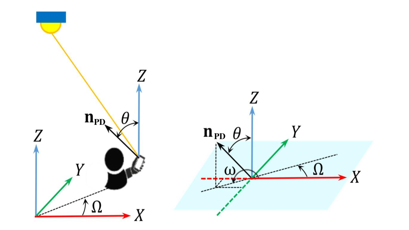
We focus on the downlink transmission of a VLC-based LiFi network with a single transmitting LED, UEs each employing a single photo-detector (PD), and an IRS consisting of REs. The link geometry is illustrated in Fig. 1. The LoS channel gain from the LED to the -th user’s PD is given by
| (1) |
for and otherwise, where
| (2) |
Each reflected path through an IRS RE is composed of two components, namely LED-to-RE path and RE-to-PD path. An approximate expression for the cascaded channel gain under the point source assumption was derived in [9]. Based on this, the cascaded channel gain through the -th RE is given by
| (3) |
for and otherwise, where
| (4) |

In (1) (2) (3), and (4), , , and denote the Euclidean distance from the LED to the -th user, the LED to the -th RE, and the -th RE to the -th user, respectively; is the physical area of the PD; and are the angles of irradiance with respect to the axis normal to the LED plane; and are the angles of incidence with respect to the axis normal to the receiver plane. From analytical geometry, the irradiance and incidence angles can be calculated as
| (5a) | |||
| (5b) | |||
| (5c) | |||
| (5d) |
where and are the normal vectors at the LED and the receiver planes, respectively, and the symbols and denote the inner product and the Euclidean norm operators, respectively. Furthermore, denotes the field-of-view (FoV) of the receiver; is the gain of the optical filter; is the gain of the optical concentrator given by
| (6) |
where stands for the refractive index; is the Lambertian order which is given by
| (7) |
where is the LED half-intensity angle [13].
II-B Random Orientation
The VLC link performance is influenced by the orientation of the mobile device [14]. The device orientation statistics have been derived through a set of experimental measurements for both sitting and walking activities in [15]. As shown in Fig. 2, the normal vector at the receiver plane, , can be expressed in terms of the polar angle, , and the azimuth angle, , in spherical coordinates, and can be written as
| (8) |
The azimuth angle denotes the angle between the positive direction of the axis and the projection of in the -plane.
Substituting (8) in (5b), (5d), (1), and (3), it can be inferred that for a fixed UE location, both the LoS and reflected channel gains depend on the polar angle . The experimental measurements reported in [15] suggest that the polar angle follows a Laplace distribution and that the probability density function (PDF) of the polar angle is given as
| (9) |
where and denote the mean and variance of , respectively.
II-C Link Blockage
Link blockage can significantly affect the user performance in VLC and LiFi systems. In this study, we consider the effect of dynamic blockage caused by other mobile users.
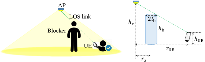
We follow the assumption in [16] and model a human body blocker as a cylinder wiof radius and height . as shown in Fig. 3. Assuming a Poisson point process (PPP) distribution with a density of for the blockers [17], the average probability of the link blockage is given as
| (10) |
where is the horizontal distance between the LED and the UE; with and being the heights of the UE and the LED, respectively. It is clear that the average link blockage probability depends on the geometry of the blockers as well as their density. While LoS blockage in traditional LiFi systems might result in complete link failure, the existence of reflected paths in IRS-assisted systems implies that such systems are more robust to link blockages.
II-D NOMA Transmission
NOMA employs superposition coding at the transmitter in order to multiplex users in the power domain. Hence, the received signal at user can be expressed as
| (11) |
where is the combined LoS and reflected channel gain of user ; is the reflection coefficient of the -th RE; is the power allocated to the -th user’s signal; denotes Gaussian noise with variance . In order to facilitate SIC at the receiver, the power allocated to the users is determined based on their channel gains. The perceived channel gain at user is governed by the combined LoS and reflected paths. Hence, the users’ ordering is dependent on the IRS reflection coefficients vector.
Multi-user interference at the -th user is canceled by employing SIC for higher power signals whereas the lower power users’ signals are treated as additive noise. Let denote the decoding order of the users such that denotes that user is in the -th decoding order, then the output signal of the -th SIC receiver can be written as
| (12) |
where
| (13) |
represents the interference. The pairwise error probability (PEP) of the -th user can be expressed as
| (14) | ||||
where . Hence, the conditional PEP can be written as
| (15) |
where represents the Gaussian Q-function.
III Problem formulation and proposed solution
This section introduces the problem formulation and the proposed adaptive-restart GA-based solution.
III-A Objective Function
Our aim is to minimise the maximum BER of the NOMA users, which is the error rate of the user with the first decoding order (this user exhibits the worst error performnce as it needs to decode its signal in the existence of high interference from all the other multiplexed signals). In order to reach our objective, we need to jointly optimise the users’ decoding order, power allocation, and IRS reflection coefficients. The optimisation problem can be formulated using the BER union bound defined as the weighted sum of all the PEP values, considering all possibilities of the transmitted symbols.
The objective function can be expressed as
| (16a) | |||
| (16b) | |||
| (16c) | |||
| (16d) |
where denotes the number of possible combinations of and , and the subscript denotes the user in the first decoding order. Also, is the users’ decoding order vector; is the ordered power allocation vector; is the reflection coefficients vector. Constraint (16b) ensures successful SIC, constraint (16c) is related to the tuning range of the REs, and constraint (16d) is related to the total transmit power constraint, where represents the power allocation coefficient for the -th user. Solving this optimisation problem requires a three-dimensional matching of , , and . Since the decisions on the optimal decoding order, power allocation, and IRS tuning are intertwined, (16a)-(16d) constitute a non-deterministic polynomial-time (NP)-hard problem that is non-trivial to solve [18]. In order to obtain the optimum design of , , and at each time slot, one could resort to evaluating all possible combinations through exhaustive search (ES). For the case of multiplexed users and REs, and assuming that the power allocation resolution is in the order of of the total LED power and that the resolution of the REs’ tuning is in the order of , the search space would have possible solutions. As a result, it is evident that using ES is computationally prohibitive for practical purposes (which is a result of NP hardness). Next, we explore how the GA can provide an effective tool for optimising the system design in a computationally efficient manner.
III-B Adaptive-Restart Genetic Algorithm
The GA is a powerful heuristic technique that mimics the evolution of natural organisms based on the idea of the "survival of the fittest". It has been proven to be an effective tool for obtaining computationally-efficient solutions for high-dimensional problems, including many in the field of wireless communications [19, 20].
The algorithm starts with an initial population of chromosomes, each of the form . The initial population represents a random subset of the possible solutions. In each iteration of the algorithm, the mutation operation is applied to the current population in order to generate slightly modified chromosomes for the next generation. Then, the crossover operation is performed to update the population by generating new offspring. Both mutation and crossover enable the exploration of new candidate solutions within the search space of candidate solutions. In each iteration, the fitness of the current population is evaluated and the fittest solutions are carried to the next iteration, i.e., the chromosomes whose fitness values are higher are kept whereas others are discarded during the selection phase. The fitness value of each candidate solution is evaluated according to the objective function in (16a).
| Description | Notation | Value |
|---|---|---|
| Number of NOMA users | ||
| FPA coefficient | ||
| Transmitter semi-angle | ||
| FoV of the PDs | ||
| Mean of PD polar angle | ||
| Variance of PD polar angle | ||
| Physical area of PD | ||
| Refractive index of PD lens | ||
| Gain of optical filter | ||
| Blockers’ height | m | |
| Blockers’ radius | m | |
| Blockers’ density (non-dense) | ||
| Blockers’ density (dense) |
Various modifications can be applied to each of the GA steps in order to enhance its performance and reduce the probability of getting stuck in a local optimum. We employ an adaptive restarting genetic algorithm which was proven to improve the global search capability compared to traditional GA [21]. Algorithm 1 illustrates the structure of the employed algorithm. The inner for loop is essentially the traditional GA with its five main steps, namely: chromosomes encoding, crossover, mutation, evaluation, and selection. The outer for loop restarts the GA with some "elite" quality chromosomes generated in the previous iteration. In the proposed framework, the GA works on a specific system setup, i.e., it inherently takes into account users’ channel state information (CSI), including locations, orientation of the devices, and link blockage probability. This renders it into a solid and powerful design method for jointly optimising the operation of NOMA and IRSs in dynamic LiFi setups.
IV Simulation Results
In this section, we present the simulation results considering an indoor scenario in a m3 room. Unless specified otherwise, the simulation parameters are shown in Table I. Our goal is to evaluate the NOMA BER performance in IRS-assisted VLC systems. Here, we only show the BER performance of the NOMA user in the first decoding order, since this user typically exhibits the worst error performance due to high interference.
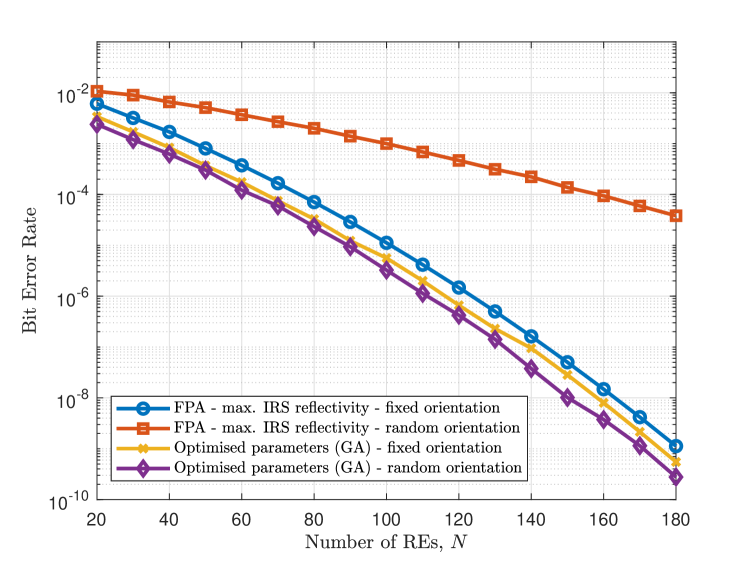
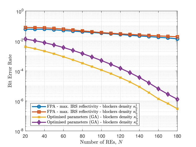
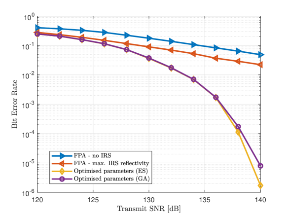
Fig. 4 shows the BER performance vs the transmit SNR for different scenarios, namely: 1) no IRS, 2) IRS with fixed maximum reflection coefficients, i.e., all IRS reflection coefficients are set to one, 3) the optimal decoding order, power allocation, and reflection coefficients based on ES, and 4) the proposed joint optimisation based on the adaptive-restart GA. For the first two scenarios, NOMA power allocation is performed based on the widely used fixed power allocation (FPA) strategy in which the power allocated to the -th ordered user is equal to , with being the FPA coefficient [22]. For the last two scenarios, we assume that the IRS is mounted on one of the walls and contains REs. It is shown in Fig. 4 that the BER enhancement offered by adding the IRS is limited in the case of fixed reflection coefficients. The proposed joint optimisation offers a significant BER reduction that allows for a reliable NOMA operation. For example, more than dB gain in transmit SNR is achieved for a BER of . Also, the BER is reduced to the order of for dB transmit SNR while it approaches an error floor for the case with no IRS or fixed IRS tuning. It can also be inferred that the proposed heuristic solution achieves near-optimal results when compared to the ES, which renders it an effective tool for solving the optimisation problem in question.
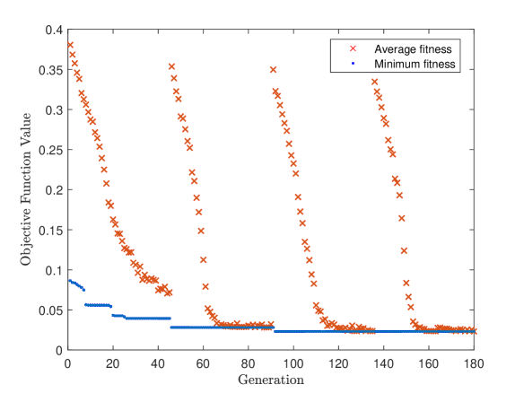
In order to gain insights into the convergence of the proposed adaptive-restart GA, we show its convergence vs the number of generations in Fig. 5. This figure shows the clear advantage of the adaptive-restart strategy compared to the basic GA. It can be inferred that the first iteration (which starts with a totally random population) does not converge to the best possible solution, and that the following iterations (that start with populations containing elite chromosomes) converge to better solutions.
Next, we investigate the role that IRSs play when the VLC link is subject to random device orientation and link blockage. Although these probabilistic factors are usually overlooked in the related literature, their effect can be detrimental to the link quality. Fig. 6(a) and Fig. 6(b) show the BER performance vs the number of REs when random device orientation (based on II-B) and link blockage probability (based on II-C) are considered, respectively. We can see that increasing the number of REs leads to a limited reduction in the BER when FPA and fixed REs tuning are employed. For the case where , the proposed joint optimisation results in a BER reduction from the order of to the order of when the link is subject to random orientation, and from a BER in the order of to when the LoS link is blocked.
V Conclusion
The integration of IRSs in VLC systems opens the door for unprecedented control of the channel conditions, which implies higher degrees of freedom in system design and optimisation. This paper proposed a framework for the joint optimisation of the decoding order, power allocation, and IRS reflection coefficients in NOMA-based VLC systems, based on an adaptive-restart GA. Our results show that the proposed method allows for higher link reliability in interference-limited NOMA systems, particularly when the links are subject to the adverse effects of blockage and random device orientation.
References
- [1] Harald Haas, Elham Sarbazi, Hanaa Marshoud, and John Fakidis. Chapter 11 - visible-light communications and light fidelity. In Alan E. Willner, editor, Optical Fiber Telecommunications VII, pages 443–493. Academic Press, 2020.
- [2] Harald Haas et al. Introduction to indoor networking concepts and challenges in LiFi. IEEE/OSA J. Opt. Commun. Netw., 12(2):A190–A203, 2020.
- [3] Ahmet Burak Ozyurt and Wasiu O. Popoola. Mobility management in multi-tier lifi networks. IEEE/OSA J. Opt. Commun. Netw., 13(9):204–213, 2021.
- [4] Jie Lian and Maïté Brandt-Pearce. Multiuser visible light communication systems using OFDMA. J. Lightw. Technol., 38(21):6015–6023, 2020.
- [5] Hanaa Abumarshoud, Hamada Alshaer, and Harald Haas. Dynamic multiple access configuration in intelligent LiFi attocellular access points. IEEE Access, 7:62126–62141, 2019.
- [6] H. Marshoud et al. Optical non-orthogonal multiple access for visible light communication. IEEE Wireless Commun., 25(2):82–88, 2018.
- [7] S. Gong et al. Toward smart wireless communications via intelligent reflecting surfaces: A contemporary survey. IEEE Commun. Surveys Tuts., 22(4):2283–2314, 2020.
- [8] Hanaa Abumarshoud et al. LiFi through reconfigurable intelligent surfaces: A new frontier for 6G? arXiv preprint arXiv:2104.02390v3, Apr. 2021.
- [9] A. M. Abdelhady et al. Visible light communications via intelligent reflecting surfaces: Metasurfaces vs mirror arrays. IEEE Open J. of the Commun. Soc., 2:1–20, Dec. 2021.
- [10] B. Cao et al. Reflecting the light: Energy efficient visible light communication with reconfigurable intelligent surface. in Proc. IEEE 92nd Vehicular Technology Conference (VTC2020-Fall), pages 1–5, Feb. 2021.
- [11] Shiyuan Sun, Fang Yang, and Jian Song. Sum rate maximization for intelligent reflecting surface-aided visible light communications. IEEE Commun. Lett., pages 1–1, 2021.
- [12] Lei Qian, Xuefen Chi, Linlin Zhao, and Anas Chaaban. Secure visible light communications via intelligent reflecting surfaces. arXiv preprint arXiv:2101.12390, Jan. 2021.
- [13] J. M. Kahn and J. R. Barry. Wireless infrared communications. Proceedings of the IEEE, 85(2):265–298, Feb. 1997.
- [14] Hanaa Abumarshoud, Mohammad Dehghani Soltani, Majid Safari, and Harald Haas. Realistic secrecy performance analysis for LiFi systems. IEEE Access, 9:120675–120688, 2021.
- [15] M. D. Soltani et al. Modeling the random orientation of mobile devices: Measurement, analysis and LiFi use case. IEEE Trans. Commun., 67(3):2157–2172, March 2019.
- [16] K. Dong, X. Liao, and S. Zhu. Link blockage analysis for indoor 60 GHz radio systems. Electronics Letters, 48(23):1506–1508, Nov. 2012.
- [17] Cheng Chen et al. Physical layer performance evaluation of wireless infrared-based LiFi uplink. arXiv preprint arXiv:1904.13163, 2019.
- [18] Jingjing others Cui. Optimal user scheduling and power allocation for millimeter wave NOMA systems. IEEE Trans. Wireless Commun., 17(3):1502–1517, 2018.
- [19] M. Selim Demir and Murat Uysal. A cross-layer design for dynamic resource management of VLC networks. IEEE Trans. Commun., 69(3):1858–1867, 2021.
- [20] Jun Wang et al. Joint beamforming and reconfigurable intelligent surface design for two-way relay networks. IEEE Trans. Commun., 69(8):5620–5633, 2021.
- [21] Farzad Ghannadian, Cecil Alford, and Ron Shonkwiler. Application of random restart to genetic algorithms. Information Sciences, 95(1):81–102, 1996.
- [22] Liang Yin, Wasiu O. Popoola, Xiping Wu, and Harald Haas. Performance evaluation of non-orthogonal multiple access in visible light communication. IEEE Trans. Commun., 64(12):5162–5175, 2016.