Non-Binary Polar Coded System for the Two-User Multiple-Access Channel
Abstract
This paper presents non-binary polar codes for the two-user multiple-access channel (MAC). The bit error rate (BER) performances of the non-binary polar codes with different kernel factors have been investigated in detail to select a proper parameter from for the generator matrix. Furthermore, the successive cancellation decoding for the non-binary polar codes in the two-user MAC is introduced in detail. Simulation results show that the choice of the kernel factors has a significant impact on the block error rate (BLER) performance; moreover, the non-binary polar codes provide a better BLER performance than their binary counterpart in the two-user MAC.
Index Terms:
Non-binary polar codes, two-user multiple-access channel, kernel selection, successive cancellation (SC) decoding.I Introduction
Polar codes have attracted widespread attention since they can achieve the Shannon limit [1], and much research has been done for polar codes in many aspects. Since 2012, polar codes have been considered for the multiple-access channel (MAC) [2]-[5]. Authors in [2] present a joint polarization for the two-user MAC, which results in five possible transmission models that achieve the dominant face of the capacity region. [3] extends the two-user case to the -user case, , and deduces the extremal points of the reachable rate region. However, the proposed joint polarization can only reach some of the capacity region instead of all. Paper [4] proposes compound polar codes for the two-user MAC, which can achieve the whole uniform rate region by changing the decoding order of the joint successive cancellation decoder. In [5], the authors utilize the generalized chain rule to construct polar codes for two-user MACs, achieving all the capacity region.
Moreover, the non-binary (NB) polar codes are also an appealing research field because of their flexible structure [6]-[10]. In [6], the authors exploit the randomized construction to polarize the arbitrary input discrete memoryless channel with the binary kernel. In [7], the authors present a non-binary kernel form that can be polarized if the input size is the power of a prime and the kernel’s parameter is the primitive element of the Galois Field . A polarized mapping scheme is discussed in [8], which is suited to both the sources and channels. It has been pointed out that multilevel polarization arises when the input size is the power of two [9]. Then non-binary kernels are considered in [10] to construct a system for polarized transmission, resulting in a better BLER performance than binary polar codes.
Some literature works have been done on non-binary polar codes for the MAC due to their appealing features. [11] constructs polar codes using the group structure when the MAC input is arbitrary, achieving the symmetric sum capacity except for some points. In [12], the authors present polarization theorems for arbitrary classical-quantum channels with Arikan style transformation, which can be used to construct polar codes for arbitrary classical-quantum MACs with relatively low complexity of encoding and decoding. A channel upgradation polar construction is generalized to the non-binary input MAC case to choose the polarization channel for data transmission [13][14].
The prior works mainly focus on the binary codes and the achievability of the rate region in theory. Based on the generalized chain rule proposed by [5], this paper presents a non-binary polar coded system for the two-user MAC, which mainly exploits the flexible design of the non-binary kernel and the successive cancellation (SC) decoding implementation.
The structure of this paper is arranged as follows. Section II presents the system model of the proposed scheme. A successive cancellation decoding algorithm of non-binary polar codes in the two-user MAC is presented in Section III. In Section IV, the selection of the kernel factors is discussed in detail. The simulation results of the proposed system are shown in Section V, followed by concluding remarks in Section VI.
II SYSTEM MODEL
We define , and as the binary, natural, and real field, respectively. The Galois field is denoted by , where and . Considering the element set in as , where is the primitive element of . We follow the notations defined in [1], denoting random variables and the corresponding samples by upper and lower case letters, respectively. Besides, stands for a vector , and denotes the subvector for . Let represent the Gaussian distribution with the mean and the variance .
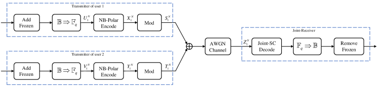
The system model is shown in Fig. 1. At the transmitter, the frozen bits are added to each user’s uncoded information while maintaining the sum rate for the whole system. Then every bits are converted to a non-binary symbol of serially. Denote as the code length of each block in the non-binary symbol form. The non-binary symbol blocks of users 1 and 2 are respectively defined by and , where , , and , , . Define as the kernel matrix, given by
| (1) |
Denote and as the kernel factor for users 1 and 2, respectively. The generator matrix of polar codes is defined by , where denote the -th Kronecker power of and is the reverse-shuffle. Note that the operations of addition and multiplication are both based on .
Let and denote the encoded polar codewords of users 1 and 2, given by
| (2) |
with , , and . The encoded polar codewords are then converted to bits. By using BPSK modulation, the modulated signals are and for users 1 and 2, respectively. Two users’ modulated signals are then transmitted to the multiple-access channel, and the received signals is given by
| (3) |
where , , and . The noise component satisfies .
At the receiver, the successive cancellation decoding is used to recover and , denoted by and . After converting and to bits and removing the frozen bits, the information bits of two users are obtained. By now, the description of the system framework is accomplished. Some definitions for the channel analysis of this system are given next.
Let be a two-user multiple-access channel. Symbol pair can be viewed as the input of , and denotes the corresponding transition probability. Set as independent uses of . Let and denote the input of from user 1 and user 2, while is the output of , then .
Like the case in [5], define the combined channel by
| (4) |
Since there is no mutual information loss during the polar transform, thus
| (5) |
To construct a polarization channel, is expanded as
| (6) |
where is the permutation of that preserves the monotone order of both and . Let indicate the relative order of . When , ; otherwise, .
The coordinate channels that correspond to (6) are defined as
| (7) | ||||
where and stand for the -th symbol of user 1 and the -th symbol of user 2, , . The coordinate channel transition probability is used in the decoding process as described in the next section.
III A JOINT SC DECODING ALGORITHM
In this section, a joint SC decoding is presented for the NB-polar codes in the two-user MAC. Since the generator matrix is determined by the row vector in , thus is used to describe the decoding process, ignoring operation that has no impact on the performance.
To calculate , we define the split MAC channel by
| (8) |
When considering the decoding order, the single user transition probability is derived as
| (9) | ||||
| (10) | ||||
The transition probability of the split MAC channel can be calculated recursively due to the recursive structure. For simplicity, here we use the notations similar to [5]. Let and , and define and , where the subscripts and denote the subvector with odd and even indices that are similar to and , respectively. Define
| (11) | ||||
Then the recursive equations are given by
| (12) | ||||
| (13) | ||||
| (14) | ||||
| (15) |
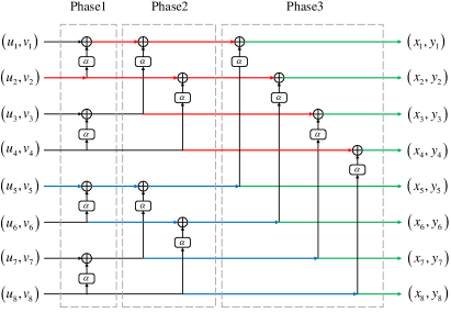
According to (12)-(15), the recursive transform implies a decoding path for each split channel. For example, the decoding path of is shown in Fig. 2, where red lines, blue lines, and green lines represent the decoding path for user 1, user 2, and both two users, respectively. Assuming that the phase index increases from the input side to the output side in the polar encoder, . In each phase, two users’ decoding paths are combined to calculate the corresponding probabilities.
When we decode symbol , , all the known decisions are viewed as auxiliary symbols, similarly to the symbol . Since the decoding process of and are reciprocity, we use the decoding process of with the auxiliary information for the analysis in the following.

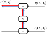
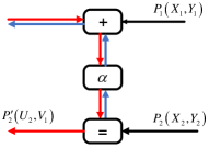
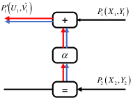
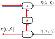
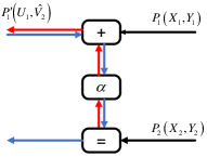
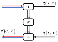
The transition probability transform corresponding to the decoding path of each phase is based on the combined basic structure, as shown in Fig. 3. The calculation of probability is divided into two categories: calculation and calculation, which correspond to decode and of the combined basic structure, respectively. According to (12)-(15), considering the number of auxiliary symbols, there are six types of calculations, denoted by , , and , , , respectively, as shown in Fig. 4. The subscript represents the number of the available auxiliary symbols of . Based on the combined basic structure and calculations, the decoding process of each phase is similar to the single-user case.
A complete binary tree of depth is defined first to indicate the SC decoding process [15]. Given a node , define its location of the decoding tree by the vector , representing the -th node of the -th depth, . Let the node’s parent node, left and right child node be , , and , respectively.
There are four kinds of information stored in the -th node : the probability matrices , decision symbol vector , auxiliary symbol vector , and child nodes set . Let be the -th row in , and be the -th element in , where , .
For a two-user decoding algorithm, two decoding trees are defined as and , respectively. As stated in [5], for simplicity, is defined as our decoding order, where . The decoding order can be naturally divided into three stages: decode in stage I, decode in stage II, and decode in stage III. Next, we will give a detailed description of the decoding process, consisting of six steps.
Step 1: Initialize and for stage I.
The transition probability is initialized to the root node’s of , denoted as
| (16) |
where . is initialized with a set for the internal node, including and . For the leaf node, is initialized with an empty set .
Step 2: The decoding process for stage I.
Update in . The node passing routine and update operation are relayed on the cardinality of , denoted as , and there are three cases.
If , change to its left child node and remove from . Let and update as
| (17) |
If , change to its right child node and remove from . Update as
| (18) |
If , change to its parent node . There are two situations for this case. On one hand, when is an internal node, let denote the left child node of , update as
| (19) |
On the other hand, when is a leaf node, make a decision on and update as
| (20) |
This stage is terminated when has been decoded.
Step 3: Initialize for stage II.
Some of in is initialized to in . Let . For the leaf node, initialize as
| (21) |
Then for the non-leaf node, let , is updated from the leaf side to the root side recursively
| (22) |
Step 4: The decoding process for stage II.
This process is similar to step 2. The difference exists in update with .
If , update as
| (23) |
If , update as
| (24) |
where . We choose different calculation types to calculate (23) and (24) according to the value of and . This stage is terminated when is decoded successfully.
Step 5: Initialize for stage III.
Some of in is initialized to in . Set and execute the recursive update in step 3, then the initialization for is accomplished.
Step 6: The decoding process for stage III.
This process is similar to step 4, and this stage is terminated when is decoded successfully.
The algorithm is summarized in Algorithm 1, which yields operations, a slight increase in contrast with the complexity of its binary counterpart.
IV THEORETICAL ANALYSIS OF THE KERNEL
This section focuses on the effect of the kernel. Since the reliability is relatively low in stage I, the performance is mainly determined by the kernels of stages II and III. First, we consider in stage III since has no effect when all the auxiliary symbols are already known. Then we optimize in stage II, assuming is fixed.
IV-A The Kernel of Stage III
The probability transform of stage III is equivalent to that of the single-user basic structure, as shown in Fig. 3, where and are the input and output, respectively.
Set , the transition probability can be written as
| (25) |
where , . The coordinate channel transition probability of is
| (26) | ||||
Acccording to the maximum likelihood detection, the decoded is
| (27) |
Define , . Assuming is transmitted, the probability of a correct decision is given by
| (28) |
Assume the detection of is independent, (28) becomes
| (29) |
Let denote , the term in (29) can be organized as
| (30) |
where and correspond to and , respectively. Since , the left side of (30) is also a Gaussian variable , where
| (31) |
and the probability is calculated by integrating the probability density function (PDF) of . The average BER is calculated by going through all . Then we choose the kernel factor that can provide the best BER performance.
IV-B The Kernel of Stage II
Assuming that is fixed, then we select the optimal . Set and , the transition probability is
| (32) |
Define , by , the split channel transition probability of is given by
| (33) |
Define . Assuming is transmitted, the probability of a correct decision is
| (34) |
It is hard to derive the term in (34) directly. Thus (33) is simplified by omitting the relatively small items. Assuming is transmitted, and correspond to . Let denote . Define and , , besides
| (35) |
where and correspond to and , respectively. Then (33) is approximated by
| (36) |
The situation degraded to the single-user case, and the average BER is calculated by going through all and . Then the kernel factor that provides the best BER is chosen.
V SIMULATION RESULTS
In this section, Monte Carlo method is used to simulate the BLER performances of the proposed system. In this work, we take the as an example to do analysis, and the theoretical BERs of different kernels are shown in Figs. 5 and 6. According to Fig. 5, is the optimal choice for the single-user case in . Thus let be the kernel factor for user 1. According to Fig. 6, is the optimal choice in the two-user case when . Thus let be the kernel factor for user 2.
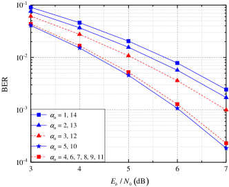
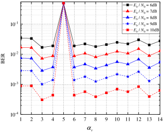
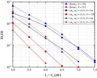
Fig. 7 compares the BLER performances between the proposed non-binary and binary systems in the two-user MAC with different code lengths, where the Monte Carlo construction is used to pick the transmission channels. The decoding order parameter is set as , with . First of all, the BLER performance comparations between two non-binary cases are considered, where and , corresponding to the best and the worst case in , given by Fig. 6. When BLER , the required of are respectively 6.3dB and 5.4dB for kernel case. Obviously, the BLER performance improves with the increase of . Moreover, it is found that the BLER of case is better than that of case, e.g., there is 0.4dB gain when BLER and , which is in line with the theoretical analysis. Secondly, it is found that the proposed non-binary polar system provides a much lower BLER performance than that of the binary polar system, e.g., when BLER and , the of case has 0.5dB and 0.8dB gain, respectively. In summary, the non-binary polar system with the optimal kernel achieves relatively superior performance compared to the classical binary system.
VI Conclusion
This paper proposes a non-binary polar coding scheme in the two-user MAC and the corresponding SC-decoding algorithm. The choice of the kernel factors is discussed in detail. Simulation results show that there is a vast improvement between the worst and the best kernel choice. Moreover, the non-binary polar codes in the two-user MAC achieve much better BLER performances than the classical binary codes.
References
- [1] E. Arikan, “Channel Polarization: A Method for Constructing Capacity-Achieving Codes for Symmetric Binary-Input Memoryless Channels,” IEEE Trans. Inf. Theory, vol. 55, no. 7, pp. 3051-3073, July 2009.
- [2] E. Şaşoğlu, E. Telatar and E. M. Yeh, “Polar Codes for the Two-User Multiple-Access Channel,” IEEE Trans. Inf. Theory, vol. 59, no. 10, pp. 6583-6592, Oct. 2013.
- [3] E. Abbe and E. Telatar, “Polar Codes for the -User Multiple Access Channel,” IEEE Trans. Inf. Theory, vol. 58, no. 8, pp. 5437-5448, Aug. 2012.
- [4] H. Mahdavifar, M. El-Khamy, J. Lee and I. Kang, “Techniques for polar coding over multiple access channels,” in Proc. 2014 48th Annu. Conf. Inf. Sci. and Sys. (CISS), 2014, pp. 1-6.
- [5] S. Önay, “Successive cancellation decoding of polar codes for the two-user binary-input MAC,” in Proc. 2013 IEEE Int. Symp. Inf. Theory, 2013, pp. 1122-1126.
- [6] E. Şaşoğlu, E. Telatar and E. Arikan, “Polarization for arbitrary discrete memoryless channels,” in Proc. 2009 IEEE Inf. Theory Workshop, 2009, pp. 144-148.
- [7] R. Mori and T. Tanaka, “Channel polarization on q-ary discrete memoryless channels by arbitrary kernels,” in Proc. 2010 IEEE Int. Symp. Inf. Theory, 2010, pp. 894-898.
- [8] E. Şaşoğlu, “Polar codes for discrete alphabets,” in Proc. 2012 IEEE Int. Symp. Inf. Theory Proceedings, 2012, pp. 2137-2141.
- [9] W. Park and A. Barg, “Polar Codes for Q-Ary Channels, ,” IEEE Trans. Inf. Theory, vol. 59, no. 2, pp. 955-969, Feb. 2013.
- [10] P. Yuan and F. Steiner, “Construction and Decoding Algorithms for Polar Codes based on 2 2 Non-Binary Kernels,” in Proc. 2018 IEEE 10th Int. Symp. Turbo Codes & Iter. Inf. Process. (ISTC), 2018, pp. 1-5.
- [11] R. Nasser and E. Telatar, “Polar Codes for Arbitrary DMCs and Arbitrary MACs,” IEEE Trans. Inf. Theory, vol. 62, no. 6, pp. 2917-2936, June 2016.
- [12] R. Nasser and J. M. Renes, “Polar Codes for Arbitrary Classical-Quantum Channels and Arbitrary cq-MACs,” IEEE Trans. Inf. Theory, vol. 64, no. 11, pp. 7424-7442, Nov. 2018.
- [13] I. Tal, A. Sharov and A. Vardy, “Constructing polar codes for non-binary alphabets and MACs,” in Proc. 2012 IEEE Int. Symp. Inf. Theory Proceedings, 2012, pp. 2132-2136.
- [14] U. Pereg and I. Tal, “Channel Upgradation for Non-Binary Input Alphabets and MACs,” IEEE Trans. Inf. Theory, vol. 63, no. 3, pp. 1410-1424, March 2017.
- [15] A. Alamdar-Yazdi and F. R. Kschischang, “A Simplified Successive-Cancellation Decoder for Polar Codes,” IEEE Commun. Lett., vol. 15, no. 12, pp. 1378-1380, December 2011.