Spatially strongly confined atomic excitation via two dimensional stimulated Raman adiabatic passage
Abstract
We consider a method of sub-wavelength superlocalization and patterning of atomic matter waves via a two dimensional stimulated Raman adiabatic passage (2D STIRAP) process. An atom initially prepared in its ground level interacts with a doughnut-shaped optical vortex pump beam and a traveling wave Stokes laser beam with a constant (top-hat) intensity profile in space. The beams are sent in a counter-intuitive temporal sequence, in which the Stokes pulse precedes the pump pulse. The atoms interacting with both the traveling wave and the vortex beam are transferred to a final state through the 2D STIRAP, while those located at the core of the vortex beam remain in the initial state, creating a super-narrow nanometer scale atomic spot in the spatial distribution of ground state atoms. By numerical simulations we show that the 2D STIRAP approach outperforms the established method of coherent population trapping, yielding much stronger confinement of atomic excitation. Numerical simulations of the Gross-Pitaevskii equation show that using such a method one can create 2D bright and dark solitonic structures in trapped Bose-Einstein condensates (BECs). The method allows one to circumvent the restriction set by the diffraction limit inherent to conventional methods for formation of localized solitons, with a full control over the position and size of nanometer resolution defects.
I Introduction
Diffraction usually imposes the limitation that the atomic position cannot be detected more precisely than a half of the wavelength of the radiation used for the detection. This restricts the possible resolution, that is the minimal spatial extent of atomic excitations, driven by focused laser beams. For instance, the diffraction limit prohibits the high-fidelity control of individual atoms in a neutral-atom quantum computing architecture, if they are separated by less than the wavelength of light. In lens-based light microscopes, the image of a point object obtained from the fluorescence emitted by a fluorophore placed in the sample is, in principle, limited by diffraction. Progress in the field will benefit from optical patterning and localization of atomic matter waves with a resolution not limited by the wavelength of the radiation involved. Some important examples are precise addressing of single or few atoms in quantum memories ( to generate qubits) [1, 2, 3, 4], patterning of Bose-Einstein condensates (e.g., for applications in quantum information processing) [5, 6], high-resolution imaging (e.g. labelling in two-photon fluorescence microscopy) [7, 8], or optical lithography ( by precisely localized excitations in a photoresist) [9].
Modern optical imaging provides some ways to overcome the diffraction limit. A very powerful approach for super-resolution microscopy is based on stimulated emission depletion (STED) [7, 10]. STED makes use of interactions, driven by two laser beams in an organic fluorophore. However, interactions in STED are purely incoherent. On the other hand, while STED fluorescence microscopy allows theoretically to achieve a resolution at the size of a single fluorophore, in practice they are typically limited to about 20nm [11]. As an alternative approach, one can use coherent-adiabatic light-matter interaction schemes to tightly localize excitation volumes [12, 13, 14, 15, 16, 17, 18, 19]. The key ideas are to utilize the dark states in coherent population trapping (CPT) [20], electromagnetically induced transparency (EIT) [21, 22, 23], or stimulated Raman adiabatic passage (STIRAP) [24, 25, 26, 27]. It has been experimentally demonstrated that the CPT configuration allows to produce fairly complex excitation profiles with feature sizes as small as 60nm [19]. EIT and STIRAP make use of similar coupling schemes as STED. However, in contrast to the conventional (incoherent) approaches, the schemes involving coherent-adiabatic interaction converge much faster towards high resolution and permit much stronger confinement of atoms.
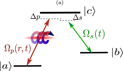
As an important feature of adiabatic interactions, there is a pronounced nonlinear dependence of coherent excitation probabilities versus the driving laser intensities. As an example, let us consider the adiabatic population transfer by STIRAP. The process requires two strong laser fields, i.e., a pump and a Stokes fields acting on atoms in a -type level scheme (see Fig. 1(a)). Let us assume that initially all atomic population is in the ground state . If we consider incoherent excitation with overlapping laser beams (as in conventional stimulated emission pumping (SEP), which is similar to the STED configuration), we expect that eventually an equal population is established in all three atomic states. Hence, the population transfer to the final state would be neither complete nor selective for the incoherent excitation. On the other hand, the coherent STIRAP process involving a counter-intuitive pulse sequence (the Stokes pulse preceding the pump pulse) enables a complete and selective population transfer from the state to the via the adiabatic following of the dark atomic dressed state during the atom-light interaction process [24, 25, 26, 27].
Adiabatic processes which require the driving laser intensities to exceed an adiabaticity threshold, exhibit a very strong nonlinear behaviour. Consequently, the spatial resolution of adiabatic excitation increases rapidly (much faster compared to the case of the incoherent excitation) with increasing the laser intensity, and is not limited by the diffraction. Spatially confined atomic excitation based on STIRAP is a fully coherent process that does not rely on the spontaneous emission, as the atoms adiabatically follow the dark state [15, 28, 29]. Therefore, it can be also important for systems, where coherence has to be preserved, e.g., atomic Bose-Einstein condensates (BECs), or for applications to the quantum information science. We note, that while the STIRAP technique has already found a multitude of applications [24, 25, 26, 27], thus far it has been rarely applied for high-precision atomic localization [15, 28, 29].
The first theory proposals and experimental investigations on adiabatically localized atomic excitations dealt with EIT (or CPT) [14, 12, 13, 17, 18, 19, 16, 30, 31, 32] rather than STIRAP [15, 28]. In EIT a dark dressed state emerges, which permits confinement of atomic excitation [14, 16]. In contrast to STIRAP with two strong and delayed pulses, EIT makes use of overlapping pulses with a weak probe and a strong coupling pulse. While STIRAP was developed for population transfer, EIT was initially designed to reduce absorption of a weak probe beam by suppressing excitation from the ground state coupled to the excited state by a stronger control (coupling) field [21, 22]. Note that in the case of the EIT the spatial confinement does not converge as fast as for STIRAP. The earlier localization protocols with standing waves create a periodic pattern of tightly localized regions, which was fine for the first experimental demonstrations [17, 18, 19], but it is not suitable for most applications which usually require single excitation regions.
To obtain a single excitation region (spot localization), here we combine the STIRAP with a STED-like beam geometry by expanding the initial idea for the STIRAP-based localization approach [15, 28]. The atoms are initially prepared in their ground state and subsequently adiabatically follow the dark state by applying the STIRAP scheme [24, 25, 26, 27], in which both pulses act in a counter-intuitive temporal sequence, the Stokes pulse preceding the pump one. In the following we assume a Stokes beam with a constant intensity across the interaction region, while the pump beam has a doughnut-like spatial profile. We also assume the latter to be an optical vortex carrying an orbital angular momentum (OAM) [33] (see Fig. 1(a)). In that case, atoms remain in their initial ground state when located at the vortex core (zero intensity) of the pump beam. On the other hand, away from the vortex core the atoms interacting with both the Stokes and the pump fields are transferred to the final state through the 2D STIRAP process. The atoms localized at the pump core are not excited by light and therefore do not suffer from recoil-induced broadening, which implies that the Raman-Nath approximation perfectly applies (see [34] and references therein). On the other hand, the atoms that change their internal state as a consequence of the STIRAP process do not suffer from spontaneous emission since the process is coherent. For the latter, the total momentum exchanged corresponds only to the momentum difference between the doughnut field and the traveling wave field, which is almost negligible if the energies of two internal states are close [28].
It should be pointed out that a similar configuration has been employed in Ref. [29] with Stokes pulse having a Bessel beam spatial profile, and the one of the pump being the result of superimposing two Bessel beams focused with a lateral offset, producing a node in its center. On the other hand, in our scheme, the pump carries an OAM while the Stokes has no spatial dependence, creating a spot localization. The OAM of pump beam allows manipulation of the degree of localization and creates side spots in localization pattern, a feature which is missing in Ref. [29].
Using such a 2D STIRAP method, one can imprint topological phase singularities on trapped atomic BECs, creating very narrow localized 2D density defects. Specifically, the phase of the vortex beam is transferred to the atoms during the STIRAP process, thus producing a 2D dark soliton (a vortex) for the BEC atoms in another internal state. On the other hand, the non-transferred atomic population makes a 2D bright soliton located at the vortex core. These two component defects (bright and dark solitons) are localized down to the order of a nanometer, thus circumventing the restriction set by the diffraction limit. We have carried numerical simulations of the Gross-Pitaevskii equation to study these subwavelength structures. The method is also useful for creating in a controllable way several dark and bright closely-spaced solitons for studying their dynamics and collisional properties.
II Basic theory
Let us consider an ensemble of atoms, characterized by a three-level -scheme of energy levels, as shown in Fig. 1(a). The scheme includes an initial atomic state , an intermediate excited level , and a target state . An atom positioned at interacts with a Stokes and a pump laser pulses arriving with a time delay characterizing the STIRAP process (Fig. 1(b)). The pulses are described by the following slowly changing envelopes of Rabi frequencies
| (1) |
| (2) |
where is a temporal width of the pulses.
The Stokes laser field is a travelling wave acting on the transition with a constant spatial profile . On the other hand, the transition is coupled by a doughnut-shaped Laguerre-Gaussian pump beam characterized by the transverse profile
| (3) |
where describes the cylindrical radius, is the beam waist, represents the strength of the doughnut beam and denotes the azimuthal angle with respect to the beam axis . Such a beam is characterized by the vorticity and carries an orbital angular momentum (OAM) per photon [33]. The Stokes and pump detunings from the transitions and are denoted by and , respectively. Assuming the one- and two-photon resonance , the quantum dynamics of the -type atom-light coupling can be described by the Hamiltonian under the electric dipole and Rotating-wave-approximation (RWA)
| (4) |
The destructive interference of excitation pathways from and up to ensures that a special superposition of ground states
| (5) |
known as the dark state is decoupled from both optical fields. The dark state is an eigenstate of the atom-light Hamiltonian (4) with a zero eigen-energy [35]. Here
is the total Rabi frequency. The dark state can be represented as
| (6) |
where
| (7) |
is the mixing angle.
III 2D STIRAP superlocalization method
The dark state (5) does not include the leaky excited state decaying with a rate . Therefore, the losses will be suppressed if the atomic system adiabatically follows the dark state . The present 2D STIRAP superlocalization protocol makes use of such an adiabatic following of the dark state for the counterintuitive ordering of the laser pulses shown in Fig. 1(b), with the Stokes pulse preceding the pump [24, 36], so that
| (8) |
This implies that
| (9) |
For such a pulse sequence, the dark state reduces to for and to for . This provides a suitable vehicle for transferring atoms from the initial state to the final state without populating the state . In order to maintain the system in the dark state, the process should be carried out satisfying a global adiabaticity condition [36, 37, 38, 28]
| (10) |
where is a dimensionless constant. For the optimal Gaussian profiles and overlapping times, the parameter takes values around [39, 28].
In this way, the atoms are initially in the internal state ; the Stokes field , which couples initially unpopulated states and , is sent before the vortex pump beam , the latter coupling the populated ground state with the excited state . As illustrated in Fig. 1(b)), the two pulses should overlap, so that the population could be transferred from the initial state to the final state during the STIRAP. In fact, if the temporal separation between the pulses is too large, the adiabaticity condition (10) fails to hold. The intensity of the pump beam goes to zero at the vortex core, preventing the atoms situated in this spatial region to be transferred to the final state . On the other hand, away from the vortex core, the atoms interacting with both the pump and Stokes fields are transferred to state through the 2D STIRAP process with a sufficiently large efficiency, see Appendix A. Therefore, if the amplitude of the vortex beam is considerably larger than the amplitude of the Stokes beam , a spot-like super-narrow spatial pattern can be generated at the core of a strong pump beam when measuring the population distribution of the atoms in the state .
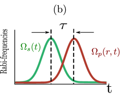
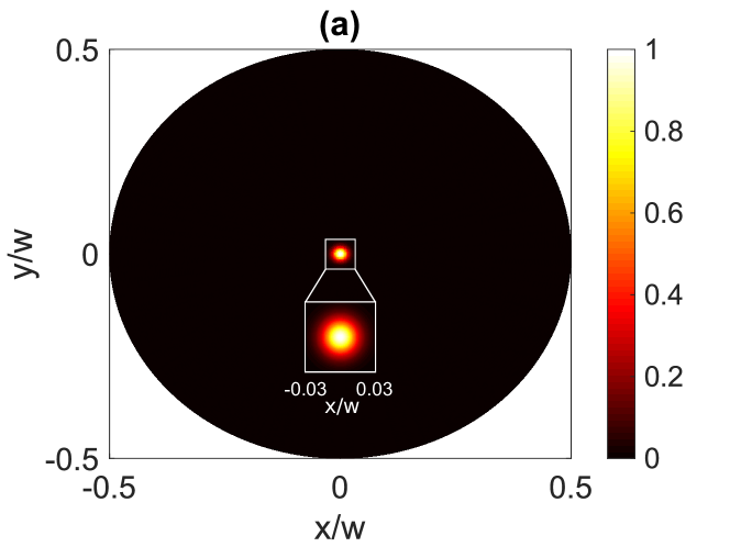
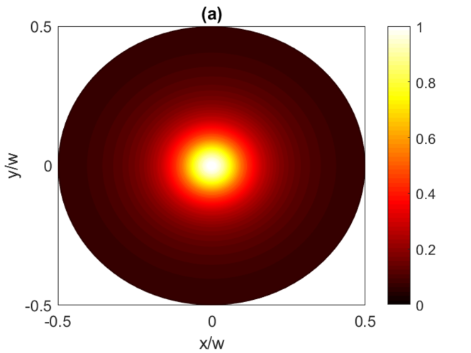
Figure. 2 depicts the population distribution of the internal state after applying the 2D STIRAP. The plots are obtained by numerically solving the corresponding density matrix equations of the system [40] for and different OAM numbers (a) and (b). For the atomic excitation is seen to be strongly concentrated at the zero intensity region of the pump field (at the core of vortex beam at ), indicating that the atoms can be well localized in a very narrow spot, much smaller than the beam waist (Fig. 2 (a)). From the inset in Fig. 2 (a) we deduce a resolution (full width at half maximum, FWHM) along the x direction to be 0.02 in units of the beam waist for . By taking the beam waist of m, we get a localization of 20nm, i.e. far below the diffraction limit. We checked by another numerical simulations (not shown in the paper) that the resolution reduces to about 8nm for , and further decreases for larger values of .
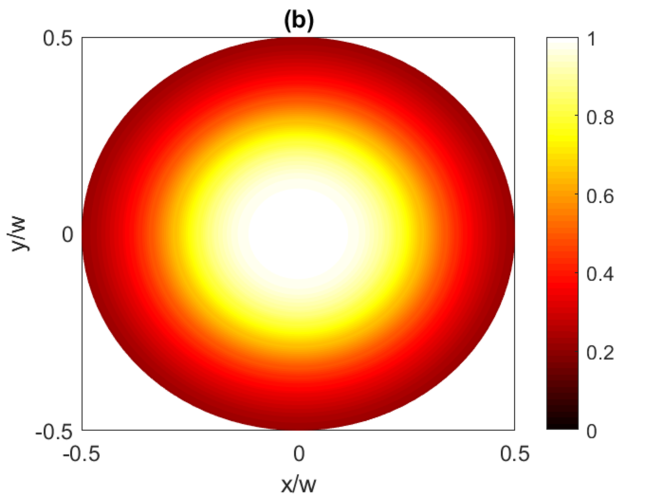
When the OAM number increases to , the spot width increases resulting in a lower localization precision, as can be seen in Fig. 2 (b). This is due to an increase of the core of the optical vortex for the laser beams with a larger vorticity. We also checked our results with a Stokes beam of Gaussian intensity profile in space. The numerical simulation confirms, that the Stokes beam profile does not matter, provided the adiabaticity condition is still satisfied.
It is worthwhile clarifying that an optical vortex can be generated by an intensity pattern with a Gaussian envelope that possesses a point singularity at the center of the optical vortex beam [41]. This can be done by implementing a lens arrangement to image the optical vortex intensity profile immediately after a spiral phase plate (SPP). However, such a vortex beam is not suitable for the purpose of atom localization. It is the doughnut shaped spatial profile of the pump which creates the spot localization, as those atoms located at the core of the pump beam (hollow core in the doughnut beam) remain in the initial state, creating the spot defects. The phase of the vortex beam in Eq. (3) only controls the resolution of localization, as shown in (Fig. 2 (a,b)).
III.1 STIRAP vs. CPT for spot localization
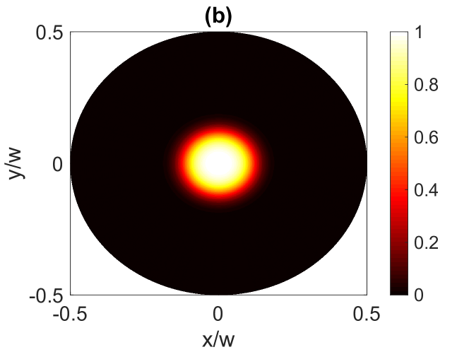
One can also achieve a spot-like localization in the three-level scheme illustrated in Fig. 1(a) by applying a CPT technique. In this case, a spot localization is possible when the system reaches the steady state through an optical-pumping process to the dark state involving several cycles of laser excitation and the spontaneous emission. The 2D STIRAP localization protocol described previously reduces to the 2D CPT case for the overlapping pump and Stokes pulses () with . In this case, an atom initially prepared in the state will end up in the dark state at the steady state if the two-photon resonance is maintained. As the intensity of the pump beam goes to zero at the vortex core, the dark state of the system reduces to the bare state there, as one can see in Eqs. (5) and (6). Hence the population distribution of the state shows a maximum at the center of the vortex beam.
In Fig. 3 we present the population of the state with different OAM numbers (a) and (b) after applying the 2D CPT protocol. The population distribution shows again a spot-like pattern at the center. One can see that the localization patterns can be well controlled by the OAM number , like in the case of the 2D STIRAP presented in Fig. 2. In both cases the narrowest spot structure could be always achieved with the minimum winding number () corresponding to the smallest core of the optical vortex. Yet, the localization precision is lower for the 2D CPT, indicating that the 2D STIRAP permits much stronger 2D confinement.
III.2 Off-axis spot localization
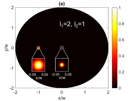
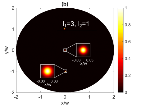
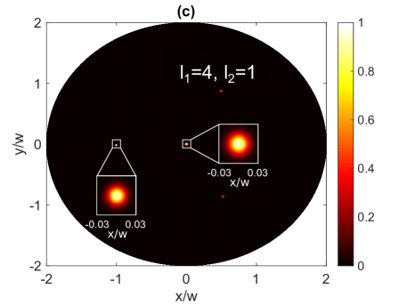
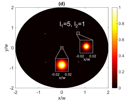
When two optical beams with different OAM numbers () are superimposed collinearly they generate a pattern of vortices that depends on the relative amplitude and phase of individual beams [42, 43]. We consider now such a superposition of two collinear component beams with topological charges and for the purpose of off-axis 2D STIRAP localization. In this case, the pump beam reads
| (11) |
where , and . The resulting composite beam contains a vortex of charge located at the beam center which is surrounded by peripheral vortices [42, 43]. Figure 4 shows the simulation of the spatial distribution of population in the state after applying the 2D STIRAP protocol and using the composite pump beam given by Eq. (11). One can see that the spatial profile of the population develops new off-axis atomic spots depending on the topological charges and , which enables single-site addressability of trapped arrays of atoms. These peripheral localization spots are evenly distributed at angles where and is an odd integer for each of the peripheral vortices.
IV Localized 2D bright and dark solitons in a trapped BEC
We now focus on a trapped BEC of to show a feasibility of generation of narrow structures in the condensate. We consider a zero temperature two-species BEC, with and . To study vortex imprinting in the BEC, the system is described by the 2D Gross-Pitaevskii equations (GPEs) for a three-component BEC involving also an intermediate excited state needed to perform the STIRAP. Yet the excited state is weakly populated if the adiabaticity condition (10) holds.
Before the Stokes and pump laser fields are applied, the BEC is prepared in the ground state with the wave-function obeying the stationary 2D GPE
| (12) |
with , where is the atomic mass, is the number of atoms in the condensate, indicates the chemical potential, is the harmonic trapping potential, is the cylindrical radius, is the angular frequency of the radial trap, describes the atom-atom interaction, is the -wave scattering length between the species and , and denotes the characteristic length of the transverse harmonic trap of the like pancake shape BEC with . The parameter values used in the simulations are , , , and [28].
Subsequently the 2D multi-component BEC interacts with two laser pulses characterized by Rabi-frequencies and . The atomic ground states described by wavefunctions and are coupled to the intermediate excited state described by the wavefunction . The GPEs for evolution of such a three-component BEC can be written as
| (13) |
with the initial conditions and . Here the trapping potential is the same for both ground states i.e., , the Rabi frequencies for the traveling wave and the vortex beam are given by Eqs. (1) and (2), and we have omitted the kinetic energy and trapping potential in the equations for the excited state wave-function. The parameter values used for the time evolution simulation are , , , , , , , , . The excited state decay is . The space is discretized by a grid, ranging from to in both directions, hence the minimal discernible distance is . The system is evolved for . The simulations are performed using the GPELab toolbox[44, 45].
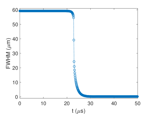
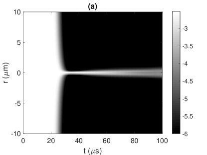
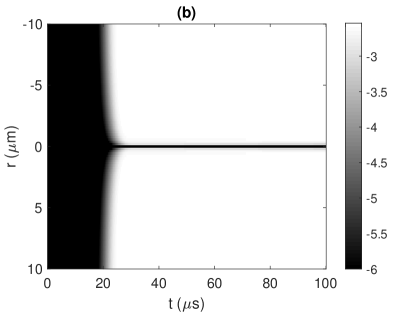
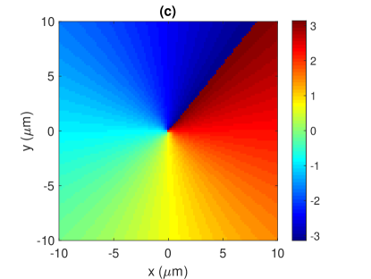
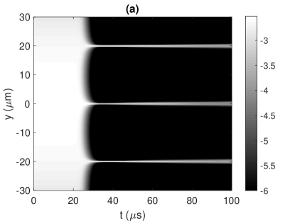
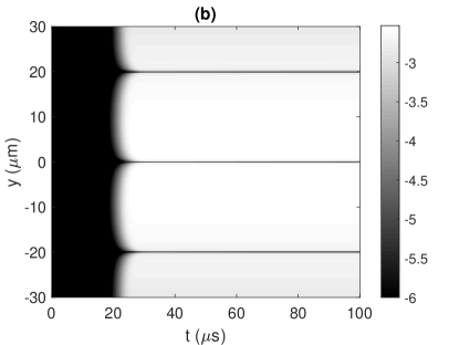
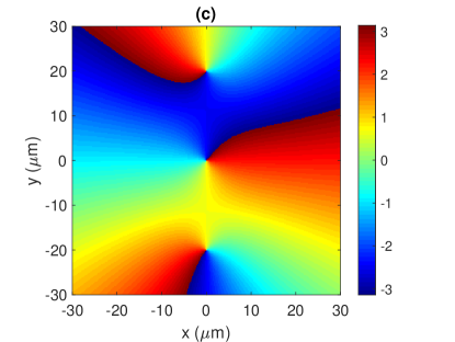
Figure 5 shows the full width at half maximum (FWHM) of the density of component as it evolves in time. Figures 6(a) and (b) show the time evolution of densities and along the radial direction, zooming in on the region from to where a localized density structure forms. One can see that after applying the pump and Stokes pulses the component develops an extremely narrow 2D spot-like structure at the core of vortex representing a 2D bright soliton that slowly disperses. A part of population which is transferred to the component creates a dark 2D soliton (a vortex), the phase profile of the vortex beam (Fig. 6(c)) being imprinted to this component via the 2D STIRAP. Thus one can create stable two component vector dark-bright solitons.
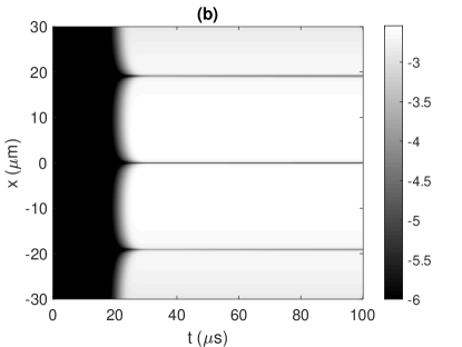
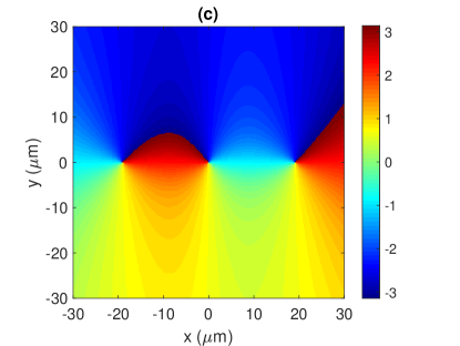
It is also possible to apply the 2D STIRAP protocol to the BEC by using multiple vortices centered at different positions to create several dark–bright defect structures with nanometer resolution. In Fig. 7, we consider the pump beam of the form given by Eq. 11 where , , , , and . On the other hand, if the beam shape is given by Eq. (11) with , and , the density evolution and phase profiles are presented in Fig. 8 where and . Clearly, several vortices are imprinted to the BEC component along the or directions, creating dark solitons. Multiple 2D structures with nanometer resolution are also patterned in the component (bright solitons) at positions where the 2D STIRAP process does not occur. The position of these 2D defects depends on the shape of original pump beam (11).

Note that there exist some other proposals to transfer optical vortices to BECs for creating the atomic defects [46, 47, 48, 49, 50, 51, 52, 53, 54, 55]. In particular, storing of the vortex slow light in the EIT configuration allows to transfer a small amount of atomic population to the other atomic internal ground state accompanied by the transfer of the vorticity to the atoms [47, 53, 54]. On the other hand, by applying the STIRAP with singular light beams to atomic BECs one can create localized excitations such as vortices [46] and solitons [15] with a more significant population transfer and without the diffraction limitations occurring, e.g., in traditional ways of creating vortices [56, 57] and dark solitons [58, 59, 60] in BECs via the phase imprinting. In the method presented in ref. [46], the -type BEC initially prepared in its ground level is exposed to two copropagating laser pulses, viz. a nonvortex pump beam and a vortex Stokes (dump) beam. This allows the transfer of angular momentum from the Stokes field to the matter, creating a vortex BEC in another atomic internal state. Yet, the method does not allow one to create simultaneously a tightly localized 2D atomic population in the initial atomic state at the vortex core of the Stokes beam, as in this spatial region the atoms experience the absorption losses by a non-vortex pump beam. Such a problem does not appear in the present setup, as it is now the pump beam which carries an OAM with a zero population at the vortex core. Thus one can create 2D two-component dark-bright solitons described above. The present 2D STIRAP method has also some similarities to the one considered in [15] for formation of two component (vector) solitons. Yet, ref. [15] dealt with the 1D defects which are imprinted on the BEC via its interaction with the first order Hermite–Gaussian mode and another two Gaussian modes used in the tripod STIPAP process. On the other hand, the current 2D STIRAP method involving the Laguere-Gaussian mode permits generation of the 2D defects in the BEC.
The dark–bright defect structures proposed to generate in this paper can be measured via the standard time of flight and absorption imaging. Yet it is a destructive measurement. On the other hand, phase-contrast imaging, allowing the non-destructive measurement of condensate samples in situ [61], has proven to be a useful technique to monitor vortices in Bose Einstein condensates. In particular, this technique has been used to observe vortices with the core filled by a second component [62], so it can also be applied to our proposal.
V Concluding Remarks
In summary, we have proposed a new method of 2D superlocalization and patterning of atomic matter waves well beyond the diffraction limit. For this we use two laser fields with a certain time delay, an optical vortex pump as well as a Stokes pulses, interacting with three internal levels of the matter wave. This configuration yields state-selective strongly confined spot-like superlocalization patterns at the vortex cores of the pump beams where the 2D STIRAP process does not take place due to vanishing pump field. We have shown that the proposed method can be implemented to imprint high contrast 2D defects with nanometer resolution on an atomic BEC in a very controllable way. Using this method one can also create stable multiple bright and dark solitons close to each other with a full control over their size and position. In this way, the present method allows to circumvent the restriction set by the diffraction limit creating a variety of subwavelength structures.
Appendix A: Population transfer efficiency
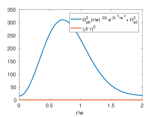
The transfer efficiency should be sufficiently large, otherwise the localization will wash out. The higher is the intensity, the better is the transfer. From Fig. 2 of the manuscript, we see that the transfer efficiency is close to outside the region of zero intensity in the laser profile. This figure shows the remaining population after pumping. Since the transfer is efficient, only a narrow density peak remains; otherwise we would see a wider (or washed out) peak. This depends upon the adiabaticity criterion given by Eq. 10. To clarify this point, we plot in Fig. 9 a 2D simulation of the spatial dependence of the adiabaticity criterion for the same parameters used in Fig. 2(a). Note that the blue line shows the left hand side while the red line corresponds to the right hand side in Eq. 10. The peak value of the criterion obviously shows that the condition is always satisfied for our selected parameters, allowing a high transfer efficiency.
Funding
European Social Fund (09.3.3-LMT-K-712-19-0031); Ministerio de Economìa y Competitividad, MINECO, (FIS2017- 86530-P and PID2020-118153GB-I00); Generalitat de Catalunya (SGR2017-1646); European Union Regional Development Fund within the ERDF Operational Program of Catalunya (project QUASICAT/QuantumCat); European Cooperation in Science and Technology (CA16221).
Acknowledgments
This work has received funding from European Social Fund (Project
No. 09.3.3-LMT-K-712-19-0031) under grant agreement with the Research
Council of Lithuania (LMTLT) for H.R.H.
Disclosures
The authors declare no conflicts of interest.
Data availability
Data underlying the results presented in this paper are not publicly available at this time but may
be obtained from the authors upon reasonable request.
References
- Monroe et al. [1995] C. Monroe, D. M. Meekhof, B. E. King, W. M. Itano, and D. J. Wineland, Demonstration of a fundamental quantum logic gate, Phys. Rev. Lett. 75, 4714 (1995).
- Cirac and Zoller [1995] J. I. Cirac and P. Zoller, Quantum computations with cold trapped ions, Phys. Rev. Lett. 74, 4091 (1995).
- Isenhower et al. [2010] L. Isenhower, E. Urban, X. L. Zhang, A. T. Gill, T. Henage, T. A. Johnson, T. G. Walker, and M. Saffman, Demonstration of a neutral atom controlled-not quantum gate, Phys. Rev. Lett. 104, 010503 (2010).
- Wilk et al. [2010] T. Wilk, A. Gaëtan, C. Evellin, J. Wolters, Y. Miroshnychenko, P. Grangier, and A. Browaeys, Entanglement of two individual neutral atoms using rydberg blockade, Phys. Rev. Lett. 104, 010502 (2010).
- Staliunas et al. [2002] K. Staliunas, S. Longhi, and G. J. de Valcárcel, Faraday patterns in bose-einstein condensates, Phys. Rev. Lett. 89, 210406 (2002).
- Modugno et al. [2006] M. Modugno, C. Tozzo, and F. Dalfovo, Detecting phonons and persistent currents in toroidal bose-einstein condensates by means of pattern formation, Phys. Rev. A 74, 061601 (2006).
- Hell [2007] S. W. Hell, Far-field optical nanoscopy, Science 316, 1153 (2007).
- Rubio et al. [2013a] J. L. Rubio, D. Viscor, V. Ahufinger, and J. Mompart, Nanoscale resolution for fluorescence microscopy via adiabatic passage, Optics Express 21, 22139 (2013a).
- Thywissen and Prentiss [2005] J. H. Thywissen and M. Prentiss, Demonstration of frequency encoding in neutral atom lithography, New J. Phys. 7, 47 (2005).
- Hell [2009] S. W. Hell, Microscopy and its focal switch, Nature Methods 6, 24 (2009).
- Puthukodan et al. [2020] S. Puthukodan, E. Murtezi, J. Jacak, and T. A. Klar, Localization sted (locsted) microscopy with 15 nm resolution, Nanophotonics 9, 783 (2020).
- Paspalakis and Knight [2001] E. Paspalakis and P. L. Knight, Localizing an atom via quantum interference, Phys. Rev. A 63, 065802 (2001).
- Sahrai et al. [2005] M. Sahrai, H. Tajalli, K. T. Kapale, and M. S. Zubairy, Subwavelength atom localization via amplitude and phase control of the absorption spectrum, Phys. Rev. A 72, 013820 (2005).
- Agarwal and Kapale [2006] G. S. Agarwal and K. T. Kapale, Subwavelength atom localization via coherent population trapping, J. Phys. B: At. Mol. Opt. Phys. 39, 3437 (2006).
- Juzeliūnas et al. [2007] G. Juzeliūnas, J. R. P.Ohberg, and M. Fleischhauer, Formation of solitons in atomic bose - einstein condensates by dark-state adiabatic passage, Lith. J. Physs. 47, 351 (2007).
- Gorshkov et al. [2008] A. V. Gorshkov, L. Jiang, M. Greiner, P. Zoller, and M. D. Lukin, Coherent quantum optical control with subwavelength resolution, Phys. Rev. Lett. 100, 093005 (2008).
- Proite et al. [2011] N. A. Proite, Z. J. Simmons, and D. D. Yavuz, Observation of atomic localization using electromagnetically induced transparency, Phys. Rev. A 83, 041803 (2011).
- Miles et al. [2013] J. A. Miles, Z. J. Simmons, and D. D. Yavuz, Subwavelength localization of atomic excitation using electromagnetically induced transparency, Phys. Rev. X 3, 031014 (2013).
- Miles et al. [2015] J. A. Miles, D. Das, Z. J. Simmons, and D. D. Yavuz, Localization of atomic excitation beyond the diffraction limit using electromagnetically induced transparency, Phys. Rev. A 92, 033838 (2015).
- Alzetta et al. [1976] G. Alzetta, A. Gozzini, L. Moi, and G. Orriols, An experimental method for the observation of r.f. transitions and laser beat resonances in oriented na vapour, Nuovo Cimento B 36, 5 (1976).
- Harris [1997] S. E. Harris, Electromagnetically induced transparency, Physics Today 50, 36 (1997).
- Fleischhauer et al. [2005] M. Fleischhauer, A. Imamoglu, and J. P. Marangos, Electromagnetically induced transparency: Optics in coherent media, Rev. Mod. Phys. 77, 633 (2005).
- Heinze et al. [2013] G. Heinze, C. Hubrich, and T. Halfmann, Stopped light and image storage by electromagnetically induced transparency up to the regime of one minute, Phys. Rev. Lett. 111, 033601 (2013).
- Bergmann et al. [1998a] K. Bergmann, H. Theuer, and B. W. Shore, Coherent population transfer among quantum states of atoms and molecules, Rev. Mod. Phys. 70, 1003 (1998a).
- Ivanov et al. [2004] P. A. Ivanov, N. V. Vitanov, and K. Bergmann, Effect of dephasing on stimulated raman adiabatic passage, Phys. Rev. A 70, 063409 (2004).
- Vitanov et al. [2017a] N. V. Vitanov, A. A. Rangelov, B. W. Shore, and K. Bergmann, Stimulated raman adiabatic passage in physics, chemistry, and beyond, Rev. Mod. Phys. 89, 015006 (2017a).
- Klein et al. [2008] J. Klein, F. Beil, and T. Halfmann, Experimental investigations of stimulated raman adiabatic passage in a doped solid, Phys. Rev. A 78, 033416 (2008).
- Mompart et al. [2009] J. Mompart, V. Ahufinger, and G. Birkl, Coherent patterning of matter waves with subwavelength localization, Phys. Rev. A 79, 053638 (2009).
- Rubio et al. [2013b] J. L. Rubio, D. Viscor, V. Ahufinger, and J. Mompart, Nanoscale resolution for fluorescence microscopy via adiabatic passage, Optics Express 21, 22139 (2013b).
- Shui et al. [2015] T. Shui, Z. Wang, and B. Yu, Efficient two-dimensional atom localization via spontaneously generated coherence and incoherent pump, Journal of the Optical Society of America B 32, 210 (2015).
- Singh et al. [2019] N. Singh, R. Kumar, and A. Wasan, Effect of nearby levels on atom localization in the atomic system via spatial dependent probe absorption, OSA Continuum 2, 862 (2019).
- Dutta et al. [2020] B. K. Dutta, P. Panchadhyayee, I. Bayal, N. Das, and P. K. Mahapatra, Optical absorption microscopy of localized atoms at microwave domain: two-dimensional localization based on the projection of three-dimensional localization, Scientific Reports 10, 536 (2020).
- Allen et al. [1999] L. Allen, M. J. Padgett, and M. Babiker, Iv the orbital angular momentum of light, Progress in Optics 39, 291 (1999).
- Meystre [2001] P. Meystre, Atom Optics (Springer, New York, 2001).
- Scully and Zubairy [1997] M. O. Scully and S. Zubairy, Quantum optics, edited by C. U. Press (Cambridge University Press, 1997).
- Bergmann et al. [1998b] K. Bergmann, H. Theuer, and B. W. Shore, Coherent population transfer among quantum states of atoms and molecules, Rev. Mod. Phys. 70, 1003 (1998b).
- Vitanov et al. [2017b] N. V. Vitanov, A. A. Rangelov, B. W. Shore, and K. Bergmann, Stimulated raman adiabatic passage in physics, chemistry, and beyond, Rev. Mod. Phys. 89, 015006 (2017b).
- Shore [2017] B. W. Shore, Picturing stimulated raman adiabatic passage: a stirap tutorial, Advances in Optics and Photonics 9, 563 (2017).
- Kuklinski et al. [1989] J. R. Kuklinski, U. Gaubatz, F. T. Hioe, and K. Bergmann, Adiabatic population transfer in a three-level system driven by delayed laser pulses, Phys. Rev. A 40, 6741 (1989).
- Jyotsna and Agarwal [1995] I. V. Jyotsna and G. S. Agarwal, Coherent population trapping at low light levels, Phys. Rev. A 52, 3147 (1995).
- Rumala and Leanhardt [2017] Y. S. Rumala and A. E. Leanhardt, Optical vortex with a small core and gaussian intensity envelope for light-matter interaction, Journal of the Optical Society of America B 34, 909 (2017).
- Franke-Arnold et al. [2007] S. Franke-Arnold, J. Leach, M. J. Padgett, V. E. Lembessis, D. Ellinas, A. J. Wright, J. M. Girkin, and P. O. A. S. Arnold, Optical ferris wheel for ultracold atoms, Optics Express 15, 8619 (2007).
- Baumann et al. [2009] S. M. Baumann, D. M. Kalb, L. H. MacMillan, and E. J. Galvez, Propagation dynamics of optical vortices due to gouy phase, Optics Express 17, 9818 (2009).
- Antoine and Duboscq [2014] X. Antoine and R. Duboscq, GPELab, a Matlab toolbox to solve Gross–Pitaevskii equations I: Computation of stationary solutions, Comput. Phys. Commun. 185, 2969 (2014).
- Antoine and Duboscq [2015] X. Antoine and R. Duboscq, GPELab, a Matlab toolbox to solve Gross–Pitaevskii equations II: Dynamics and stochastic simulations, Comput. Phys. Commun. 193, 95 (2015).
- Nandi et al. [2004] G. Nandi, R. Walser, and W. P. Schleich, Vortex creation in a trapped bose-einstein condensate by stimulated raman adiabatic passage, Phys. Rev. A 69, 063606 (2004).
- Dutton and Ruostekoski [2004] Z. Dutton and J. Ruostekoski, Transfer and storage of vortex states in light and matter waves, Phys. Rev. Lett. 93, 193602 (2004).
- Kapale and Dowling [2005] K. T. Kapale and J. P. Dowling, Vortex phase qubit: Generating arbitrary, counterrotating, coherent superpositions in bose-einstein condensates via optical angular momentum beams, Phys. Rev. Lett. 95, 173601 (2005).
- Andersen et al. [2006] M. F. Andersen, C. Ryu, P. Cladé, V. Natarajan, A. Vaziri, K. Helmerson, and W. D. Phillips, Quantized rotation of atoms from photons with orbital angular momentum, Phys. Rev. Lett. 97, 170406 (2006).
- Pugatch et al. [2007] R. Pugatch, M. Shuker, O. Firstenberg, A. Ron, and N. Davidson, Topological stability of stored optical vortices, Phys. Rev. Lett. 98, 203601 (2007).
- Wright et al. [2008] K. C. Wright, L. S. Leslie, and N. P. Bigelow, Optical control of the internal and external angular momentum of a bose-einstein condensate, Phys. Rev. A 77, 041601 (2008).
- Simula et al. [2008] T. P. Simula, N. Nygaard, S. X. Hu, L. A. Collins, B. I. Schneider, and K. Mølmer, Angular momentum exchange between coherent light and matter fields, Phys. Rev. A 77, 015401 (2008).
- Ruseckas et al. [2011] J. Ruseckas, A. Mekys, and G. Juzeliūnas, Slow polaritons with orbital angular momentum in atomic gases, Phys. Rev. A 83, 023812 (2011).
- Ruseckas et al. [2013] J. Ruseckas, V. c. v. Kudriašov, I. A. Yu, and G. Juzeliūnas, Transfer of orbital angular momentum of light using two-component slow light, Phys. Rev. A 87, 053840 (2013).
- Hou et al. [2017] J. Hou, X.-W. Luo, K. Sun, and C. Zhang, Adiabatically tuning quantized supercurrents in an annular bose-einstein condensate, Phys. Rev. A 96, 011603 (2017).
- Dobrek et al. [1999] L. Dobrek, M. Gajda, M. Lewenstein, K. Sengstock, G. Birkl, and W. Ertmer, Optical generation of vortices in trapped bose-einstein condensates, Phys. Rev. A 60, R3381 (1999).
- Andrelczyk et al. [2001] G. Andrelczyk, M. Brewczyk, L. Dobrek, M. Gajda, and M. Lewenstein, Optical generation of vortices in trapped bose-einstein condensates, Phys. Rev. A 64, 043601 (2001).
- Denschlag et al. [2000] J. Denschlag, J. E. Simsarian, D. L. Feder, C. W. Clark, L. A. Collins, J. Cubizolles, L. Deng, E. W. Hagley, K. Helmerson, W. P. Reinhardt, S. L. Rolston, B. I. Schneider, and W. D. Phillips, Generating solitons by phase engineering of a bose-einstein condensate, Science 287, 97 (2000).
- Burger et al. [1999] S. Burger, K. Bongs, S. Dettmer, W. Ertmer, K. Sengstock, A. Sanpera, G. V. Shlyapnikov, and M. Lewenstein, Dark solitons in bose-einstein condensates, Phys. Rev. Lett. 83, 5198 (1999).
- Wu et al. [2002] B. Wu, J. Liu, and Q. Niu, Controlled generation of dark solitons with phase imprinting, Phys. Rev. Lett. 88, 034101 (2002).
- Andrews et al. [1996] M. R. Andrews, M.-O. Mewes, N. J. van Druten, D. S. Durfee, D. M. Kurn, and W. Ketterle, Direct, nondestructive observation of a bose condensate, Science 273, 84 (1996).
- Anderson et al. [2000] B. P. Anderson, P. C. Haljan, C. E. Wieman, and E. A. Cornell, Vortex precession in bose-einstein condensates: Observations with filled and empty cores, Phys. Rev. Lett. 85, 2857 (2000).