Coupling, lifetimes and “strong coupling” maps for single molecules at plasmonic interfaces
Abstract
The interaction between excited states of a molecule and excited states of metal nanostructure (e.g. plasmons) leads to hybrid states with modified optical properties. When plasmon resonance is swept through molecular transition frequency an avoided crossing may be observed, which is often regarded as a signature of strong coupling between plasmons and molecules. Such strong coupling is expected to be realized when , where and are the molecule-plasmon coupling and the spectral width of the optical transition respectively. Because both and strongly increase with decreasing distance between a molecule and a plasmonic structure it is not obvious that this condition can be satisfied for any molecule-metal surface distance. In this work we investigate the behavior of and for several geometries. Surprisingly, we find that if the only contributions to are lifetime broadenings associated with the radiative and nonradiative relaxation of a single molecular vibronic transition, including effects on molecular radiative and nonradiative lifetimes induced by the metal, the criterion is easily satisfied by many configurations irrespective of the metal-molecule distance. This implies that the Rabi splitting can be observed in such structures if other sources of broadening are suppressed. Additionally, when the molecule-metal surface distance is varied keeping all other molecular and metal parameters constant, this behavior is mitigated due to the spectral shift associated with the same molecule-plasmon interaction, making the observation of Rabi splitting more challenging.
Department of Physics, Arizona State University, Tempe, AZ 85287, USA \altaffiliationSchool of Chemistry, Tel Aviv University, Tel Aviv 69978, Israel \SectionNumbersOn
1 Introduction
Plasmonic excitations occurring in small nanoparticles provide an interesting avenue for light and energy manipulation below the diffraction limit. Collective excitations of the electrons in the nanoparticle can couple to nearby molecules, and applications in nano-optics1, 2, 3, 4, nanosensing5, 6, 7, 8, 9, nanocatalysis10, 11, 12, 13, 14, 15, 16, 17, 18, 19, 20, plasmonic photosynthesis21, 22, 23, quantum information24, 25 and energy-harvesting technologies26, 27, 28, 29, 30, 31 have emerged.
In standard molecular spectroscopy and photochemistry, the molecule-photon encounter is essentially described as a scattering process that results in both species changing their quantum states (eigenstates of their respective Hamiltonians), with the added provision that the photon species is not conserved and can be converted to other forms of molecular energy. The molecule-photon coupling weighted by the density of photon states is weak, as exemplified by the relatively slow spontaneous emission rates ( for allowed electronic transitions), although using a high-intensity radiation field can lead to a strong and often non-linear molecular response. Different situations are encountered when the molecule interacts with one or a few localized photon mode(s), as encountered in optical cavities32, 33, 34, 35, 36, 37. Coupling to such modes is strong because of their localized nature, and the system response is best described in terms of hybrid radiation-matter states (polaritons) that diagonalize the strongly coupled part of the Hamiltonian, which include the molecule, these localized modes and their mutual interaction. The most prominent manifestation of this hybridization is the avoided crossing (Rabi splitting, ), observed in the optical response of such systems when the molecular transition frequency approaches and crosses a cavity mode frequency. Importantly, because the cavity photon interacts through the transition dipole of the whole molecular system, the coupling strength reflected in the observed splitting depends also on the number of molecules and is given by if the molecular aggregate is much smaller than the cavity mode wavelength. Here is the coupling parameter of a dipole (representing the transition dipole of a single molecule) to the radiative mode, given for a rectangular cavity of volume and dielectric constant by . By this experimental measure, “strong coupling” is often defined by the observability of this spectral structure, namely by the condition , where is the width of the polaritonic peaks. The possible consequences of strong coupling for transport phenomena38, 39, 40, 41, 42, 43, 44, 45, 46 and chemical rates35, 47, 48, 49, 29, 50, 51, 52, 53, 54, 55, 56, 57, 58, 59, 60, 61, 62, 63, 64, 65, 66, 67, 68, 69, 70 have been subject to intense discussion over the last decade.
Along with Fabri-Pérot type cavities, where the localization length is limited by the optical mode wavelength and is bounded by the cavity size, strong coupling phenomena are also observed in interacting plasmon-exciton systems71, 72, 73, 74. In particular, metallic nanostructures offer alternative setups for localization of electromagnetic modes, where considerably higher dissipation rates due to losses in the metal constituents are compensated by the considerably smaller, sub-wavelength localization volumes. Intermetallic gaps between plasmonic structures are known to support particularly strong localization. Such localities have been identified as “hotspots” in studies of surface-enhanced spectroscopies75, 76, 77, 78, and are now referred to as plasmonic cavities79, 80, 81, 82, 83, 84. A cavity-like structure is not, however, an absolute requirement. It was recently pointed out that strong coupling, as defined above, may be realized even in the vicinity of single plasmonic particles85, 86, 87, 88.
In addition to the usual spectroscopic implications (i.e. the observed Rabi splitting), the emergence of strong coupling in plasmonic cavities and other localities characterized by strong focusing of the electromagnetic field suggests, as pointed out above, that other dynamical processes may be modified in such strong coupling situations. In particular, while photochemical processes can be enhanced or induced at plasmonic interfaces due to the focused nature of the local EM field89, 90 or as a consequence of plasmon-induced generation of hot electrons91, 92, strong coupling induced modification of inter and intra-molecular interactions may lead to new or modified chemistry even without incident light65, 93, 94, 95.
With the latter possibility in mind, in this paper we study the emergence of light-matter strong coupling near several prototype plasmonic structures, aiming to map the phenomenon as a function of nanostructure geometry and molecular position and orientation. This study is motivated by three related considerations. First, while even in Fabri-Pérot-like cavities coupling of molecules to the cavity mode(s) depends on the molecular position in the cavity96, this dependence is expected to be much more pronounced near plasmonic structures. Secondly, while in Fabri-Pérot cavities strong coupling can be observed only with relatively large molecular ensembles, the much smaller volume of their plasmonic counterparts makes it possible to observe this phenomenon down to a single nanodot80, 88, 97, 98, 99 and even a single molecule85, 100, 101, 102. In the latter case, averaging over molecular orientation is not an option and orientation dependence should be addressed explicitly. Yet another important factor is the geometry of the plasmonic structure that can be used to tune the plasmonic resonance. Here we examine the dependence of strong coupling as experienced by a single molecule, represented by a point-dipole and positioned near metallic spheres, ellipsoids and bispherical dimers, on these structural parameters.
Finally, as defined, a practical manifestation of “strong coupling” is a relative concept: The possibility to observe Rabi splitting in the optical response of a metal-plasmonic structure composite reflects not only the magnitude of the molecule-radiation field coupling, an intrinsic property of this composite, but also the linewidth which can have many origins including spectral connection within the molecule as well as its interaction with the thermal environment. Limiting ourselves to lifetime broadening, it is often the case that, at close proximity to a metal structure, this attribute of the optical response is also dominated by the molecule-metal interaction, namely by effect of the metal structure on the radiative and non-radiative relaxation of the excited molecule. It is therefore useful to examine the relative magnitudes of the molecule-plasmon coupling strength and the metal induced lifetime broadening as providing an intrinsic bound to the presence of strong coupling as manifested by the observability of strong coupling. A recent observation of Rabi splitting in the zero-phonon line of a single molecule located in a plasmonic cavity at low temperature103 suggests that “strong coupling” may be more pervasive in such systems and can be observed if other sources of spectral line broadening are eliminated.
While light-matter interaction has important quantum ramifications, the information needed to establish the occurrence of strong coupling can be obtained from classical considerations and we invoke this approach in the present study. Furthermore, our focus on nanoparticles and their close vicinity makes it possible to ignore retardation effects and work in the electrostatic limit. Furthermore, we represent the molecule as a point-dipole emitter. While such a model is useful for mapping regions of strong coupling about the considered nanostructures, it should be kept in mind that any realistic calculation on a specific molecule should take its finite size and specific structure into account104.
2 Models and method
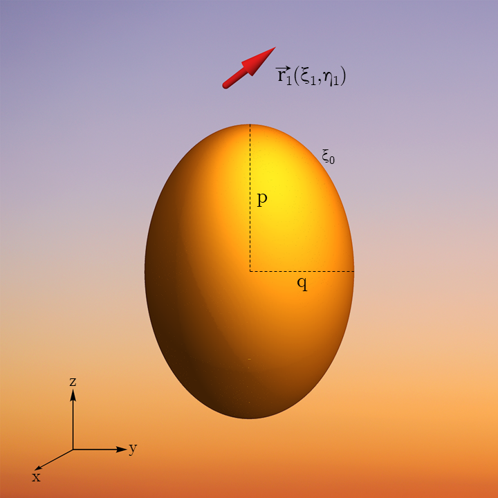
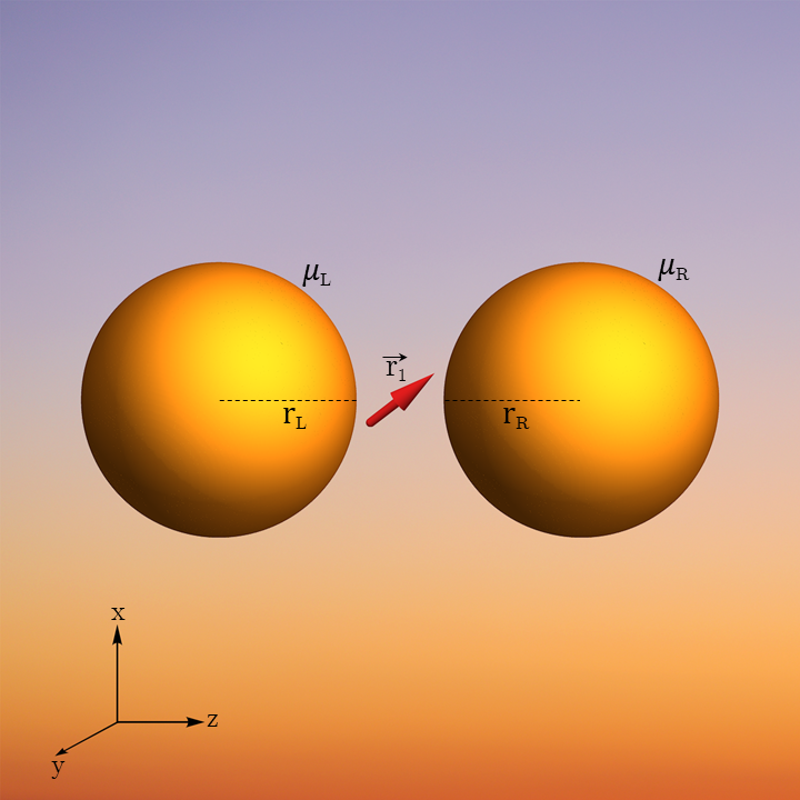
Figure 1 displays the models used in this study. The plasmonic system comprises of either a metallic ellipsoid (that includes a sphere as a limiting case), shown in Figure 1a, or a metallic bispherical dimer, shown in Figure 1b – systems for which analytical solutions to the relevant electrostatic boundary value problem can be obtained. The metal is represented as a continuum dielectric whose dielectric response function is given in the Drude form
| (1) |
where is the background permittivity from the bound electrons in the metal, is the bulk plasma frequency and is a phenomenological damping constant. In the calculations presented below the following parameters were used: for gold105: , eV rad/s, and eV rad/s, and for silver106: , eV rad/s, and eV rad/s. These metal particles are embedded in a uniform dielectric environment with a dielectric constant , taken to be 1. Other model dielectric functions can, of course, be used. In particular, to include effects of interband transition in the metal or the motion of the ionic core, one often considers Drude-Lorentz type dielectric response functions107. The molecule is taken as a point-dipole characterized by its magnitude and its position and orientation relative to the plasmonic structure. Finite molecular size effects can be considered as described in Ref. (104) but are disregarded in the present calculation.
The consequences of coupling between a dipole emitter and a plasmonic nanostructure can be calculated in terms of the Dyadic Green’s function that describes the response at to a point-current positioned at a given location and orientation relative to this plasmonic structure108. In particular, for a dipole oscillating at frequency this Green’s function yields the field associated with the oscillating dipole, leading to the interaction between the dipole and the plasmonic system in the form where is the transition dipole between the relevant states 1 and 2 of the molecular emitter and its direction reflects the molecular orientation in space, and is the electric field associated with the response of the plasmonic structure to this dipole, calculated at the dipole position. In the quantum case and are replaced by their quantum operators counterparts, but classical considerations are known to be sufficient for the present purpose109, 110, 111, 112, 113, 114. The relaxation induced by the plasmonic nanostructure can be obtained from the same calculation: at steady state, the energy dissipation rate can be obtained from the average work per unit time that this field does on the oscillating dipole. Furthermore for a dipole oscillating in an environment characterized by a real dielectric response function, the spontaneous radiative relaxation rate can be described by the golden rule, in terms of the local density of states , providing an elegant framework for analyzing the effect of an inhomogeneous dielectric environment on the emission rate (Purcell effect).
In the electrostatic limit and point-dipole emitter model considered here, this formulation can be made significantly simpler and can take two forms. First, following Gersten and Nitzan111, the point-dipole, positioned at , is assumed to oscillate with constant amplitude (taken as the transition dipole of the molecular emitter) and frequency , thereby driving the nearby plasmonic structure. The Laplace equation is solved for given (Eq. (1)) and and standard boundary conditions at the surface of the dielectric nanostructure to yield the electrostatic potential and electric field anywhere in the system (excluding the point occupied by the dipole) and in particular in the volume occupied by the nanostructure. Furthermore, the reaction field – the part of the field that arises from the polarization induced in the dielectric structure is obtained as where is the field of the bare dipole. Note that these response functions depend on through the frequency dependence of and that retardation effects are insignificant for the assumed small system. Also note that the linear response nature of standard electrostatics implies that these responses are linear in the driving dipole .
The calculation then proceeds in the following way:
-
1.
For the given dipole-nanostructure configuration, and a dipole oscillating with a frequency according to
(2) the local electric field associated with the polarization induced by the dipole in the nanostructure (the reaction field) is calculated. The component of this field, calculated at the dipole position and in the dipole direction, is used to define the needed component of the Green’s function:
(3) This is essentially the electrostatic limit of the relevant component of the Dyadic Green’s function mentioned above (calculated at the dipole position) except that the term associated with the bare dipole field is ignored.
-
2.
The coupling between the dipole emitter and the plasmonic nanostructure, at a frequency of a plasmon peak, is estimated using the following approximate procedure. First, the interaction of the dipole with the nanostructure is written in the form
(4) where is a dimensionless coordinate associated with the nanostructure, whose deviation from zero describes the polarization of this structure, and is the field associated with this polarization at the position and direction of the dipole. If the deviation of from zero is induced by the dipole, then . In the quantum analog of Eq. (4), is the electric field operator at the molecular position and is the molecular dipole operator. The coupling is given by the matrix element between the state , in which the molecule is in the ground state and the field has one photon, and the state , where the molecule is in the excited state and the field has photon (with the actual field amplitude accounted by the parameter ):
(5) Our task is to find . In a vacuum system of volume
(6) It is worth pointing that is the classical analogue to the quantum expression of the electric field . To evaluate for a given molecule-nanostructure configuration we assume that the underlying dynamics associated with the plasmonic peak at is that of a damped harmonic oscillator
(7) The term on the right222The factor on the right side enters to make dimensionless (distance is measured in units of ). is the force exerted on by its interaction with the dipole as derived from Eq. (4). is the transition frequency of the free emitter. The long time solution of Eq. (7) under driving in (2) is where
whence
(8) The field-dipole coupling parameter is estimated by using the Laplace equation to obtain the reaction field at the position of a driving dipole near the metal nanostructure, and fitting to the form given by Eq. (8). In Section 4 we present the so obtained coupling parameter in terms of an effective volume defined by
(9) -
3.
The total dipole moment of the composite system, , is calculated as where is the dipole induced on the nanostructure which is obtained as the following integral over the nanoparticle volume :
(10) - 4.
-
5.
The non-radiative relaxation affected by the presence of the dielectric nanostructure is calculated as the rate of Ohmic heat generation on the nanostructure115, given by the following integral over the nanostructure volume:
(12) In addition to the non-radiative relaxation rate associated with dissipation in the dielectric nanostructure, an intrinsic molecular component, denoted , results from the interaction of the molecule with its thermal environment and, for large molecules, also with intramolecular relaxation processes. This relaxation is molecule specific and cannot be quantitatively accounted for in our generic model. In the calculations reported below, unless otherwise stated, we have taken this intrinsic molecular relaxation rate to be equal to the radiative decay rate of the free molecule, implying that the emission yield of the free molecule is .
-
6.
The emission quantum yield of the molecular emitter- plasmonic nanostructure system is given by
(13) - 7.
The above calculation scheme provides a rather straightforward, albeit approximate, procedure for mapping strong coupling regions in a system of coupled nanostructure and molecular emitter, where the driving frequency is naturally taken to be the relevant molecular transition frequency . It suffers, however from a drawback, originating from the fact that since the dipole emitter is assumed to drive the system, such calculation cannot account for any spectral shift that is another manifestation of the molecule-radiation field coupling. The criterion (14), in which the coupling and relaxation rates are calculated for the driving frequency , may thus be viewed as an approximate criterion for the onset of strong coupling, but may not fully account for the spectral structure and dynamics beyond it.
To overcome the latter limitation the calculation should be done self-consistently (see, e.g., Refs 116, 117, 118). Here the system, comprising the molecular emitter and the nanostructure, is driven by an external oscillating electric field, with a real amplitude , that couples to the molecular emitter. The dynamics of the latter can be represented as a driven damped harmonic oscillator, which in Fourier space takes the form
| (15) |
where is the static polarizability tensor and was defined by Eq. (3). Here is the transition frequency of the free emitter while represents the combined radiative, , and non-radiative, , relaxation rates associated with this free emitter. For simplicity, we assume that the molecular polarizability tensor is diagonal, with being unit vectors. Eq. (15) can then be written for each component of in the form
| (16) |
Here, the static polarizability of the 2-level molecular model is given by
| (17) |
where is the -th component of the molecular transition matrix element . Making another simplifying assumption that is diagonal (this will be true for geometries considered in our calculations below), this leads to
| (18) |
The absorption lineshape may be calculated as the work done on the molecular dipole per unit time, averaged over the driving period, . This yields
| (19) |
The term in Eq. (18) represents the effect of the nanostructure on the dynamics of the molecular emitter. Its real and imaginary part lead respectively to a spectral shift and to modifications in the radiative and nonradiative relaxation rates. When is characterized by a resonance structure, e.g. a distinct plasmonic peak as seen in Eq. (8)333Such a peak appears when a pole of the response function is characterized by an imaginary part that is smaller than its distance from other poles. Such behavior is manifested by the dipolar plasmon of some metals and semiconductors. In the electrostatic limit under consideration these poles depend on the shape, but not the size of the dielectric nanostructure. An example is shown in the SI, section LABEL:subsec_SI:plasmon_freq_spheroids for the dipolar plasmons of a prolate spheroid., a split peak structure may appear in and will indicate the onset of strong coupling. The following points should be noted:
(a) The classically calculated absorption lineshape, Eq. (19) can be used to calculate the optical response of the molecular dipole-nanostructure composite as function of frequency, thereby directly looking at the spectral manifestation of strong coupling, not just at the approximate condition Eq. (14) for its onset. The needed response function is obtained as function of from the solution of the Laplace equation as described above Eq. (3). The same calculation also yields the radiative and nonradiative decay rates, and the quantum yield as functions of , as described above.
(b) In setting up the model of Eq. (15), we aimed to examine the effect of proximity of the molecular emitter to a plasmonic nanostructure. We have therefore implemented the driving by an external field as acting only on the molecular emitter. In reality, both the molecule(s) and nanostructure comprising the system that responds to the incident field, and the effect of directly driving the nanostructure by this field should be included. In this case on the RHS of Eq. (15) will be replaced by the vector sum of the incident field and the field created by the polarization induced on the nanostructure by the incident field – an important ingredient in the electromagnetic theory of surface enhanced spectroscopies. Consequently, after making the same simplifying assumptions as above, in Eq. (18) will be augmented by the corresponding additive field from that polarization. This will not change the consequences regarding strong coupling as determined by the denominator in Eq. (18).
(c) The simple criterion Eq. (14) for strong coupling, namely the appearance of split peak at the crossing of the molecular transition and a plasmonic resonance frequency is derived from a model in which the plasmon is represented, like the molecule in Eq. (15), as a damped harmonic oscillator with bilinear coupling between these oscillators107. This is a reasonable approximation where the distance between the molecular emitter and the plasmonic structure is large enough to represent the response of the latter by its dipolar plasmon alone. In the general case, while the condition for strong coupling is again contained in the properties of the denominator in Eq. (18), its actual manifestation depends on the properties of the response function and can be determined only numerically. Note that accounts not only for plasmonic effects but also for other electrostatic aspects of the response such as the lightning rod effect.119
Whichever level of analysis we aim at, a prerequisite of the calculation is the evaluation of the response function as well as the radiative and non-radiative relaxation rates of the molecular emitter when oscillating in close proximity to the given nanostructure. The models depicted in Figures 1a and 1b admit analytical solutions for these functions. These are described in Section 3 and the SI. Using these solutions we will analyze in Section 4, for silver and gold particles (as represented by their dielectric response function) in some select configurations, the emergence of strong coupling and the molecular emission properties as functions of geometrical parameters. Section 5 concludes.
3 Response function, relaxation rates and emission yield
In this section we present analytical results for the response function as well as the radiative and non-radiative relaxation rates for several geometries associated with the structures displayed in Figures 1a and 1b (The case of a molecule near a spherical particle is obviously a limit of the spheroid results presented below). The solutions of the Laplace equations are obtained as infinite sums that are computed numerically by truncating the series while ensuring convergence beyond a desired accuracy. For quick estimates, we focus on the procedure described in Eqs. (3)-(14). In Section 3.3, we provide some details pertaining to the calculation based on Eq. (19).
3.1 A Molecular (point) dipole near a prolate spheroidal nanoparticle
The solution of the Laplace equation for this geometry is best done in the prolate spheroidal coordinate system (SI, Section LABEL:SI:spheroid_coord_sys). In this coordinate system the nanoparticle surface is defined by . The potentials inside and outside the spheroidal particle (solutions of the Laplace equation) are written in the form
| (20) |
| (21) |
and are the associated Legendre functions of the first and second kind respectively. The two foci of the nanoparticle overlap with that of the coordinate system itself at . Here and below, the dielectric response functions of the nanoparticle and the environment are taken as and (assumed frequency independent), respectively. The dipole is situated at (implying that it is on the plane) with an arbitrary orientation relative to the nanoparticle surface, where and are the unit vectors along the coordinates respectively. Following Ref. (111), we impose continuity of the potential and of the component of the displacement field normal to the spheroidal surface, , on this surface. To this end the dipole potential (last term of Eq. (21)) is written in prolate spheroidal coordinates (Eq. (LABEL:eq:phi_out_spheroid_SI) in the SI) and imposing these boundary conditions leads to the coefficients and as follows:
| (22) |
and
| (23) |
where
| (24) |
and
| (25) |
The solution of Eq. (21) is related to the response Dyadic according to . In particular, the component of in the dipole direction is evaluated here. To exemplify, for the configuration where the dipole is placed along the major axis of the nanoparticle and is oriented perpendicular to the nanoparticle surface, i.e., , , the component is obtained in the form (majmajor, sphdspheroid):
| (26) |
For the same configuration, the non-radiative decay rate associated with heat production in the spheroid is calculated from Eq. (12) which leads to
| (27) |
Also, from Eq. (10) we calculate the total dipole in the molecule-dielectric spheroid system. The result is
| (28) |
This can be used with Eq. (11) to calculate the radiative decay rate. Finally, the emission yield is calculated from Eq. (13). The detailed derivation of Eqs. (22)-(28) is provided in the SI. Similar results for several other configurations are also detailed in the SI.
3.2 A Molecular (point) dipole between two nanospheres
As in Ref. (120), the Laplace equation for this problem is solved in a bispherical coordinate system (SI, Section LABEL:SI:coord_sys_bisph). The nanospheres of radii and (their surfaces defined by and respectively) are characterized by the dielectric response functions and with their centers positioned on the -axis at (in Cartesian coordinates) where the poles of the coordinate system are at on the -axis. The dipole is also positioned on this line at ( in Cartesian coordinates).
Parallel configuration. For a dipole oriented along the line connecting the sphere centers, where is the unit vector corresponding to the coordinate . The azimuthal symmetry of this configuration simplifies the solution. The solution of the Laplace equation for , namely inside the right sphere is written in the form
| (29) |
While for , namely inside the left sphere we have
| (30) |
The potential outside both the nanoparticles takes the form
| (31) |
where the dipole potential is written explicitly (last term in Eq. (31)). The boundary conditions, given by
| (32) | ||||
| (33) | ||||
| (34) | ||||
| (35) |
yield an infinite linear system of equations for the coefficients (see SI, Section LABEL:SI:sol_BC_bisph_para) that can be solved numerically after truncating at a desired order to give the needed coefficients up this order . Expressions for the component of in the dipole direction and the radiative and nonradiative rates in terms of these coefficients are provided in the supplement (see SI, Section LABEL:SI:subsec:Parallel-configuration).
Perpendicular configuration. As before, the molecule is positioned at on the line connecting centers of the two nanoparticles with parameters defined as in the parallel configuration case. The environment is described by a frequency independent dielectric constant as usual. The molecular transition dipole is taken to be oriented perpendicular to the line connecting the sphere centers, given by where is the unit vector of the coordinate . As this configuration no longer has an azimuthal symmetry, the solutions of the Laplace equation for (inside the right sphere) and (inside the left sphere) are written as:
| (36) |
and
| (37) |
respectively. The potential outside both the nanoparticles is given by:
| (38) |
The same boundary conditions given by Eqs. (32)-(35) yield an infinite linear system of equations for the coefficients (SI, Section LABEL:SI:sol_BC_bisph_perp) and are solved numerically as done for the parallel configuration. The radiative and nonradiative rates and the relevant component of in terms of these coefficients are provided in the supplement (see SI, Section LABEL:SI:sol_BC_bisph_perp).
3.3 The self-consistent procedure
For the configurations discussed above, once the needed component of the Green’s dyadic has been evaluated, we can use Eqs. (19) and (17) and the given free molecule parameters and to calculate the absorption lineshape for the given dipole-metal nanostructure configuration. We emphasize again that Eq. (19) is an expression for the absorption lineshape for a model in which the incident light interacts with the molecular dipole only. In such a model, a distinct plasmon-dominated peak accompanying the molecular response is a manifestation of “strong coupling”. Generalization to the case where the incident radiation drives both the molecular dipole and the metal nanostructure is straightforward, but more costly and the resulting lineshape will also show the signature of interference between the dipole and the metal responses.
4 Results and discussions
Here we present numerical results that map single molecule strong coupling regions about spherical, spheroidal and bispherical structures. Three comments are in order. First, since strong coupling as defined by Eq. (14) or by the appearance of split peaks at the overlap of the molecular and plasmon resonances as calculated from Eq. (19), it necessarily depends on properties of the molecular resonance (non-radiative relaxation aside from that due to coupling to the metal nanostructure as well pure dephasing) that are not addressed in the present analysis. The results shown below are obtained by assuming that the quantum yield for emission by a free molecule is and that pure dephasing is absent.
Second, our classical calculations disregard quantum mechanical effects, mainly tunneling and non-locality of the dielectric response, which are expected to become important at small molecule-metal distances104. Classical estimates should be regarded reliable only at distances larger than, say, nm where both effects are small.
Finally, as discussed in Section 2, estimates of strong coupling based on Eq. (14) are made at a given frequency, usually taken (as in Figures 2-7 below) as the transition frequency of the free molecule. Because of the metal-induced spectral shift, satisfying the inequality (14) at this frequency, while indicating strong coupling, does not therefore guarantee the appearance of a split peak in the actual plasmon-molecule system. The actual spectral shape is obtained from Eq. (19) as demonstrated in Figures 8-9 below.
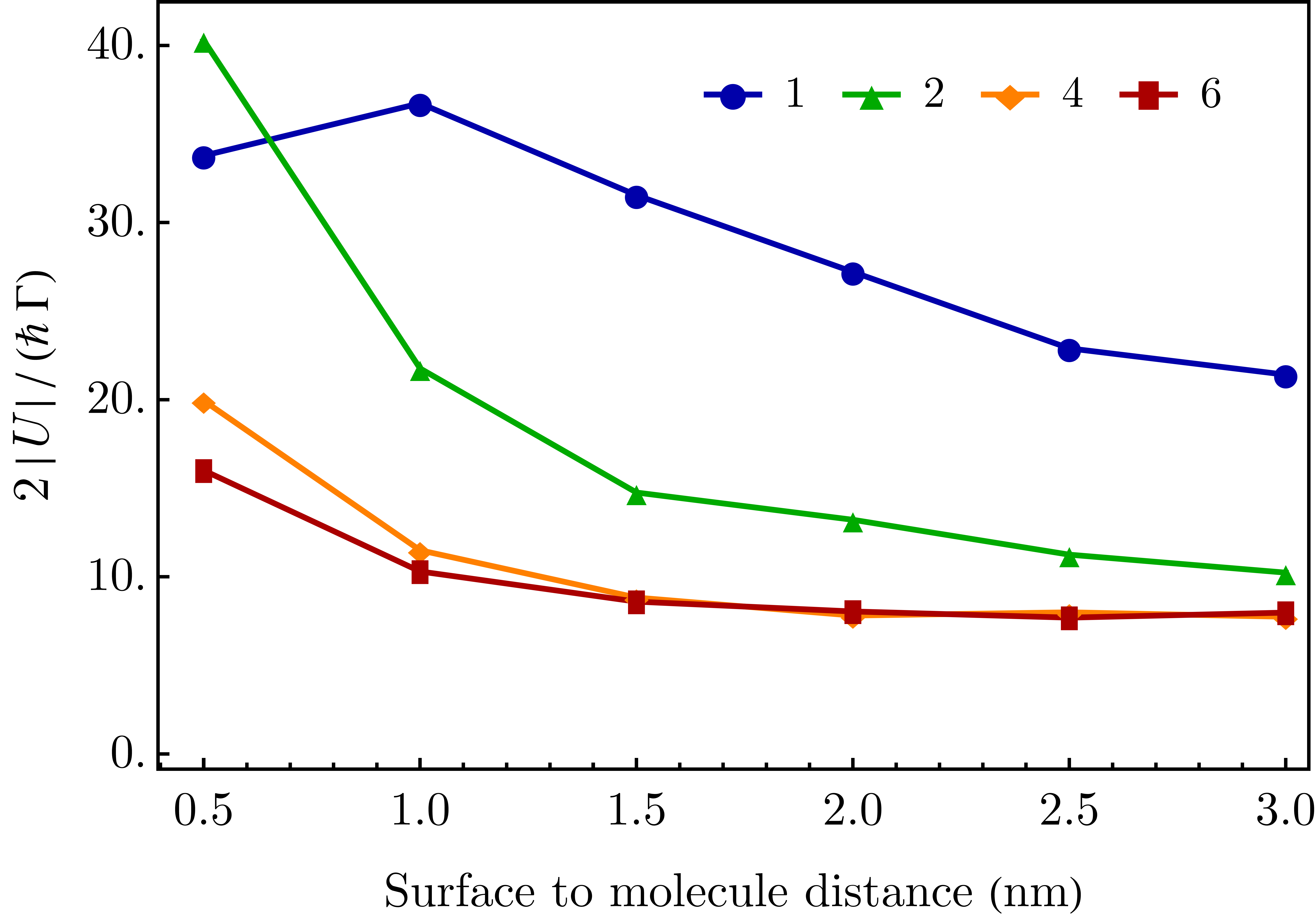
Figures 2-7 show the coupling strength , the lifetime broadening and the coupling-broadening ratio (CBR) calculated at the resonance frequency of the free molecule for several geometries. A value larger than of the CBR indicates strong coupling by the criterion (14). For definiteness, in the calculation shown below, the molecular transition dipole is taken to be D. However the free molecule transition frequency is taken to be equal to the dipolar plasmon frequency of the metal corresponding to geometry under consideration. For example, when considering a molecular dipole near small gold and silver spheres, the molecular frequencies are taken equal to corresponding dipolar plasmon frequencies, eV and eV for gold and silver spheres respectively. However, the coupling strength, which is calculated by fitting the calculated to the plasmon peak is, by this definition, frequency independent.
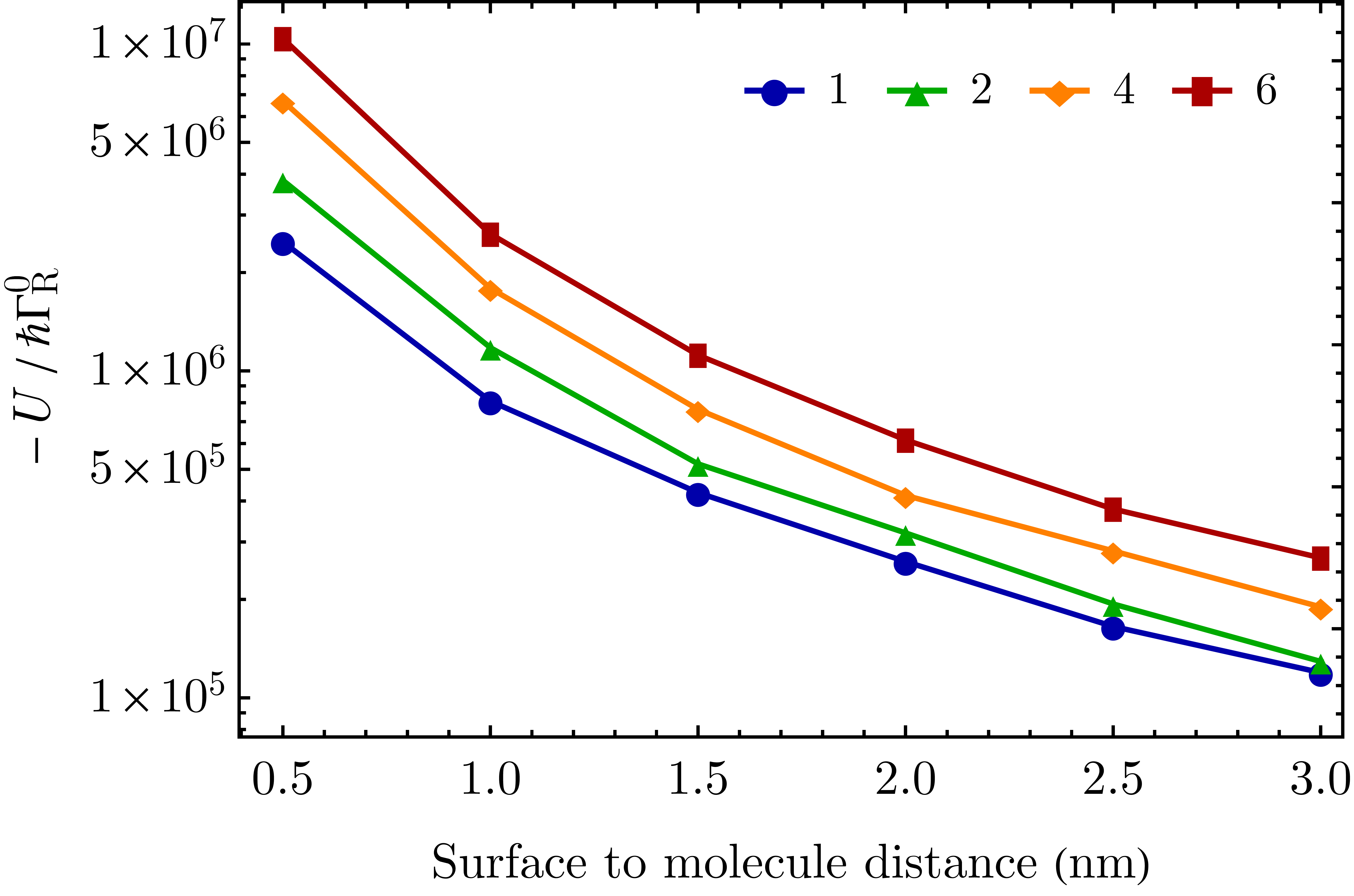
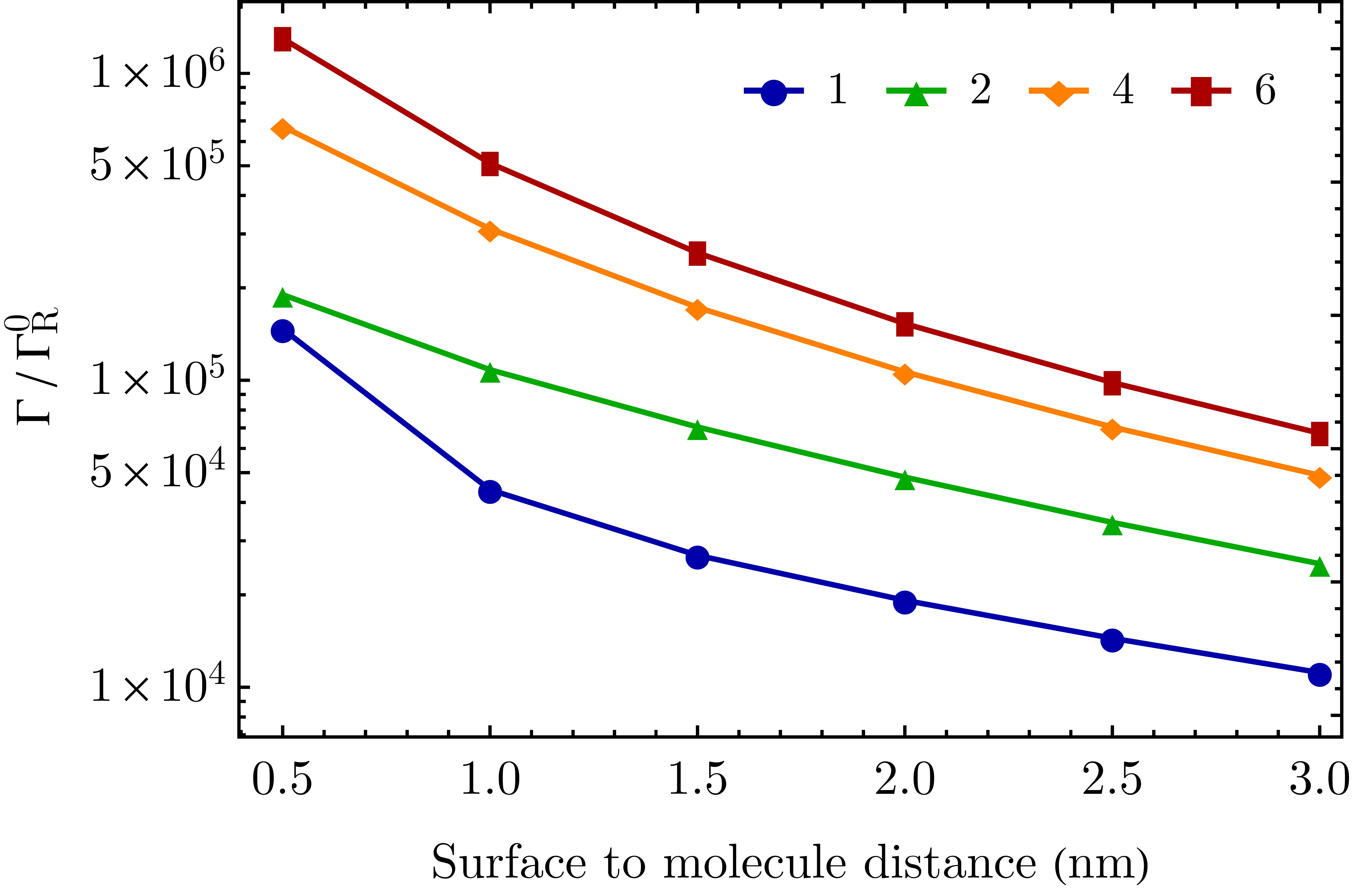
The calculations of the radiative and metal-induced nonradiative contributions to (Eqs. (11), (12)) have been extensively discussed before111, and typical results showing the dependence of these rates on the molecular orientation and its distance from the metal structure, and on the size and shape of this structure are shown in the SI (Section LABEL:SI_results_additional). We emphasize again, that the only contributions to the linewidth that are considered here are the lifetime (radiative and non-radiative) of the free molecule, and the metal induced modifications of these lifetimes, and that in the calculations reported below we have assumed that a free molecule has an intrinsic non-radiative relaxation rate that is equal to its radiative rate, implying that the emission yield of a free molecule is . Note that if the intrinsic non-radiative relaxation rate of the free molecule is disregarded, the remaining contributions to the linewidth are proportional to the square of the molecular transition dipole , whereas the coupling (Eq. (5)) is linear in this parameter. Consequently, and perhaps counter-intuitively, the CBR satisfies and decreases with increasing molecular transition dipole. The relaxation rates (and magnitude of coupling) are normalized by the radiative relaxation rate of a free molecule which is calculated from at the respective molecular frequency.
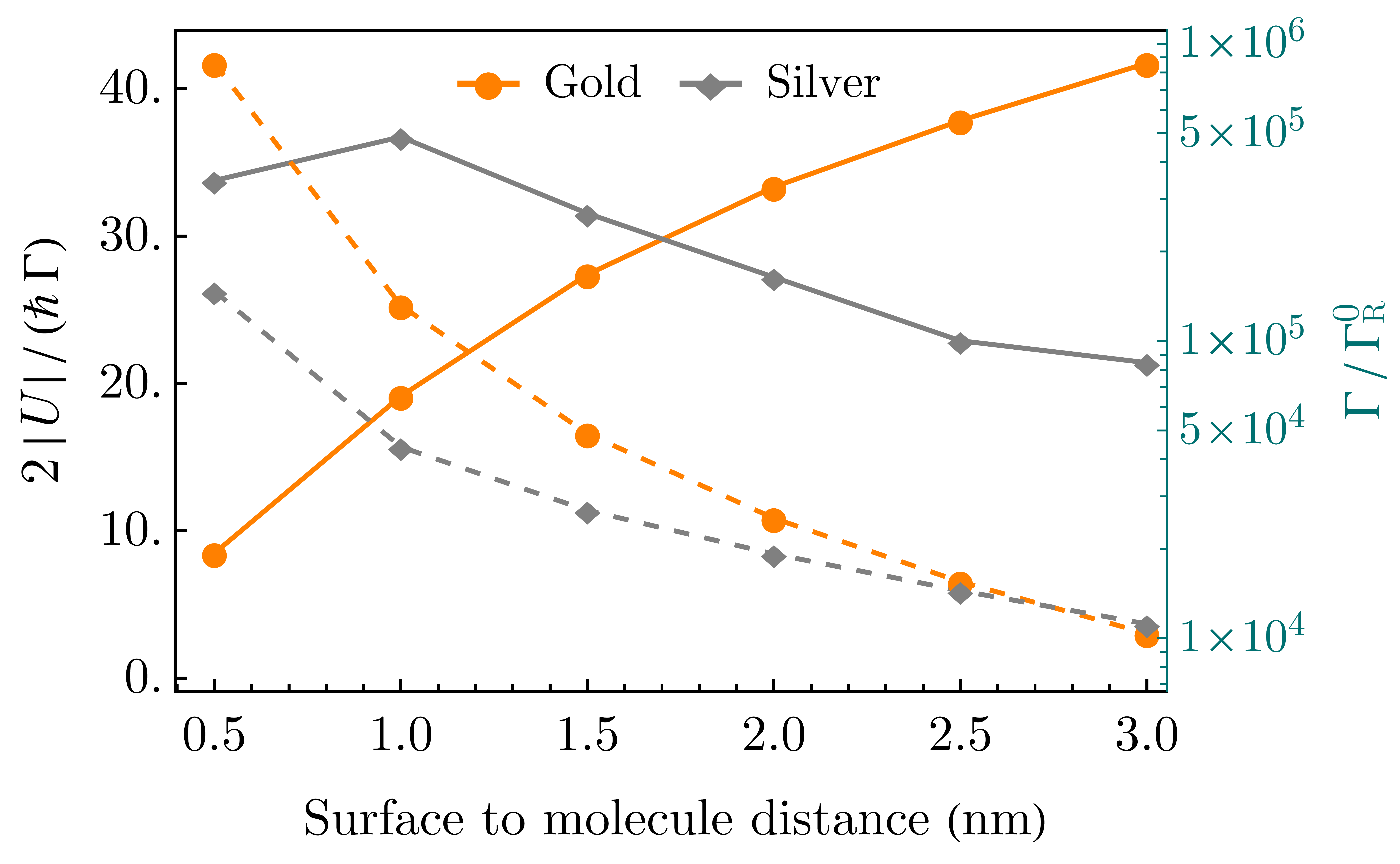

Figure 2 depicts the CBR for a molecule near spherical gold and silver particles of radius nm, in normal and parallel orientations relative to the sphere surface, as a function of the molecule-surface distance. Also shown is the combined relaxation rate . It is seen that “strong coupling” as defined by the criterion, is not necessarily associated with close proximity. Both and and go quickly to zero when the molecule-surface distance increases, however their ratio varies relatively slowly, and remains larger than in all the distance range studied. It is interesting to note that in both the normal and parallel configurations this ratio goes through maximum for silver and decreases beyond a distance nm while for gold it rises monotonically with increasing distance. The metal induced nonradiative relaxation, being the major contribution to the combined relaxation rates, is very large when close to the nanoparticle surface. As a consequence, for silver there is an optimum distance of the molecule from the surface where the CBR is maximum. For gold, on the other hand, because the extent of the effect of nonradiative decay rate is even more, for the distance considered, CBR is larger as the molecule is distant from the surface. Qualitatively for both perpendicular and parallel orientation, these observations are common.
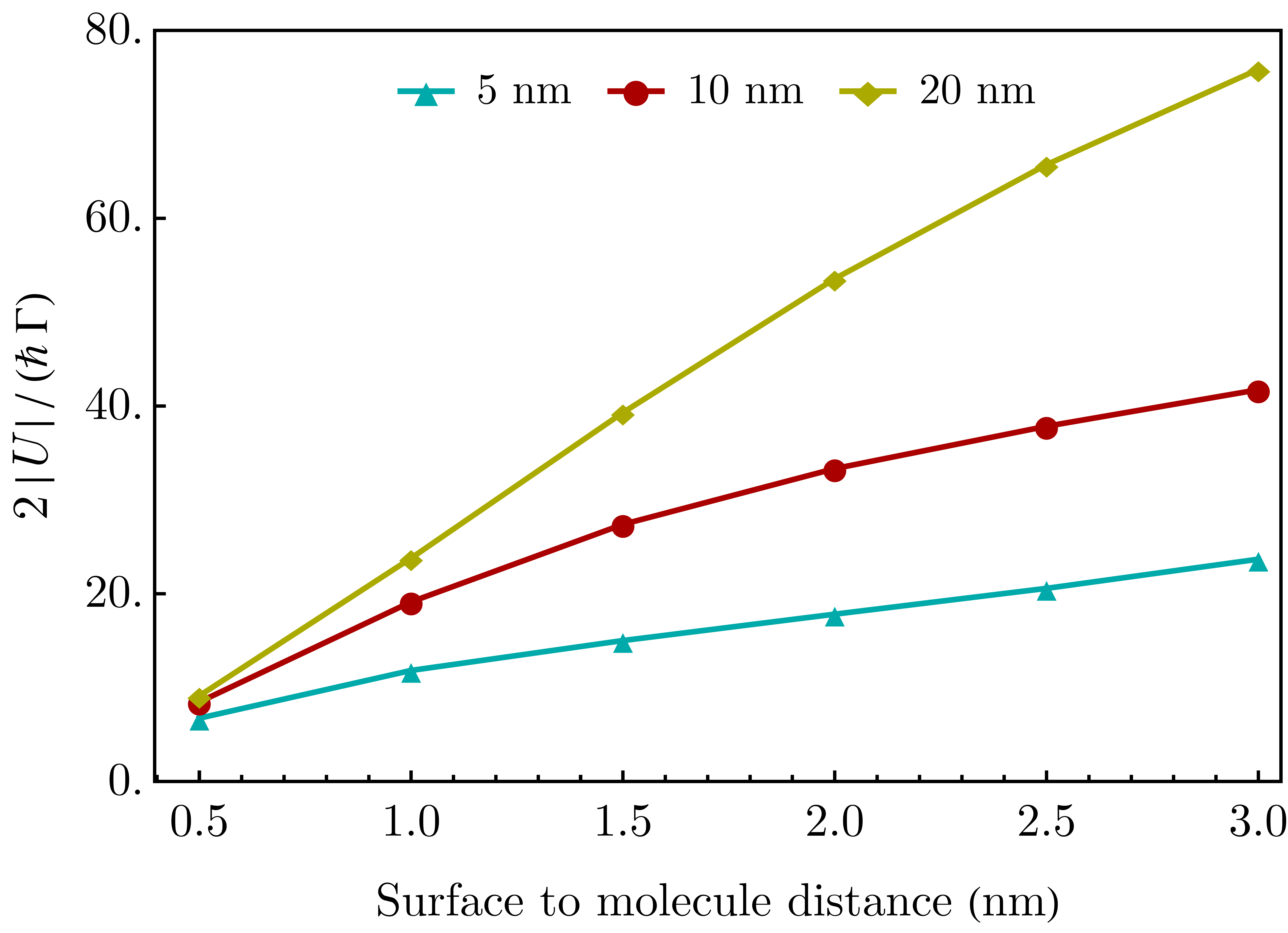
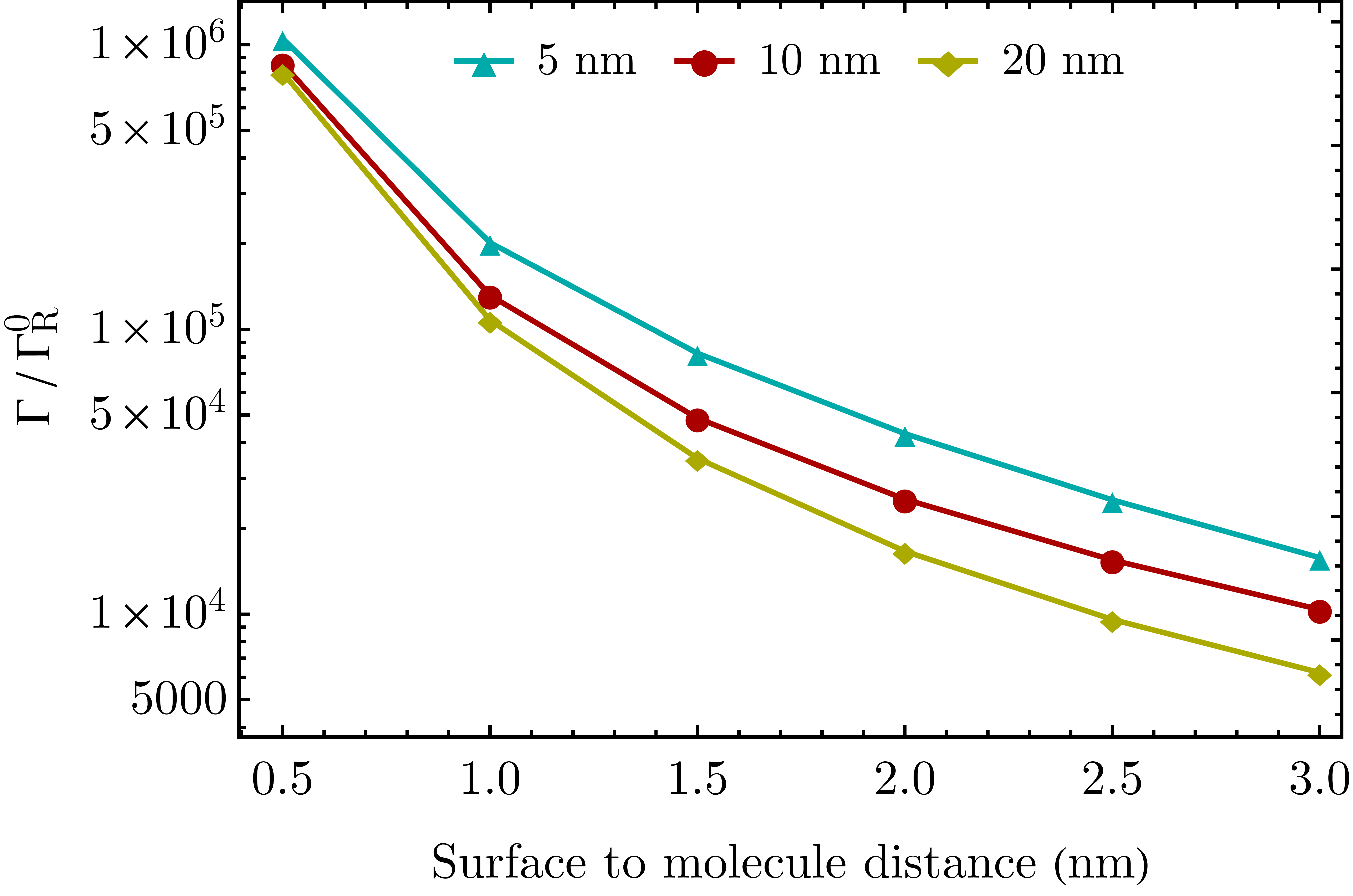
These estimates of strong coupling show considerable dependence on the size and shape of the dielectric nanostructure. Figure 3 shows the CBR parameter as well as the lifetime broadening plotted against the molecule-(spherical gold) nanoparticle surface distance for different particle sizes in the perpendicular dipole orientation, while Figures 4 and 5 show similar results for different particle shapes by considering metal spheroids of constant volume ( volume of a sphere of radius nm) and different aspect ratios when the molecule is positioned on the long axis with a normal orientation relative to the nanoparticle surface.
In the latter figures (4-5) we show the magnitude of coupling (panel b in these figures) and total relaxation rates (panel c in the same figures). More details on the radiative and non-radiative contributions to for a molecular dipole positioned near gold and silver nanospheroids, are provided in the SI, Section LABEL:subsec:spheroid_perp_results_gold_silver.
Figures 6 and 7 show similar quantities for a molecular dipole positioned between two metal spheres. The (point) dipole is placed on the axis connecting the sphere centers (called the intersphere axis) and oriented parallel (and normal) to this axis. The molecular transition frequency is taken to be in resonance with the stronger plasmon peak associated with the corresponding configuration (see Figure LABEL:fig:SI_rad_decay_bisph_uni_field_gold_silver_para_perp for the optical response of gold and silver bispherical structures).
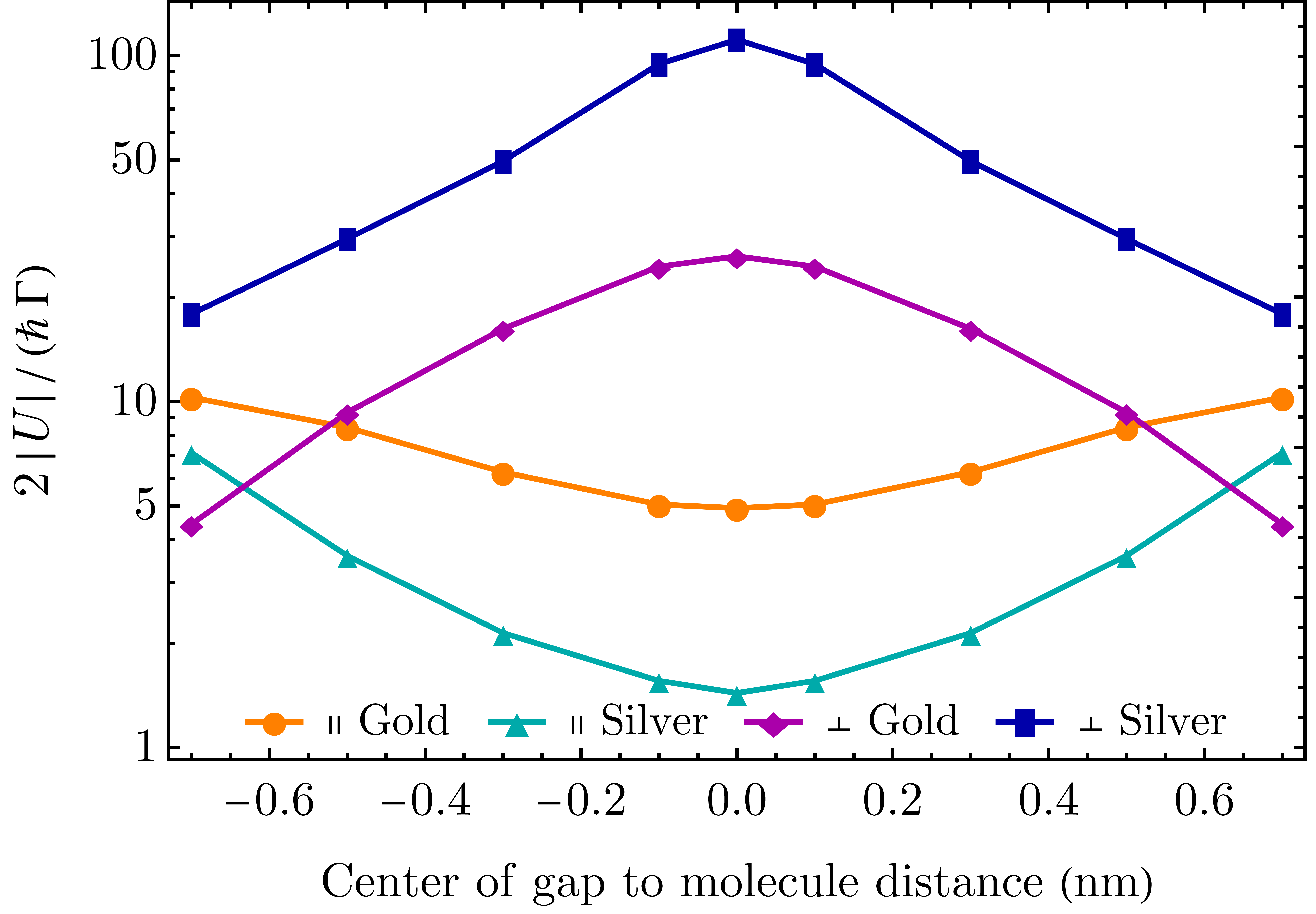
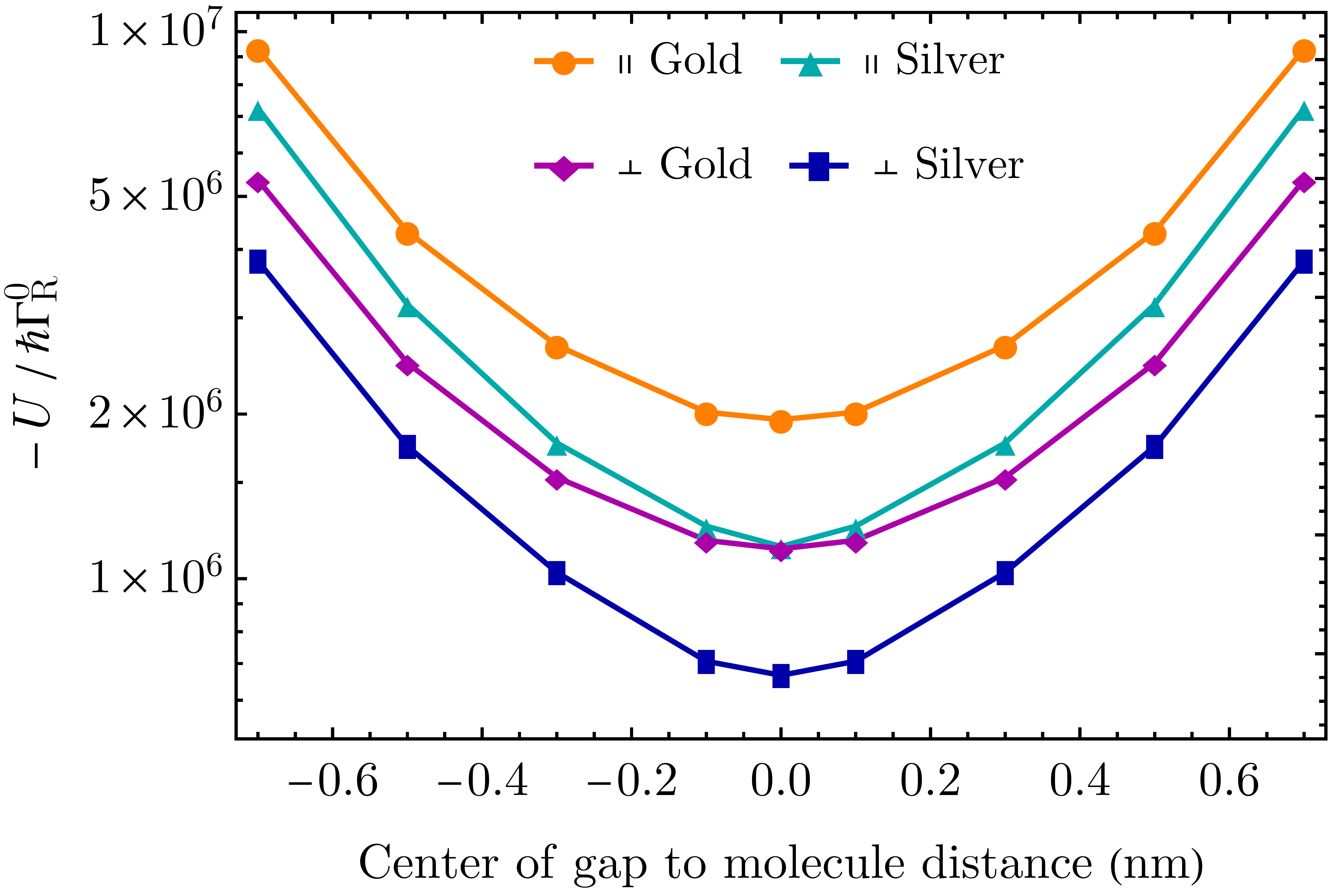
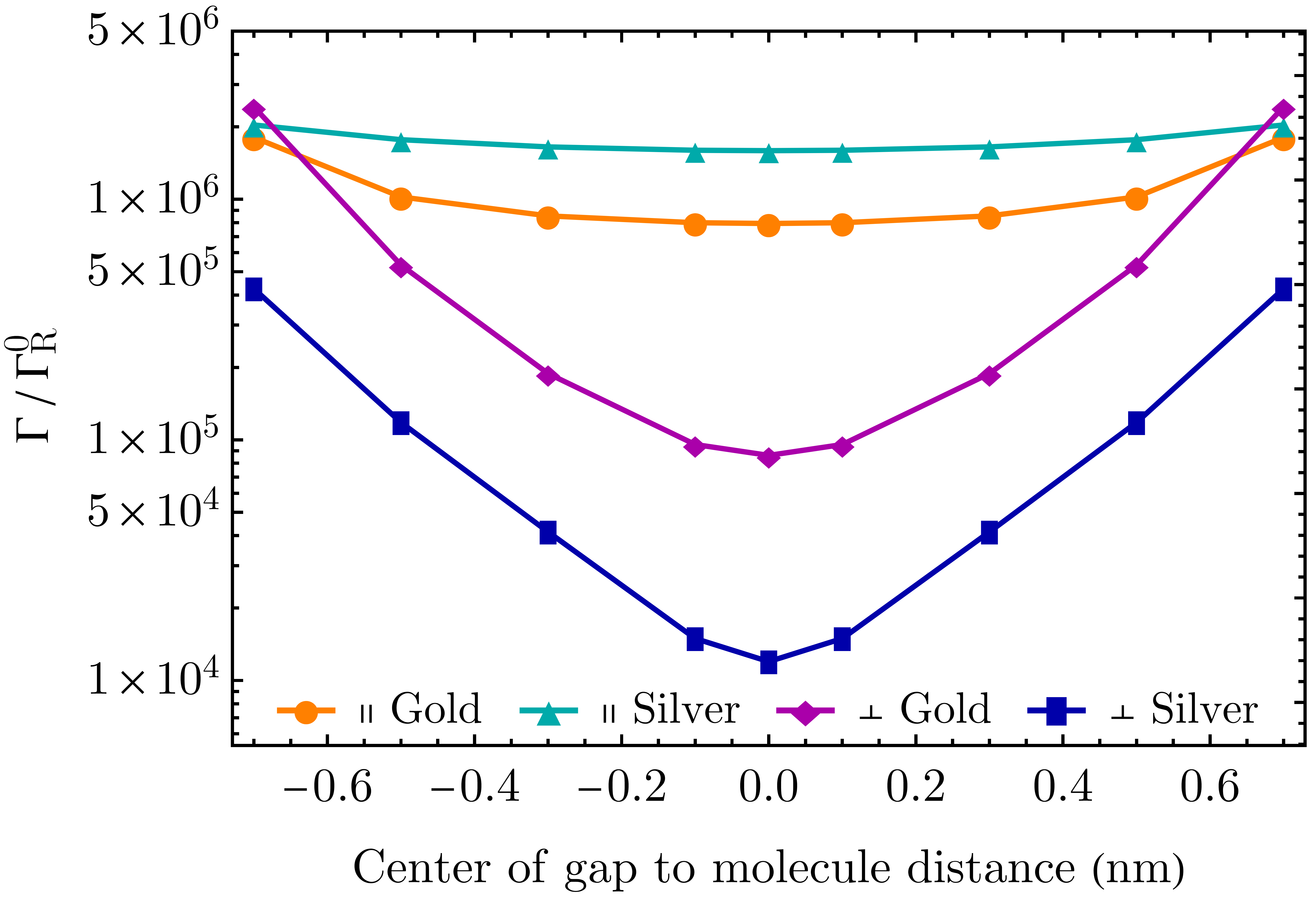
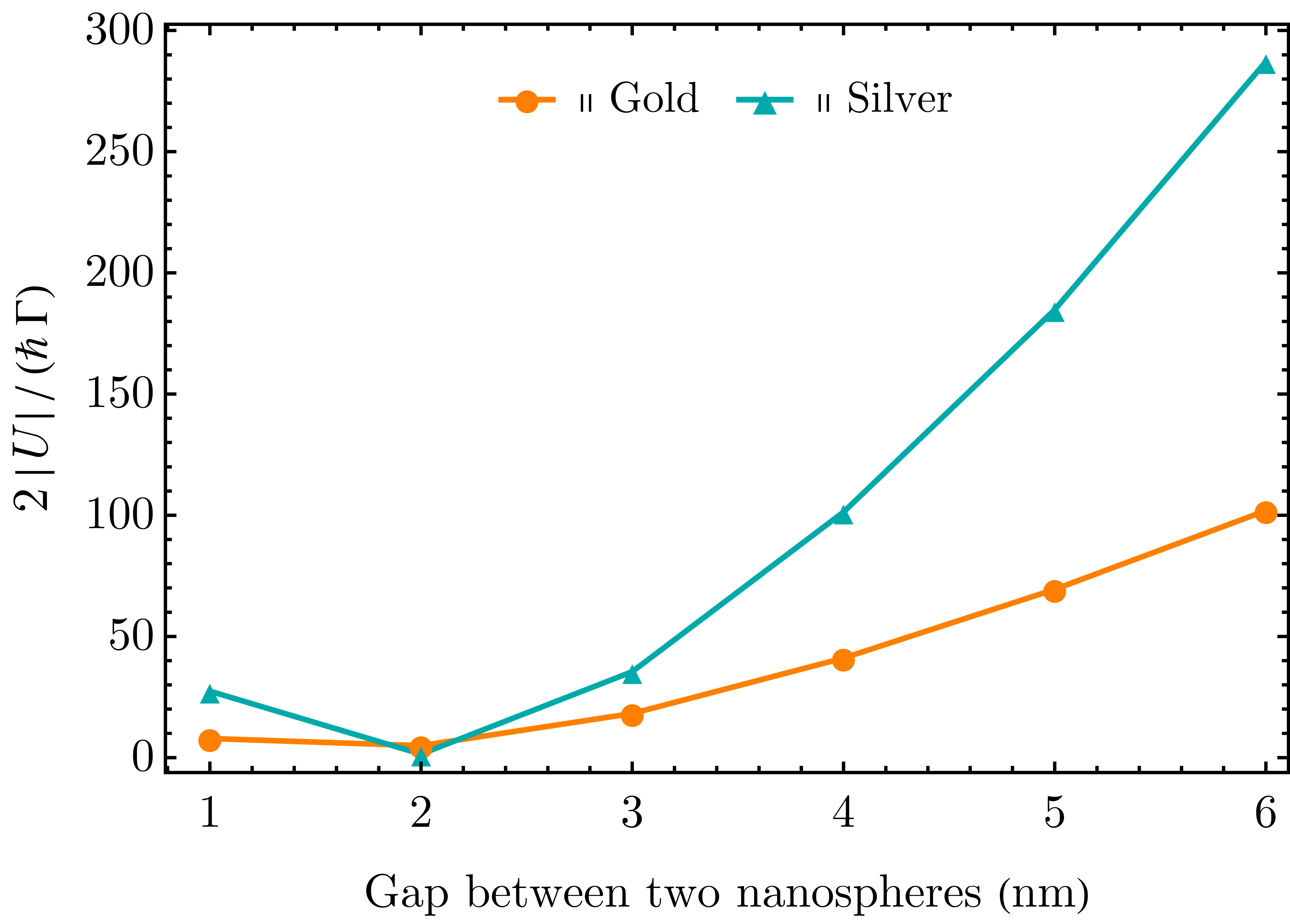
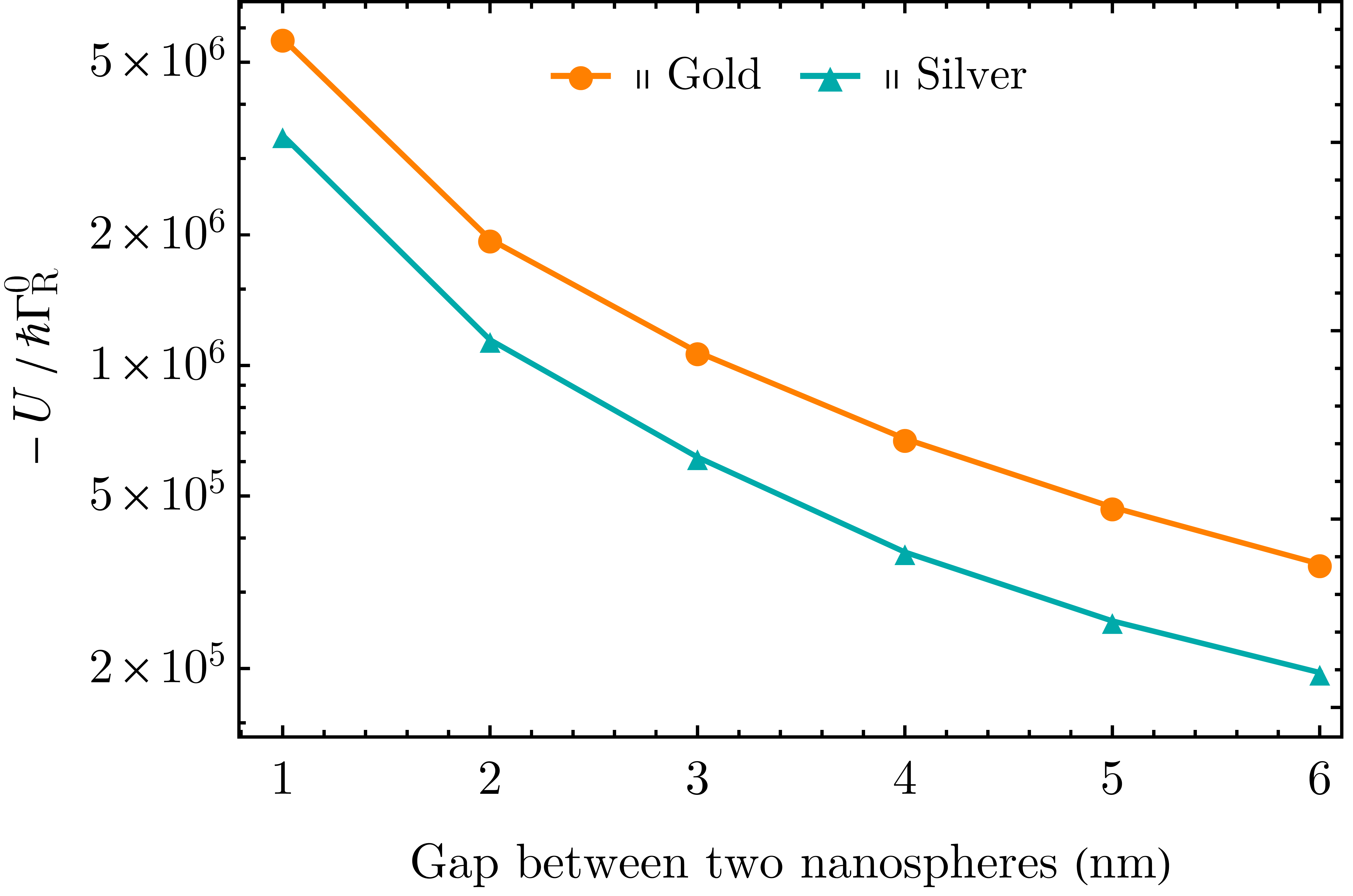
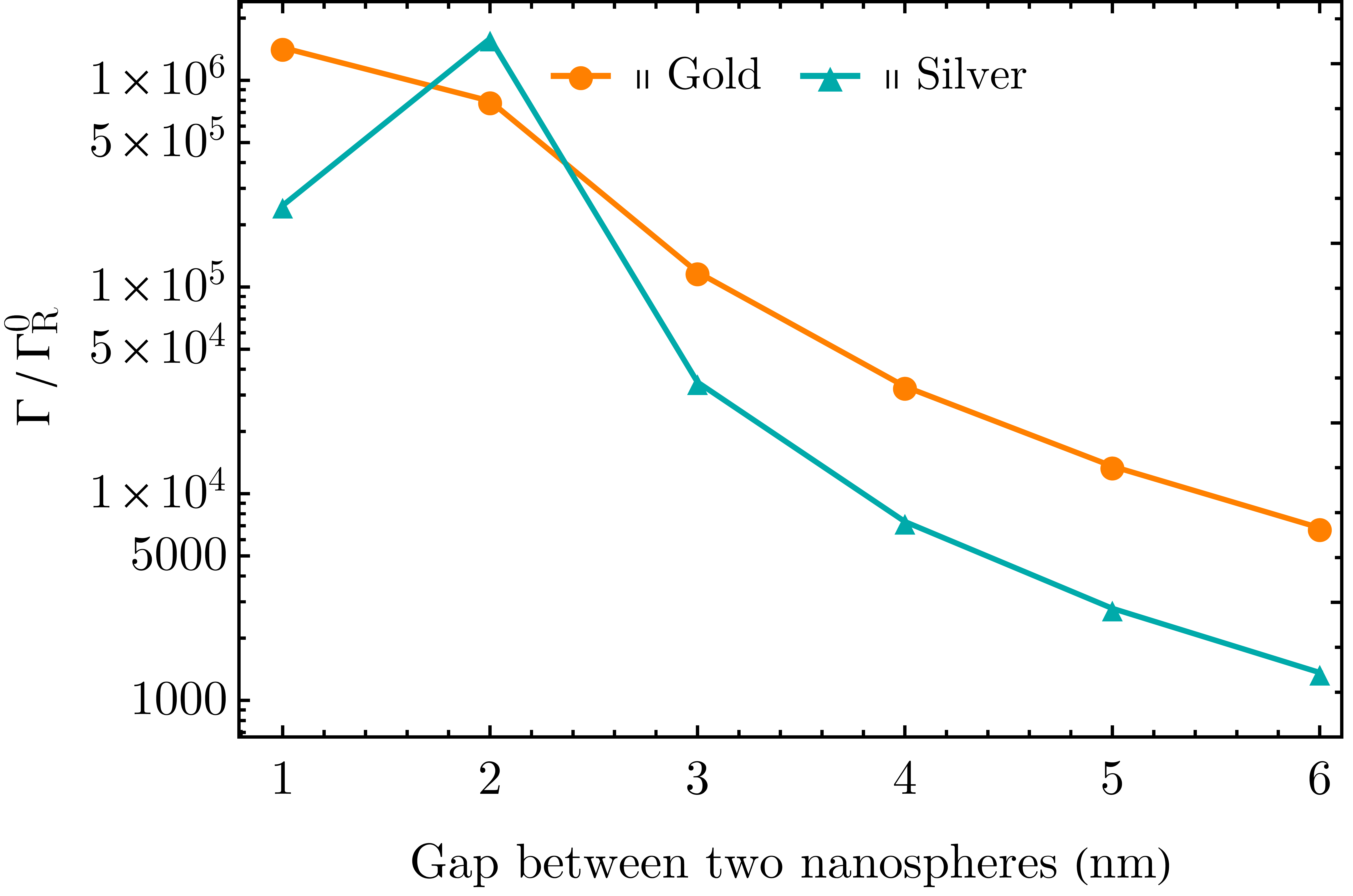
Next, we consider the effect of the gap size for the likes of the configurations shown in Figure 6, i.e., molecule in the gap in between nanosphere dimers, specifically for the parallel molecular orientation relative to the intersphere axis. In particular, in Figure 7, the CBR parameter, the coupling magnitude, and the combined relaxation rate are displayed for both gold and silver nanoparticle dimers. In all calculations, the molecule is assumed to be positioned in the middle of the gap. To note, the molecular frequency is taken to be in resonance with the higher plasmon peak for the configuration with two nm metal nanoparticles with a nm gap. For this reason, the calculated combined relaxation rate in Figure 7c shows a clear maximum for nm gap size for silver. This also explains the slight deviation from the trend for gold.
The configuration considered here, with the molecule positioned in the space between two nanoparticles, is often referred to as a plasmonic cavity. The effective cavity volume can be determined from the calculated using Eq. (9). Obviously this “effective volume” can be defined also for configurations that cannot be perceived as cavities, such as used in Figures 2-5 (dipole-sphere/spheroid systems), and it depends on the particular geometry considered, including the dipole position and orientation. It is therefore of limited value for molecules interacting with plasmonic structures, but because of its prominence in many discussions we show several examples of this parameter in the SI (Figures LABEL:fig:SI_eff_vol_sph_sphd_perp_gold_silver_par_vol-LABEL:fig:SI_eff_vol_bisph_para_perp_gold_silver_gap_cube).
(A) The interplay between coupling and broadening that determine “strong coupling” according to Eq. 14 depends strongly on geometry. While this fact is widely appreciated, the particulars of these dependence are sometimes surprising as exemplified in points (C) and (D) below.
(B) In the plasmonic structures studied, the intrinsic coupling-broadening ratio (CBR) parameter is usually large, and by itself satisfies the strong coupling criterion. Here, “intrinsic” implies that we consider only spectral broadening effects that reflect (a) the molecular radiative lifetime and fluorescence yield associated with the transition considered and (b) the effect of the electromagnetic molecule-metal interaction on the molecule radiative and non-radiative relaxation rates. This intrinsic broadening disregards other sources of spectral broadening such as congestion of many overlapping transitions and environmentally induced thermal relaxation.
(C) While both the molecule-plasmon coupling and the intrinsic molecular lifetime broadening (by “intrinsic” we mean broadening associated only with the isolated molecule, the plasmonic nanostructure and their interaction) strongly decrease with increasing molecule-metal surface distance444For the metal-molecule distances considered in our calculations, the intrinsic lifetime broadening is dominated by the molecule-metal interaction., the CBR remains large and the corresponding criterion for “strong coupling” persists at large distances. This observation by itself is meaningless as other sources of broadening as well as limited resolution will usually mask the Rabi structure. This does indicates, however, that if other sources of broadening and relaxation are eliminated (such as with zero-phonon transitions at cryogenic temperatures), signature of strong coupling would be observed in single molecule plasmonic cavities, in agreement with a recent observation103.
(D) Because of the interplay between local electromagnetic coupling and particle induced relaxation, “hotspots” characterized by a large enhancement of the local electromagnetic fields do not necessarily stand out with regard to the CBR. To illustrate this consider the perpendicular and parallel orientation of a molecular dipole of D transition dipole moment positioned nm apart from a silver nanosphere of nm radius. For the perpendicular orientation, the coupling strength is larger in magnitude than the parallel orientation: (perpendicular) and (parallel). However, the associated nonradiative relaxation rate is also larger for perpendicular orientation: (perpendicular) and (parallel) (the radiative decay rate is smaller than these number by order of magnitude at this small distance from metal surface, so does not have significant contribution to the CBR). As a result, the value of CBR for parallel orientation is more than twice the value for perpendicular case (, ).
Finally, consider the self-consistent treatment of Eq. (19). We reiterate that the results shown in Figures 2-7 are based on a calculation of , , computed in a model in which the molecular dipole drives the system and do not reflect the actual lineshape. In particular, such a calculation does not account for spectral lineshifts induced by the proximity of the molecule to the metal nanostructure and for the relative peaks intensities, even if Rabi splitting occurs. Therefore, the results shown in Figures 2-7 only indicate the fulfillment of the strong coupling criterion (Eq. (14)) but not the observability of an actual Rabi splitting. Figures 8-9 show results based on the self-consistent calculation, Eqs. (15)-(19), which yields the actual absorption lineshape for the process in which a dipolar emitter, coupled to the metal nanostructure, is driven by an incident external field.
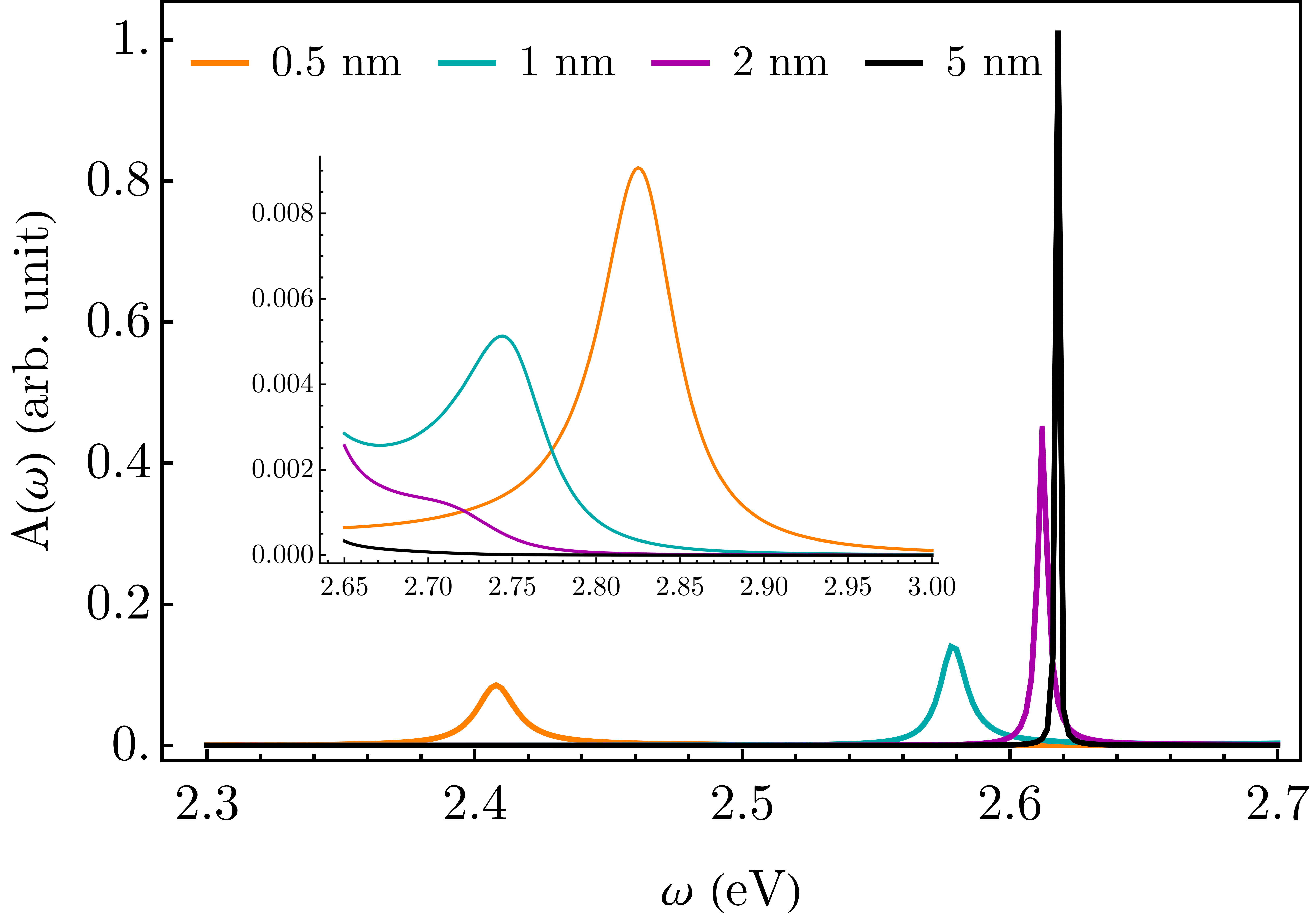
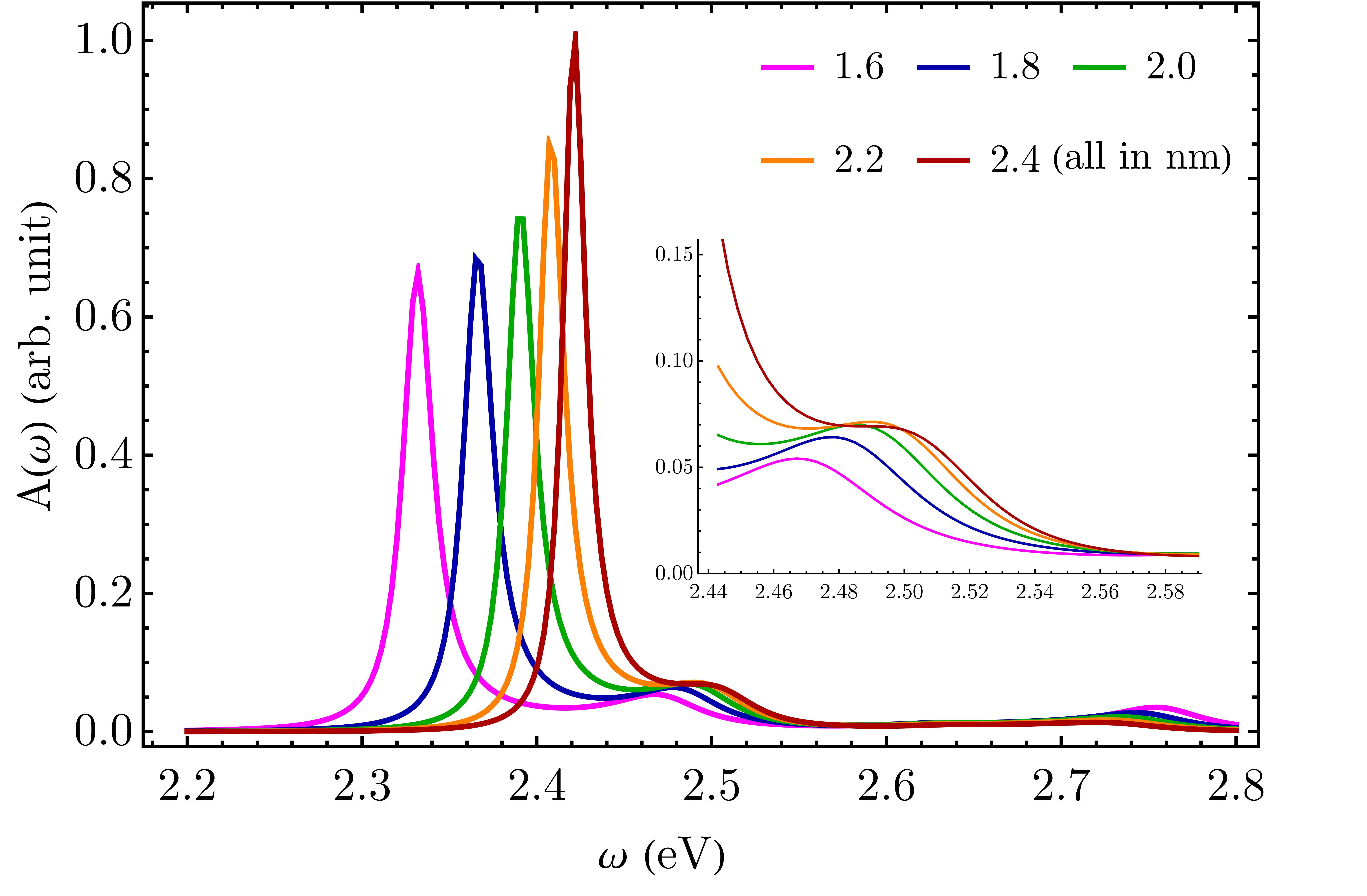
Figure 8 shows this lineshape, calculated for a dipole emitter near a spherical gold nanosphere (radius nm), oriented perpendicular to the sphere surface and parallel to the incident field. The transition frequency is taken eV, in resonance with the dipolar plasmon frequency of the gold nanosphere. As before, the relaxation rate of the free molecule is taken to be twice the radiative relaxation rate, corresponding to an emission yield of for the free molecule. Figure 8a depicts the absorption lineshape for a dipole situated at nm away from the sphere surface for different values of the molecular transition dipole moment in the range D. Figure 8b displays the absorption lineshape for an emitter with transition dipole moment D placed at different distances ( nm) from the sphere surface. Similar results for silver are shown in Figure LABEL:subsec:SI_self_cons_silver. Figure 9 shows similar results for a molecular dipole in the middle of the gap between two identical gold spheres (radii nm) oriented parallel to the intersphere axis, where the incident electric field is parallel to this axis as well. For a bispherical structure, the plasmonic response for an incident plane field is characterized by a double-peak structure which results from the interacting dipolar plasmonic responses of the individual spheres and depends on the inter-sphere distance. The emitter transition frequency is taken to be in resonance with the lower frequency and more intense one of these peaks (see Figure LABEL:fig:SI_rad_decay_bisph_uni_field_gold_para_perp). The results shown in Figure 9a are for an intersphere gap size nm and different values of the molecular transition dipole moment, while Figure 9b shows the lineshapes for a transition dipole D at varying gap sizes.
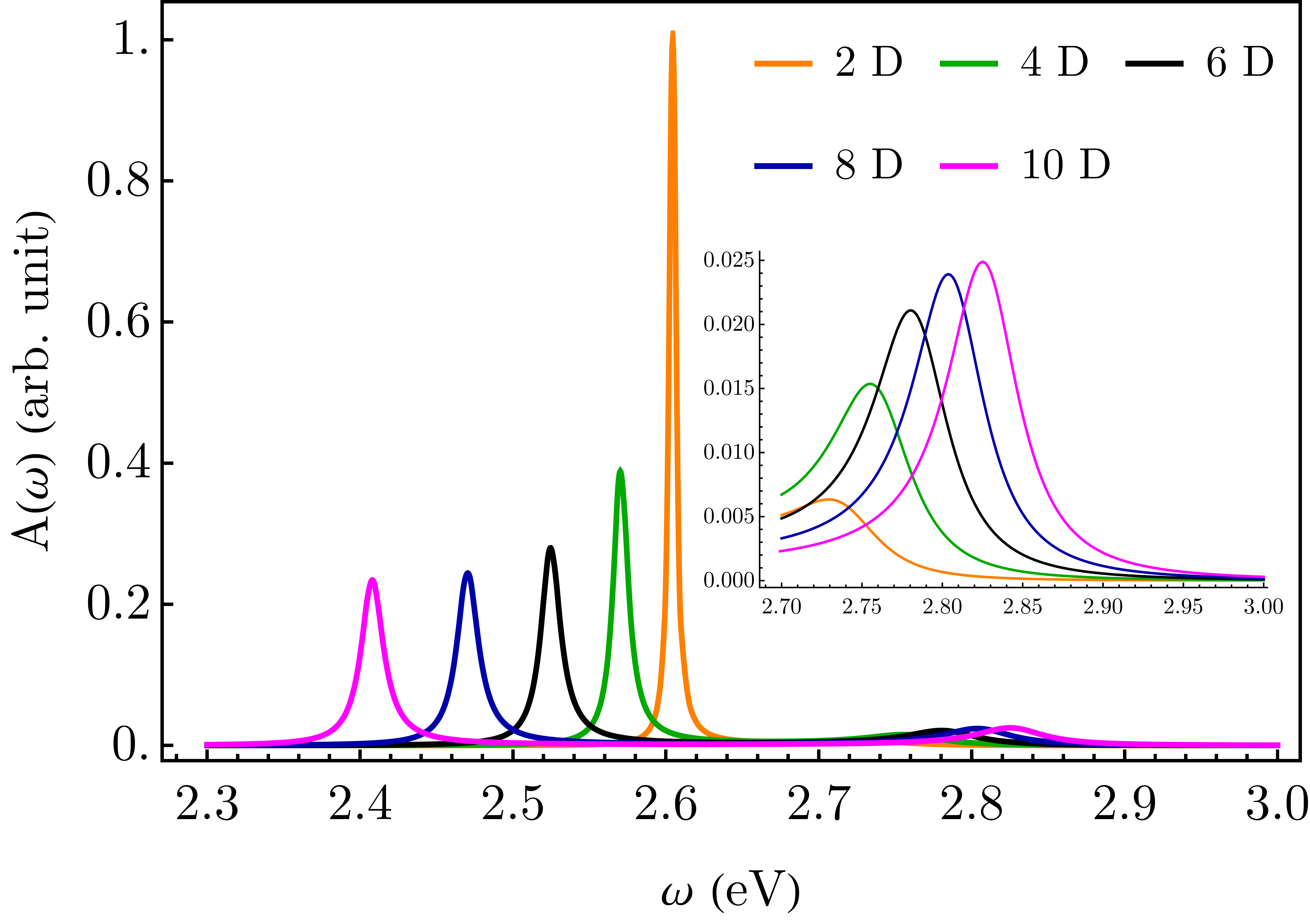
Consider first the case of an emitter near a spherical gold nanoparticle (Figure 8). Keeping in mind that in this model calculation the incident field is taken to be coupled only to the emitter, it is the emitter absorption peak that is seen for weak coupling (orange line in panel (a) and black line in panel (b)). The main effect of strong coupling upon increasing the molecular transition dipole is seen to be a strong red shift of the molecule-dominated peak. The particle’s optical signature, resulting the molecule-particle interaction is seen on the high energy side of the spectrum, is small, leading us to conclude that a pronounced Rabi splitting is not expected in this configuration. In contrast, the optical response of a system comprising a molecule positioned between two gold spheres does show a clear evidence of such splitting as seen in Figure 9. This observation is consistent with that of Ref. (121) that for a dimer-like structure of gold nanoparticles, a strong coupling situation is likely to result when the interparticle gap is less than nm.
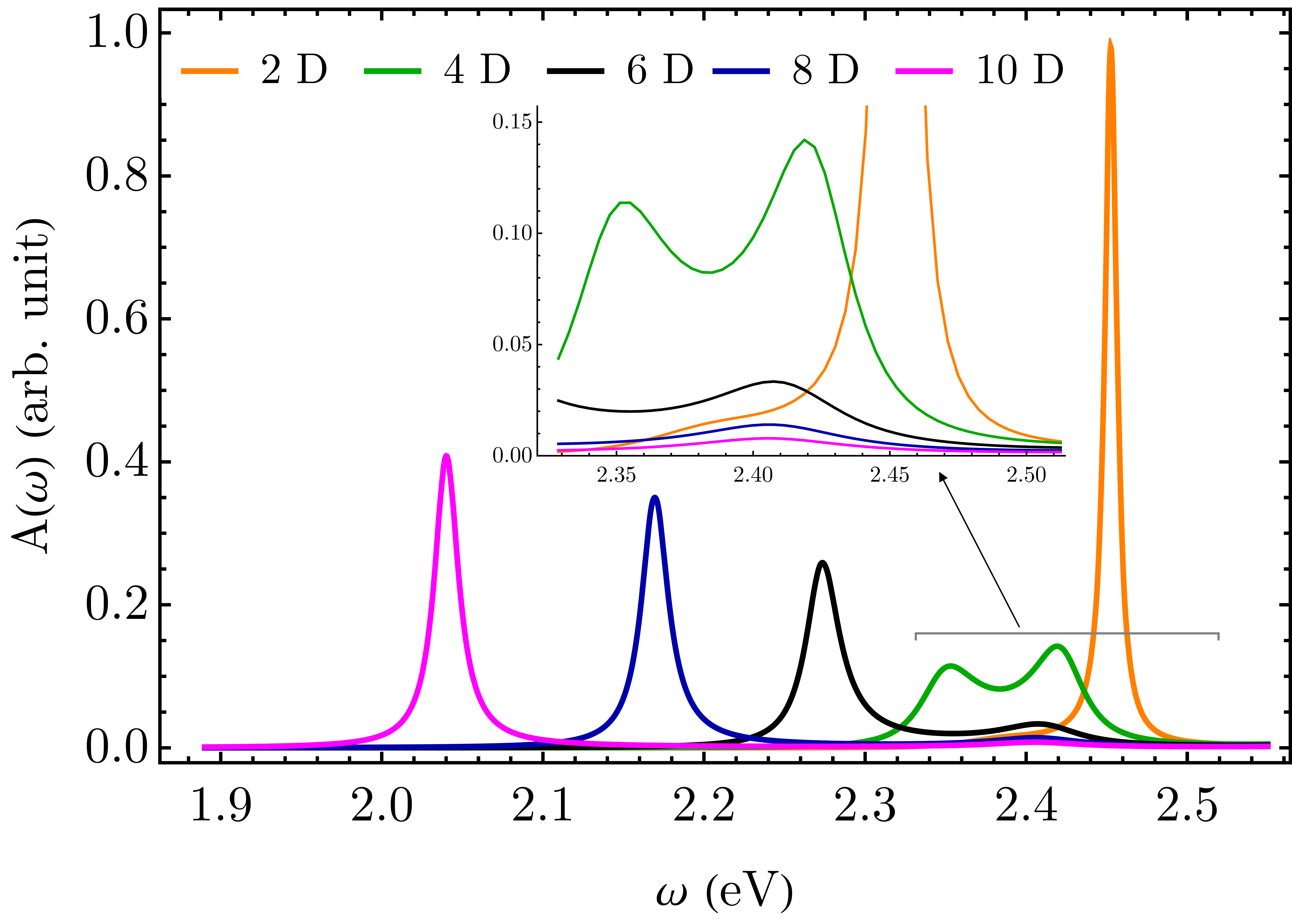
While “strong coupling” between a single molecule and a metal-plasmon excitation, manifested in the split-peak structure of the absorption lineshape, is seen in the calculated spectra in Figure 9, these results also indicate that the simpler model calculation of the CBR shown in Figures 2-7 is not by itself sufficient to predict the observability of this spectral feature. The CBR, Eq. (14), does provide an estimate of the relationship between the molecule-metal nanostructure coupling and the associated broadening, but does not necessarily lead to an observed Rabi splitting which is usually assumed to be a prime manifestation of such strong coupling. We have identified the strong spectral shift, another manifestation of this coupling, as the main reason for this apparent discrepancy. This may also lead to apparent counter-intuitive observations: for example, comparing the lineshapes in Figure 9a, a clear Rabi splitting is seen for an emitter with transition dipole D, while a single peak is seen for a D emitter. In the stronger coupling case of an emitter with transition dipole moment D, a larger Rabi splitting is indicated by the calculation, but the dominance of the lower energy peak may appear as a single peak in a realistic observations. It should be noted that this shift will also affect the distance dependence of the radiative and radiationless relaxation rates of a molecule approaching a metal surface and may potentially play a role in the observed “quenching of quench”, where the emission yield of an emission appears to increase, rather than decrease, as the molecule-surface distance decreases (see Ref. (101 ) and references therein). We emphasize however that no such trend in the emission yield , Eq. (13), was seen in our calculations.
5 Conclusions
Strong radiation matter coupling is often characterized in the literature as a relative concept, by comparing the absolute magnitudes of the coupling and the broadening , and the strong coupling criterion , an indication that Rabi splitting may be observed when the molecular and plasmon optical transition come into resonance, is often used. While usually observed when an optical mode interacts with many molecules, it has been noted, as outlined in the introduction, that this criterion can be satisfied even for single molecules interacting with metallic plasmonic structures. A necessary condition for observing this phenomenon in such setting is that the the coupling-broadening ratio (CBR), , satisfies the strong coupling criterion when and are derived from the interaction between a single molecular transition when the molecule interacts only with the plasmonic structure, in the absence of other sources of broadening. Using simple analytically solvable model structures, representing the molecule as a point dipole and treating radiation-matter coupling in the long wavelength approximation whereas all distances are assumed small relative to the radiation wavelength, we have found that this condition is easily satisfied. Surprisingly, we observe that this remains true when the molecule-metal distance increases so that the absolute coupling itself becomes small. This suggest that Rabi splitting can be observed in systems involving a single molecule interacting with small metal particles if other sources of broadening can be suppressed, as was recently observed using the low temperature molecular zero-phonon transition103.
It should be kept in mind that even if the strong coupling criterion, Eq. (14), is satisfied, such observation by itself is not an indication of strong radiation-matter coupling when this coupling is compared to other molecular energetic parameters. Furthermore, by considering the results of a self-consistent calculation that addresses directly the absorption lineshape in a system of interacting a molecule and the plasmonic structure, we find that the intrinsic CBR satisfying the strong coupling criterion does not guarantee the observation of Rabi splitting in the absorption spectrum because the coupling induced spectral shift together with the strong frequency dependence of the imaginary part of plasmonic response can result in a spectrum dominated by a single, albeit shifted, molecular peak. {acknowledgement} M.S. acknowledges the financial support by the Air Force Office of Scientific Research under Grant No. FA9550-19-1-0009. A.N. acknowledges the support of the U.S. Department of Energy, Office of Science, Basic Energy Sciences, Chemical Sciences, Geosciences, and Biosciences Division.
References
- Benz et al. 2014 Benz, F.; Tserkezis, C.; Herrmann, L. O.; De Nijs, B.; Sanders, A.; Sigle, D. O.; Pukenas, L.; Evans, S. D.; Aizpurua, J.; Baumberg, J. J. Nanooptics of molecular-shunted plasmonic nanojunctions. Nano letters 2014, 15, 669–674
- Lin et al. 2015 Lin, L.; Zapata, M.; Xiong, M.; Liu, Z.; Wang, S.; Xu, H.; Borisov, A. G.; Gu, H.; Nordlander, P.; Aizpurua, J., et al. Nanooptics of plasmonic nanomatryoshkas: shrinking the size of a core–shell junction to subnanometer. Nano letters 2015, 15, 6419–6428
- Karnetzky et al. 2018 Karnetzky, C.; Zimmermann, P.; Trummer, C.; Duque Sierra, C.; Wörle, M.; Kienberger, R.; Holleitner, A. Towards femtosecond on-chip electronics based on plasmonic hot electron nano-emitters. Nature Communications 2018, 9, 2471
- Kamp et al. 2020 Kamp, M.; Nijs, B. d.; Kongsuwan, N.; Saba, M.; Chikkaraddy, R.; Readman, C. A.; Deacon, W. M.; Griffiths, J.; Barrow, S. J.; Ojambati, O. S.; Wright, D.; Huang, J.; Hess, O.; Scherman, O. A.; Baumberg, J. J. Cascaded nanooptics to probe microsecond atomic-scale phenomena. Proceedings of the National Academy of Sciences 2020, 117, 14819–14826, Publisher: National Academy of Sciences Section: Physical Sciences
- Sekhon and Verma 2011 Sekhon, J. S.; Verma, S. Optimal dimensions of gold nanorod for plasmonic nanosensors. Plasmonics 2011, 6, 163–169
- Jeong et al. 2016 Jeong, H.-H.; Mark, A. G.; Alarcón-Correa, M.; Kim, I.; Oswald, P.; Lee, T.-C.; Fischer, P. Dispersion and shape engineered plasmonic nanosensors. Nature communications 2016, 7, 11331
- Anker et al. 2010 Anker, J. N.; Hall, W. P.; Lyandres, O.; Shah, N. C.; Zhao, J.; Van Duyne, R. P. Nanoscience and Technology: A Collection of Reviews from Nature Journals; World Scientific, 2010; pp 308–319
- Choi and Choi 2011 Choi, I.; Choi, Y. Plasmonic nanosensors: review and prospect. IEEE Journal of Selected Topics in Quantum Electronics 2011, 18, 1110–1121
- Verschueren et al. 2019 Verschueren, D.; Shi, X.; Dekker, C. Nano-Optical Tweezing of Single Proteins in Plasmonic Nanopores. Small Methods 2019, 3, 1800465
- de Nijs et al. 2017 de Nijs, B.; Benz, F.; Barrow, S. J.; Sigle, D. O.; Chikkaraddy, R.; Palma, A.; Carnegie, C.; Kamp, M.; Sundararaman, R.; Narang, P., et al. Plasmonic tunnel junctions for single-molecule redox chemistry. Nature communications 2017, 8, 994
- Tesema et al. 2019 Tesema, T. E.; Kafle, B.; Habteyes, T. G. Plasmon-Driven Reaction Mechanisms: Hot Electron Transfer versus Plasmon-Pumped Adsorbate Excitation. The Journal of Physical Chemistry C 2019, 123, 8469–8483
- Shaik et al. 2018 Shaik, F.; Peer, I.; Jain, P. K.; Amirav, L. Plasmon-Enhanced Multicarrier Photocatalysis. Nano letters 2018, 18, 4370–4376
- Wu et al. 2019 Wu, J.; Wang, J.; Wang, T.; Sun, L.; Du, Y.; Li, Y.; Li, H. Photocatalytic reduction of p-nitrophenol over plasmonic M (M= Ag, Au)/SnNb2O6 nanosheets. Applied Surface Science 2019, 466, 342–351
- Yu et al. 2018 Yu, S.; Wilson, A. J.; Heo, J.; Jain, P. K. Plasmonic control of multi-electron transfer and C–C coupling in visible-light-driven CO2 reduction on Au nanoparticles. Nano letters 2018, 18, 2189–2194
- Ochoa et al. 2013 Ochoa, M. A.; Chen, P.; Loring, R. F. Single turnover measurements of nanoparticle catalysis analyzed with dwell time correlation functions and constrained mean dwell times. The Journal of Physical Chemistry C 2013, 117, 19074–19081
- Baffou and Quidant 2014 Baffou, G.; Quidant, R. Nanoplasmonics for chemistry. Chemical Society Reviews 2014, 43, 3898–3907
- Huang et al. 2019 Huang, L.; Zou, J.; Ye, J.-Y.; Zhou, Z.-Y.; Lin, Z.; Kang, X.; Jain, P. K.; Chen, S. Synergy between Plasmonic and Electrocatalytic Activation of Methanol Oxidation on Palladium-Silver Alloy Nanotubes. Angewandte Chemie 2019,
- Gellé et al. 2020 Gellé, A.; Jin, T.; de la Garza, L.; Price, G. D.; Besteiro, L. V.; Moores, A. Applications of Plasmon-Enhanced Nanocatalysis to Organic Transformations. Chemical Reviews 2020, 120, 986–1041, Publisher: American Chemical Society
- Zhang et al. 2019 Zhang, Z.; Zhang, C.; Zheng, H.; Xu, H. Plasmon-Driven Catalysis on Molecules and Nanomaterials. Accounts of Chemical Research 2019, 52, 2506–2515, Publisher: American Chemical Society
- Nazemi and El-Sayed 2019 Nazemi, M.; El-Sayed, M. A. Plasmon-enhanced photo(electro)chemical nitrogen fixation under ambient conditions using visible light responsive hybrid hollow Au-Ag2O nanocages. Nano Energy 2019, 63, 103886
- Zeng et al. 2018 Zeng, Z.; Mabe, T.; Zhang, W.; Bagra, B.; Ji, Z.; Yin, Z.; Allado, K.; Wei, J. Plasmon–Exciton Coupling in Photosystem I Based Biohybrid Photoelectrochemical Cells. ACS Applied Bio Materials 2018, 1, 802–807
- Yu and Jain 2019 Yu, S.; Jain, P. K. Selective Branching of Plasmonic Photosynthesis into Hydrocarbon Production and Hydrogen Generation. ACS Energy Letters 2019, 4, 2295–2300, Publisher: American Chemical Society
- Kontoleta et al. 2019 Kontoleta, E.; Askes, S. H. C.; Garnett, E. C. Self-Optimized Catalysts: Hot-Electron Driven Photosynthesis of Catalytic Photocathodes. ACS Applied Materials & Interfaces 2019, 11, 35713–35719, Publisher: American Chemical Society
- del Pino et al. 2014 del Pino, J.; Feist, J.; García-Vidal, F.; García-Ripoll, J. J. Entanglement Detection in Coupled Particle Plasmons. Physical Review Letters 2014, 112, 216805
- Bogdanov et al. 2019 Bogdanov, S. I.; Boltasseva, A.; Shalaev, V. M. Overcoming quantum decoherence with plasmonics. Science 2019, 364, 532–533, Publisher: American Association for the Advancement of Science Section: Perspective
- Kamat 2007 Kamat, P. V. Meeting the clean energy demand: nanostructure architectures for solar energy conversion. The Journal of Physical Chemistry C 2007, 111, 2834–2860
- Mackowski 2010 Mackowski, S. Hybrid nanostructures for efficient light harvesting. Journal of Physics: Condensed Matter 2010, 22, 193102
- Boghossian et al. 2013 Boghossian, A. A.; Sen, F.; Gibbons, B. M.; Sen, S.; Faltermeier, S. M.; Giraldo, J. P.; Zhang, C. T.; Zhang, J.; Heller, D. A.; Strano, M. S. Application of nanoparticle antioxidants to enable hyperstable chloroplasts for solar energy harvesting. Advanced Energy Materials 2013, 3, 881–893
- Herrera and Spano 2016 Herrera, F.; Spano, F. C. Cavity-Controlled Chemistry in Molecular Ensembles. Physical Review Letters 2016, 116, 238301
- Jiang and McNeill 2016 Jiang, Y.; McNeill, J. Light-harvesting and amplified energy transfer in conjugated polymer nanoparticles. Chemical reviews 2016, 117, 838–859
- Li et al. 2015 Li, J.; Cushing, S. K.; Meng, F.; Senty, T. R.; Bristow, A. D.; Wu, N. Plasmon-induced resonance energy transfer for solar energy conversion. Nature Photonics 2015, 9, 601–607, Number: 9 Publisher: Nature Publishing Group
- Walther et al. 2006 Walther, H.; Varcoe, B. T. H.; Englert, B.-G.; Becker, T. Cavity quantum electrodynamics. Reports on Progress in Physics 2006, 69, 1325–1382, Publisher: IOP Publishing
- Aspelmeyer et al. 2014 Aspelmeyer, M.; Kippenberg, T. J.; Marquardt, F. Cavity optomechanics. Reviews of Modern Physics 2014, 86, 1391–1452, Publisher: American Physical Society
- Ebbesen 2016 Ebbesen, T. W. Hybrid Light–Matter States in a Molecular and Material Science Perspective. Accounts of Chemical Research 2016, 49, 2403–2412, Publisher: American Chemical Society
- Ribeiro et al. 2018 Ribeiro, R. F.; Martínez-Martínez, L. A.; Du, M.; Campos-Gonzalez-Angulo, J.; Yuen-Zhou, J. Polariton chemistry: controlling molecular dynamics with optical cavities. Chemical Science 2018, 9, 6325–6339
- Frisk Kockum et al. 2019 Frisk Kockum, A.; Miranowicz, A.; De Liberato, S.; Savasta, S.; Nori, F. Ultrastrong coupling between light and matter. Nature Reviews Physics 2019, 1, 19–40, Number: 1 Publisher: Nature Publishing Group
- Basov et al. 2021 Basov, D. N.; Asenjo-Garcia, A.; Schuck, P. J.; Zhu, X.; Rubio, A. Polariton panorama. Nanophotonics 2021, 10, 549–577, Publisher: De Gruyter Section: Nanophotonics
- Feist and Garcia-Vidal 2015 Feist, J.; Garcia-Vidal, F. J. Extraordinary Exciton Conductance Induced by Strong Coupling. Physical Review Letters 2015, 114, 196402, Publisher: American Physical Society
- Schachenmayer et al. 2015 Schachenmayer, J.; Genes, C.; Tignone, E.; Pupillo, G. Cavity-Enhanced Transport of Excitons. Physical Review Letters 2015, 114, 196403, Publisher: American Physical Society
- Garcia-Vidal and Feist 2017 Garcia-Vidal, F. J.; Feist, J. Long-distance operator for energy transfer. Science 2017, 357, 1357–1358, Publisher: American Association for the Advancement of Science Section: Perspective
- Sáez-Blázquez et al. 2018 Sáez-Blázquez, R.; Feist, J.; Fernández-Domínguez, A. I.; García-Vidal, F. J. Organic polaritons enable local vibrations to drive long-range energy transfer. Physical Review B 2018, 97, 241407, Publisher: American Physical Society
- Groenhof and Toppari 2018 Groenhof, G.; Toppari, J. J. Coherent Light Harvesting through Strong Coupling to Confined Light. The Journal of Physical Chemistry Letters 2018, 9, 4848–4851, Publisher: American Chemical Society
- Hagenmüller et al. 2017 Hagenmüller, D.; Schachenmayer, J.; Schütz, S.; Genes, C.; Pupillo, G. Cavity-Enhanced Transport of Charge. Physical Review Letters 2017, 119
- Hagenmüller et al. 2018 Hagenmüller, D.; Schütz, S.; Schachenmayer, J.; Genes, C.; Pupillo, G. Cavity-assisted mesoscopic transport of fermions: Coherent and dissipative dynamics. Physical Review B 2018, 97, 205303, Publisher: American Physical Society
- Rozenman et al. 2018 Rozenman, G. G.; Akulov, K.; Golombek, A.; Schwartz, T. Long-Range Transport of Organic Exciton-Polaritons Revealed by Ultrafast Microscopy. ACS Photonics 2018, 5, 105–110, Publisher: American Chemical Society
- Yang et al. 2020 Yang, C.; Wei, X.; Sheng, J.; Wu, H. Phonon heat transport in cavity-mediated optomechanical nanoresonators. Nature Communications 2020, 11, 4656, Number: 1 Publisher: Nature Publishing Group
- Hutchison et al. 2012 Hutchison, J. A.; Schwartz, T.; Genet, C.; Devaux, E.; Ebbesen, T. W. Modifying Chemical Landscapes by Coupling to Vacuum Fields. Angewandte Chemie International Edition 2012, 51, 1592–1596, _eprint: https://onlinelibrary.wiley.com/doi/pdf/10.1002/anie.201107033
- Kowalewski et al. 2016 Kowalewski, M.; Bennett, K.; Mukamel, S. Non-adiabatic dynamics of molecules in optical cavities. The Journal of Chemical Physics 2016, 144, 054309, Publisher: American Institute of Physics
- Kowalewski et al. 2016 Kowalewski, M.; Bennett, K.; Mukamel, S. Cavity Femtochemistry: Manipulating Nonadiabatic Dynamics at Avoided Crossings. The Journal of Physical Chemistry Letters 2016, 7, 2050–2054, Publisher: American Chemical Society
- Feist et al. 2018 Feist, J.; Galego, J.; Garcia-Vidal, F. J. Polaritonic Chemistry with Organic Molecules. ACS Photonics 2018, 5, 205–216, Publisher: American Chemical Society
- Herrera and Spano 2018 Herrera, F.; Spano, F. C. Theory of Nanoscale Organic Cavities: The Essential Role of Vibration-Photon Dressed States. ACS Photonics 2018, 5, 65–79, Publisher: American Chemical Society
- Munkhbat et al. 2018 Munkhbat, B.; Wersäll, M.; Baranov, D. G.; Antosiewicz, T. J.; Shegai, T. Suppression of photo-oxidation of organic chromophores by strong coupling to plasmonic nanoantennas. Science Advances 2018, 4, eaas9552, Publisher: American Association for the Advancement of Science Section: Research Article
- Martínez-Martínez et al. 2018 Martínez-Martínez, L. A.; Ribeiro, R. F.; Campos-González-Angulo, J.; Yuen-Zhou, J. Can Ultrastrong Coupling Change Ground-State Chemical Reactions? ACS Photonics 2018, 5, 167–176
- Campos-Gonzalez-Angulo et al. 2019 Campos-Gonzalez-Angulo, J. A.; Ribeiro, R. F.; Yuen-Zhou, J. Resonant catalysis of thermally activated chemical reactions with vibrational polaritons. Nature Communications 2019, 10, 4685, Number: 1 Publisher: Nature Publishing Group
- Yuen-Zhou and Menon 2019 Yuen-Zhou, J.; Menon, V. M. Polariton chemistry: Thinking inside the (photon) box. Proceedings of the National Academy of Sciences 2019, ISBN: 9781900795111 Publisher: National Academy of Sciences Section: Commentary
- Galego et al. 2019 Galego, J.; Climent, C.; Garcia-Vidal, F. J.; Feist, J. Cavity Casimir-Polder Forces and Their Effects in Ground-State Chemical Reactivity. Physical Review X 2019, 9
- Shi et al. 2018 Shi, X.; Ueno, K.; Oshikiri, T.; Sun, Q.; Sasaki, K.; Misawa, H. Enhanced water splitting under modal strong coupling conditions. Nature Nanotechnology 2018, 13, 953–958, Number: 10 Publisher: Nature Publishing Group
- Du et al. 2019 Du, M.; Ribeiro, R. F.; Yuen-Zhou, J. Remote Control of Chemistry in Optical Cavities. Chem 2019, 5, 1167–1181
- Thomas et al. 2016 Thomas, A.; George, J.; Shalabney, A.; Dryzhakov, M.; Varma, S. J.; Moran, J.; Chervy, T.; Zhong, X.; Devaux, E.; Genet, C.; Hutchison, J. A.; Ebbesen, T. W. Ground-State Chemical Reactivity under Vibrational Coupling to the Vacuum Electromagnetic Field. Angewandte Chemie (International ed. in English) 2016, 55, 11462–6
- Thomas et al. 2019 Thomas, A.; Lethuillier-Karl, L.; Nagarajan, K.; Vergauwe, R. M.; George, J.; Chervy, T.; Shalabney, A.; Devaux, E.; Genet, C.; Moran, J.; Ebbesen, T. W. Tilting a ground-state reactivity landscape by vibrational strong coupling. Science 2019, 363, 615–619
- Fregoni et al. 2020 Fregoni, J.; Granucci, G.; Persico, M.; Corni, S. Strong Coupling with Light Enhances the Photoisomerization Quantum Yield of Azobenzene. Chem 2020, 6, 250–265
- Lather et al. 2019 Lather, J.; Bhatt, P.; Thomas, A.; Ebbesen, T. W.; George, J. Cavity Catalysis by Cooperative Vibrational Strong Coupling of Reactant and Solvent Molecules. Angewandte Chemie International Edition 2019, 58, 10635–10638, _eprint: https://onlinelibrary.wiley.com/doi/pdf/10.1002/anie.201905407
- Mandal and Huo 2019 Mandal, A.; Huo, P. Investigating New Reactivities Enabled by Polariton Photochemistry. The Journal of Physical Chemistry Letters 2019, 10, 5519–5529, Publisher: American Chemical Society
- Mandal et al. 2020 Mandal, A.; Krauss, T. D.; Huo, P. Polariton-Mediated Electron Transfer via Cavity Quantum Electrodynamics. The Journal of Physical Chemistry B 2020, 124, 6321–6340, Publisher: American Chemical Society
- Semenov and Nitzan 2019 Semenov, A.; Nitzan, A. Electron transfer in confined electromagnetic fields. Journal of Chemical Physics 2019, 150
- Avramenko and Rury 2020 Avramenko, A. G.; Rury, A. S. Quantum Control of Ultrafast Internal Conversion Using Nanoconfined Virtual Photons. The Journal of Physical Chemistry Letters 2020, 11, 1013–1021, Publisher: American Chemical Society
- Chupeau et al. 2020 Chupeau, M.; Gladrow, J.; Chepelianskii, A.; Keyser, U. F.; Trizac, E. Optimizing Brownian escape rates by potential shaping. Proceedings of the National Academy of Sciences 2020, 117, 1383–1388, ISBN: 9781910677117 Publisher: National Academy of Sciences Section: Physical Sciences
- Davidsson and Kowalewski 2020 Davidsson, E.; Kowalewski, M. Atom Assisted Photochemistry in Optical Cavities. The Journal of Physical Chemistry A 2020, 124, 4672–4677, Publisher: American Chemical Society
- Flick and Narang 2020 Flick, J.; Narang, P. Ab initio polaritonic potential-energy surfaces for excited-state nanophotonics and polaritonic chemistry. The Journal of Chemical Physics 2020, 153, 094116, Publisher: American Institute of Physics
- Herrera and Owrutsky 2020 Herrera, F.; Owrutsky, J. Molecular polaritons for controlling chemistry with quantum optics. The Journal of Chemical Physics 2020, 152, 100902, Publisher: American Institute of Physics
- Barnes et al. 2003 Barnes, W. L.; Dereux, A.; Ebbesen, T. W. Surface plasmon subwavelength optics. Nature 2003, 424, 824–830, Number: 6950 Publisher: Nature Publishing Group
- Törmä and Barnes 2014 Törmä, P.; Barnes, W. L. Strong coupling between surface plasmon polaritons and emitters: a review. Reports on Progress in Physics 2014, 78, 013901, Publisher: IOP Publishing
- Sukharev and Nitzan 2017 Sukharev, M.; Nitzan, A. Optics of exciton-plasmon nanomaterials. Journal of Physics: Condensed Matter 2017, 29, 443003, Publisher: IOP Publishing
- Vasa and Lienau 2018 Vasa, P.; Lienau, C. Strong Light–Matter Interaction in Quantum Emitter/Metal Hybrid Nanostructures. ACS Photonics 2018, 5, 2–23, Publisher: American Chemical Society
- Halas et al. 2011 Halas, N. J.; Lal, S.; Chang, W.-S.; Link, S.; Nordlander, P. Plasmons in Strongly Coupled Metallic Nanostructures. Chemical Reviews 2011, 111, 3913–3961, Publisher: American Chemical Society
- Wei and Xu 2013 Wei, H.; Xu, H. Hot spots in different metal nanostructures for plasmon-enhanced Raman spectroscopy. Nanoscale 2013, 5, 10794–10805, Publisher: The Royal Society of Chemistry
- Kleinman et al. 2012 Kleinman, S. L.; Frontiera, R. R.; Henry, A.-I.; Dieringer, J. A.; Duyne, R. P. V. Creating, characterizing, and controlling chemistry with SERS hot spots. Physical Chemistry Chemical Physics 2012, 15, 21–36, Publisher: The Royal Society of Chemistry
- Stockman 2011 Stockman, M. I. Nanoplasmonics: past, present, and glimpse into future. Optics Express 2011, 19, 22029–22106, Publisher: Optical Society of America
- Pérez-González et al. 2010 Pérez-González, O.; Zabala, N.; Borisov, A. G.; Halas, N. J.; Nordlander, P.; Aizpurua, J. Optical Spectroscopy of Conductive Junctions in Plasmonic Cavities. Nano Letters 2010, 10, 3090–3095, Publisher: American Chemical Society
- Santhosh et al. 2016 Santhosh, K.; Bitton, O.; Chuntonov, L.; Haran, G. Vacuum Rabi splitting in a plasmonic cavity at the single quantum emitter limit. Nature Communications 2016, 7
- Hugall et al. 2018 Hugall, J. T.; Singh, A.; Van Hulst, N. F. Plasmonic Cavity Coupling. ACS Photonics 2018, 5, 43–53
- Aguilar-Galindo et al. 2019 Aguilar-Galindo, F.; Díaz-Tendero, S.; Borisov, A. G. Electronic Structure Effects in the Coupling of a Single Molecule with a Plasmonic Antenna. The Journal of Physical Chemistry C 2019, 123, 4446–4456, Publisher: American Chemical Society
- Berghuis et al. 2020 Berghuis, A. M.; Serpenti, V.; Ramezani, M.; Wang, S.; Gómez Rivas, J. Light–Matter Coupling Strength Controlled by the Orientation of Organic Crystals in Plasmonic Cavities. The Journal of Physical Chemistry C 2020, 124, 12030–12038, Publisher: American Chemical Society
- Rousseaux et al. 2020 Rousseaux, B.; Baranov, D. G.; Antosiewicz, T. J.; Shegai, T.; Johansson, G. Strong coupling as an interplay of quantum emitter hybridization with plasmonic dark and bright modes. Physical Review Research 2020, 2, 033056, Publisher: American Physical Society
- Trügler and Hohenester 2008 Trügler, A.; Hohenester, U. Strong coupling between a metallic nanoparticle and a single molecule. Physical Review B 2008, 77, 115403, Publisher: American Physical Society
- Delga et al. 2014 Delga, A.; Feist, J.; Bravo-Abad, J.; Garcia-Vidal, F. Quantum Emitters Near a Metal Nanoparticle: Strong Coupling and Quenching. Physical Review Letters 2014, 112, 253601, Publisher: American Physical Society
- Balci et al. 2019 Balci, F. M.; Sarisozen, S.; Polat, N.; Balci, S. Colloidal Nanodisk Shaped Plexcitonic Nanoparticles with Large Rabi Splitting Energies. The Journal of Physical Chemistry C 2019, 123, 26571–26576, Publisher: American Chemical Society
- Groß et al. 2018 Groß, H.; Hamm, J. M.; Tufarelli, T.; Hess, O.; Hecht, B. Near-field strong coupling of single quantum dots. Science Advances 2018, 4, eaar4906, Publisher: American Association for the Advancement of Science Section: Research Article
- Nitzan and Brus 1981 Nitzan, A.; Brus, L. E. Theoretical model for enhanced photochemistry on rough surfaces. The Journal of Chemical Physics 1981, 75, 2205–2214, Publisher: American Institute of Physics
- Nitzan and Brus 1981 Nitzan, A.; Brus, L. E. Can photochemistry be enhanced on rough surfaces? The Journal of Chemical Physics 1981, 74, 5321–5322, Publisher: American Institute of Physics
- Narang et al. 2016 Narang, P.; Sundararaman, R.; Atwater, H. A. Plasmonic hot carrier dynamics in solid-state and chemical systems for energy conversion. Nanophotonics 2016, 5, 96–111, Publisher: De Gruyter Open Section: Nanophotonics
- Zhang et al. 2018 Zhang, Y.; He, S.; Guo, W.; Hu, Y.; Huang, J.; Mulcahy, J. R.; Wei, W. D. Surface-Plasmon-Driven Hot Electron Photochemistry. Chemical Reviews 2018, 118, 2927–2954
- Flick et al. 2017 Flick, J.; Ruggenthaler, M.; Appel, H.; Rubio, A. Atoms and molecules in cavities, from weak to strong coupling in quantum-electrodynamics (QED) chemistry. Proceedings of the National Academy of Sciences 2017, 114, 3026–3034, Publisher: National Academy of Sciences Section: Physical Sciences
- Schäfer et al. 2018 Schäfer, C.; Ruggenthaler, M.; Rubio, A. Ab initio nonrelativistic quantum electrodynamics: Bridging quantum chemistry and quantum optics from weak to strong coupling. Physical Review A 2018, 98, 043801
- Jestädt et al. 2019 Jestädt, R.; Ruggenthaler, M.; Oliveira, M. J. T.; Rubio, A.; Appel, H. Light-matter interactions within the Ehrenfest–Maxwell–Pauli–Kohn–Sham framework: fundamentals, implementation, and nano-optical applications. Advances in Physics 2019, 68, 225–333, Publisher: Taylor & Francis _eprint: https://doi.org/10.1080/00018732.2019.1695875
- Ahn et al. 2018 Ahn, W.; Vurgaftman, I.; Dunkelberger, A. D.; Owrutsky, J. C.; Simpkins, B. S. Vibrational Strong Coupling Controlled by Spatial Distribution of Molecules within the Optical Cavity. ACS Photonics 2018, 5, 158–166, Publisher: American Chemical Society
- Savasta et al. 2010 Savasta, S.; Saija, R.; Ridolfo, A.; Di Stefano, O.; Denti, P.; Borghese, F. Nanopolaritons: Vacuum Rabi Splitting with a Single Quantum Dot in the Center of a Dimer Nanoantenna. ACS Nano 2010, 4, 6369–6376, Publisher: American Chemical Society
- Stete et al. 2018 Stete, F.; Schoßau, P.; Bargheer, M.; Koopman, W. Size-Dependent Coupling of Hybrid Core–Shell Nanorods: Toward Single-Emitter Strong-Coupling. The Journal of Physical Chemistry C 2018, 122, 17976–17982, Publisher: American Chemical Society
- Park et al. 2019 Park, K.-D.; May, M. A.; Leng, H.; Wang, J.; Kropp, J. A.; Gougousi, T.; Pelton, M.; Raschke, M. B. Tip-enhanced strong coupling spectroscopy, imaging, and control of a single quantum emitter. Science Advances 2019, 5, eaav5931, Publisher: American Association for the Advancement of Science Section: Research Article
- Dvoynenko and Wang 2013 Dvoynenko, M. M.; Wang, J.-K. Revisiting strong coupling between a single molecule and surface plasmons. Optics Letters 2013, 38, 760–762, Publisher: Optical Society of America
- Kongsuwan et al. 2018 Kongsuwan, N.; Demetriadou, A.; Chikkaraddy, R.; Benz, F.; Turek, V. A.; Keyser, U. F.; Baumberg, J. J.; Hess, O. Suppressed Quenching and Strong-Coupling of Purcell-Enhanced Single-Molecule Emission in Plasmonic Nanocavities. ACS Photonics 2018, 5, 186–191, Publisher: American Chemical Society
- Chikkaraddy et al. 2016 Chikkaraddy, R.; De Nijs, B.; Benz, F.; Barrow, S. J.; Scherman, O. A.; Rosta, E.; Demetriadou, A.; Fox, P.; Hess, O.; Baumberg, J. J. Single-molecule strong coupling at room temperature in plasmonic nanocavities. Nature 2016, 535, 127–130
- Pscherer et al. 2021 Pscherer, A.; Meierhofer, M.; Wang, D.; Kelkar, H.; Martín-Cano, D.; Utikal, T.; Götzinger, S.; Sandoghdar, V. Single-Molecule Vacuum Rabi Splitting: Four-Wave Mixing and Optical Switching at the Single-Photon Level. Physical Review Letters 2021, 127, 133603, Publisher: American Physical Society
- Neuman et al. 2018 Neuman, T.; Esteban, R.; Casanova, D.; García-Vidal, F. J.; Aizpurua, J. Coupling of Molecular Emitters and Plasmonic Cavities beyond the Point-Dipole Approximation. Nano Letters 2018, 18, 2358–2364, Publisher: American Chemical Society
- Derkachova et al. 2016 Derkachova, A.; Kolwas, K.; Demchenko, I. Dielectric Function for Gold in Plasmonics Applications: Size Dependence of Plasmon Resonance Frequencies and Damping Rates for Nanospheres. Plasmonics 2016, 11, 941–951
- Yang et al. 2015 Yang, H. U.; D’Archangel, J.; Sundheimer, M. L.; Tucker, E.; Boreman, G. D.; Raschke, M. B. Optical dielectric function of silver. Physical Review B 2015, 91, 235137
- Sukharev and Nitzan 2017 Sukharev, M.; Nitzan, A. Topical Review: optics of exciton-plasmon nanomaterials. 2017,
- Novotny and Hecht 2006 Novotny, L.; Hecht, B. Principles of Nano-Optics; Cambridge University Press: Cambridge, 2006
- Agarwal 1975 Agarwal, G. S. Quantum electrodynamics in the presence of dielectrics and conductors. IV. General theory for spontaneous emission in finite geometries. Physical Review A 1975, 12, 1475–1497, Publisher: American Physical Society
- Wijnands et al. 1997 Wijnands, F.; Pendry, J. B.; Garcia-Vidal, F. J.; Bell, P. M.; Roberts, P. J.; Moreno, L. M. Green’s functions for Maxwell’s equations: application to spontaneous emission. Optical and Quantum Electronics 1997, 29, 199–216
- Gersten and Nitzan 1981 Gersten, J.; Nitzan, A. Spectroscopic properties of molecules interacting with small dielectric particles. The Journal of Chemical Physics 1981, 75, 1139–1152
- Ruppin and Martin 2004 Ruppin, R.; Martin, O. J. F. Lifetime of an emitting dipole near various types of interfaces including magnetic and negative refractive materials. The Journal of Chemical Physics 2004, 121, 11358–11361, Publisher: American Institute of Physics
- Marocico and Knoester 2011 Marocico, C. A.; Knoester, J. Effect of surface-plasmon polaritons on spontaneous emission and intermolecular energy-transfer rates in multilayered geometries. Physical Review A 2011, 84, 053824, Publisher: American Physical Society
- Sukharev et al. 2014 Sukharev, M.; Freifeld, N.; Nitzan, A. Numerical Calculations of Radiative and Non-Radiative Relaxation of Molecules Near Metal Particles. The Journal of Physical Chemistry C 2014, 118, 10545–10551
- Gersten 2005 Gersten, J. I. In Radiative Decay Engineering; Geddes, C. D., Lakowicz, J. R., Eds.; Topics in Fluorescence Spectroscopy; Springer US: Boston, MA, 2005; pp 197–221
- Kirakosyan et al. 2016 Kirakosyan, A. S.; Stockman, M. I.; Shahbazyan, T. V. Surface plasmon lifetime in metal nanoshells. Physical Review B 2016, 94, 155429, Publisher: American Physical Society
- Pustovit et al. 2014 Pustovit, V. N.; Urbas, A. M.; Shahbazyan, T. V. Energy transfer in plasmonic systems. 2014, 16, 114015, Publisher: IOP Publishing
- Pustovit and Shahbazyan 2010 Pustovit, V. N.; Shahbazyan, T. V. Plasmon-mediated superradiance near metal nanostructures. Physical Review B 2010, 82, 075429, Publisher: American Physical Society
- Chen et al. 2012 Chen, Y. P.; Sha, W. E. I.; Choy, W. C. H.; Jiang, L.; Chew, W. C. Study on spontaneous emission in complex multilayered plasmonic system via surface integral equation approach with layered medium Green’s function. Optics Express 2012, 20, 20210–20221, Publisher: Optical Society of America
- Morse, Philip McCord and Feshbach 1946 Morse, Philip McCord and Feshbach, H. Methods of theoretical physics, Part II; Technology Press, 1946
- Heintz et al. 2021 Heintz, J.; Markešević, N.; Gayet, E. Y.; Bonod, N.; Bidault, S. Few-Molecule Strong Coupling with Dimers of Plasmonic Nanoparticles Assembled on DNA. ACS Nano 2021, Publisher: American Chemical Society