Atomic-scale modeling of superalloys 111Chapter 11 of Nickel Base Single Crystals Across Length Scales, Eds. G. Cailletaud et al., Elsevier 2022
Abstract
Atomistic theory holds the promise for the ab initio development of superalloys based on the fundamental principles of quantum mechanics. The last years showed a rapid progress in the field. Results from atomistic modeling enter larger-scale simulations of alloy performance and often may be compared directly to experimental characterization. In this chapter we give an overview of atomistic modeling and simulation for Ni-base superalloys. We cover descriptions of the interatomic interaction from quantum-mechanical simulations with a small number of atoms to multi-million-atom simulations with classical interatomic potentials. Methods to determine structural stability for different chemical compositions, thermodynamic and kinetic properties of typical defects in superalloys, and relations to mechanical deformation are discussed. Connections to other modeling techniques are outlined.
I Introduction
In 1929 Paul Dirac noted that “The underlying physical laws necessary for the mathematical theory of a large part of physics and the whole of chemistry are thus completely known, and the difficulty is only that the exact application of these laws leads to equations much too complicated to be soluble” Dirac (1929). He continued to say that “It therefore becomes desirable that approximate practical methods of applying quantum mechanics should be developed, which can lead to an explanation of the main features of complex atomic systems without too much computation.”
Three aspects of Dirac’s statement largely determine our work today. The first observation is that the fundamental laws, for the modeling of materials with the many-electron Schrödinger equation, are known. As ultimately the behavior of a material is controlled by the bonds between atoms that are mediated by electrons, we are therefore in principle in a position to understand, predict, and design materials from first principles. The caveat, and Dirac was very clear about this in his statement, is that it is strictly impossible to solve the many-electron Schrödinger equation for a superalloy. Therefore today, nearly a century after Dirac’s statement, we are still developing approximate models that are rooted in the fundamental laws of nature to support materials design from first principles.
A breakthrough was made by Kohn and coworkers when they developed density functional theory (DFT) Hohenberg and Kohn (1964); Kohn and Sham (1965), today easily the most cited concept in the physical sciences Van Noorden et al. (2014). The effective one-electron structure of DFT makes it amenable to further approximations that treat the electrons as a mere glue between the atoms, so that effective classical interatomic potentials may be derived.
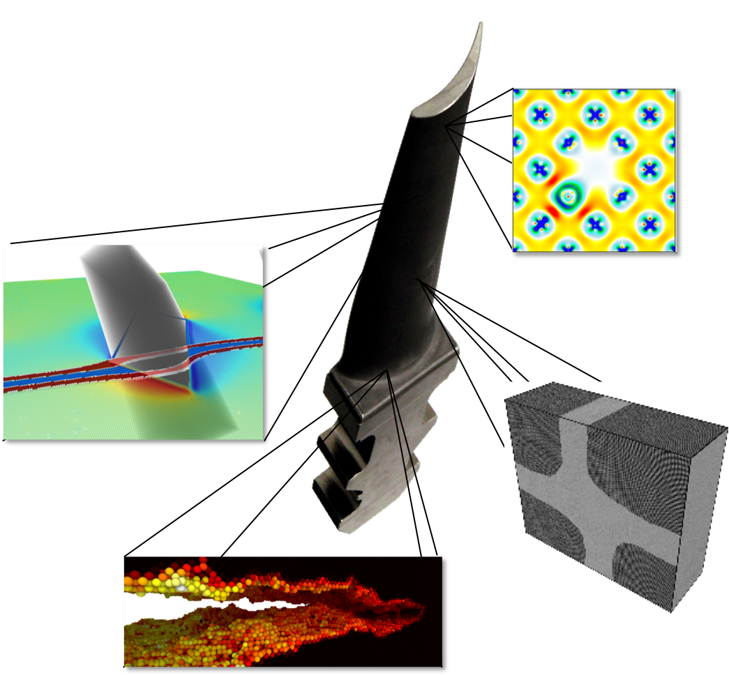
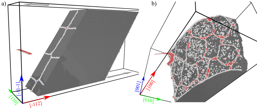
In this chapter, we summarize the main aspects of the present state-of-the-art of atomistic modeling and simulation for superalloys. We start from small calculations with only a few atoms, for which DFT may be employed, and end with atomistic simulations of the microstructure that require many millions of atoms and that are carried out with classical interatomic potentials, see Fig. 1. We list limitations that need to be overcome for the ab initio development of superalloys.
II Methods
II.1 Modeling atomic interactions
The structural stability and mechanical properties of Ni-base superalloys are driven by the distribution of the different chemical elements and the features of the microstructure. Atomistic modeling therefore needs to account for the interaction of the complex alloy chemistry and the diverse geometric features of the atomic structure of imperfections like point defects, interfaces, dislocations, stacking faults, and precipitates. This requires capturing the atomic interactions with appropriate accuracy and tackling simulation cells with a sufficiently large number of atoms. These are antipodal requirements as higher accuracy requires higher complexity and computational effort and therefore leads to smaller simulation cells. The hierarchy of approaches discussed in the following spans the range from highly precise quantum-mechanical calculations at nm length-scales to classical simulations which nowadays can attain m length-scales.
The most accurate approach discussed here involves DFT calculations that provide a numerical solution to the quantum-mechanical equations for the interaction of electrons and ions. The results for metallic systems like Ni-base compounds are highly reliable but the computational effort sets a practical limit to simulation cells with typically a few hundred atoms. This quantum-mechanical description can be simplified in a second-order expansion of DFT Drautz and Pettifor (2011) to the tight-binding (TB) bond model Sutton et al. (1988). This increases the tractable system size to several thousand atoms at the expense of reduced accuracy and an additional parameterization step. The required reference data for the latter are typically energies and forces of crystal structures and defects obtained by DFT calculations. The numerical solution of the simplified quantum-mechanical description can be further accelerated by bond-order potentials (BOPs) (see, e.g., Drautz et al. (2015)). The underlying approximation effectively localizes the range of the quantum-mechanical interaction to a few neighbor shells. With the resulting linear scaling of computational effort with the number of atoms and the possibility for efficient parallelization, the tractable number of atoms is extended to several hundred thousands in a routine simulation Hammerschmidt et al. (2019). A further level of simplification and millions or even billions of atoms can be reached by giving up even the simplified quantum-mechanical description of TB/BOP for a set of short-ranged, analytical functions that mimic the interatomic interaction. This allows constructing approximate models with simple mathematical forms that are parameterized for specific chemical elements and atomic structures. For metallic systems like Ni-base superalloys, pair potentials like the Finnis–Sinclair potential Finnis and Sinclair (1984) and embedded-atom method Daw et al. (1993) are particularly successful and have been parameterized for studying and phases of NiAl Mishin (2004); Purja Pun and Mishin (2009). A more recent development are machine-learning potentials for superalloys Chandran et al. (2018) that replace the fixed set of short-ranged mathematical functions with artificial intelligence approaches in order to interpolate large sets of DFT data for the atomistic description of the superalloy.
II.2 Calculation of structures and energies
The atomistic methods given above start by constructing an atomistic representation of the particular aspect of the superalloy that should be studied. Using the positions and chemical species of the atoms, the different atomistic simulations methods (DFT, TB, BOP, classical potentials) deliver the potential energy of the system, the forces on the individual atoms, and the stresses on the simulation cell.
One of the most basic examples is the computation of the lattice constant of an Ni3Al phase. The corresponding atomistic representation is a unit cell of an fcc (face-centered cubic) crystal lattice with an L12-ordered occupation by Ni and Al atoms in a 3:1 ratio subject to periodic boundary conditions. The computation of the total energy with one of the atomistic methods above depends on the input lattice constant that is chosen for the unit cell. The lattice constant where the total energy takes its minimum value is the equilibrium lattice constant and the corresponding energy is the equilibrium energy. The application of strain tensors to the equilibrium unit cell leads to stresses which can be used to determine the elastic constants of the material.
The defect structures discussed in the following sections are represented atomistically by repetitions of the unit cell and additional modifications. For example, a phase of Ni3Al with 0.2 at.% Ni antisite defects is obtained by a five-fold repetition of the L12-Ni3Al unit cell with four atoms in [100], [010], and [001] directions followed a replacement of one Al atom by an Ni atom. Similarly, the site preference of alloying elements (see, e.g., Jiang and Gleeson (2006)) and their influence on structural stability and elastic constants (see, e.g., Kim et al. (2010)) can be determined by corresponding total-energy calculations where part of the Ni or Al atoms are replaced by the alloying elements of interest.
In these cases, the simulation cell has more degrees of freedom than only the lattice constant, and a structure relaxation needs to be performed. This minimization of the total energy with respect to all structural degrees of freedom leads to a refinement of unit cell size and shape, and atomic positions. The central results of the relaxation of such structures are the detailed atomic structure including displacements and the energetics in the limit of . This is the starting point for further simulations of finite-temperature effects and defect mobility discussed in the next sections. Examples of large-scale simulation setups for / structures, precipitate cutting and fracture are given in Fig. 1.
II.3 Finite temperature calculations
Total energy calculations as discussed in the previous section provide valuable insight into the structural properties and relative stability of metal alloys. The effect of temperature is, however, not included in these calculations. To be able to compare thermodynamic properties at finite temperatures, it is necessary to determine the different entropy contributions to the free energy. Furthermore, additional simulation tools are required to study the dynamical properties on an atomistic level.
Assuming an adiabatic decoupling of the different degrees of freedom, the free energy can be expressed as
| (1) |
where is the total energy at , is the electronic, the vibrational, the magnetic, and the configurational contribution to the free energy. The coupling between different degrees of freedom (electronic–vibrational, vibrational–magnetic) would give rise to extra terms in this expansion. Furthermore, any type of defect (like vacancies) would additionally contribute to the free energy. The electronic free energy, , for bulk systems can be computed with high accuracy based on ab initio calculations Zhang et al. (2017), where methods assuming fixed atomic positions include the self-consistent finite temperature DFT approach, the fixed density of states approximation, and the Sommerfeld approximation. The free energy of atomic vibrations, , usually constitutes the largest contribution at finite temperatures Palumbo et al. (2014). Within the harmonic approximation, the vibrational free energy is calculated from the phonon frequencies which are accessible within a first-principles approach either by density functional perturbation theory Baroni et al. (2001) or by the small displacement approach Kresse et al. (1995). To first order, anharmonicity can be included via the quasiharmonic approximation Palumbo et al. (2014). Here, the dependence of the phonon frequencies on the volume is explicitly considered. At each temperature, the free energy is then accessible as a function of volume, where the minimum denotes the equilibrium volume at the corresponding temperature. Calculating vibrational free energies including full anharmonicity can be achieved on the basis of molecular dynamics (MD) simulations, discussed below. A widely used approach is thermodynamic integration Frenkel and Smit (2001) between a system with known free energy (e.g., within the quasiharmonic approach) and the system of interest. MD simulations based on energies and forces from ab initio calculations (AIMD) can provide very accurate results, but are also computationally very demanding. Including magnetic contributions to the free energy, , from first-principles calculations is rather challenging Körmann et al. (2016), usually requiring the setup of model Hamiltonians derived from ab initio calculations. These contributions are, however, important in magnetic transition metals such as Ni, Co, and Fe, where they significantly impact thermodynamic quantities such as the free energy and the specific heat Körmann et al. (2011). In disordered alloys, the last term, , is often approximated using the entropy of mixing for an ideal solid solution. More sophisticated approaches have been developed based on a cluster expansion approach that aim to sample the space of all possible arrangements of different atom types on a fixed crystal lattice van de Walle et al. (2007); Zhang and Sluiter (2016). Together with Monte Carlo (MC) sampling approaches in different thermodynamic ensembles it becomes possible to investigate phenomena such as order-disorder transitions, precipitate formation, or phase diagrams Goiri and Van der Ven (2016); Maisel et al. (2014).
To investigate the dynamical behavior of materials at finite temperatures, MD simulations Frenkel and Smit (2001); Allen and Tildesley (2017) constitute nowadays the standard workhorse for atomistic simulations. In MD, atoms are treated as classical particles following Newton’s equations of motion. Simulations can be performed in various thermodynamic ensembles by using the corresponding thermostats and barostats, including the microcanonical, canonical, and isothermal–isobaric ensembles. Advances in numerical algorithms and increasing computational resources allow performing simulations with up to billions of atoms. The development of elaborate program packages Plimpton (1995) has contributed to a widespread use of MD simulations to study materials properties. The two main difficulties in MD simulations are an accurate description of the interatomic interactions and the accessible timescales. Ab initio MD Marx and Hutter (2009) is based on highly accurate energies and forces, but system sizes are limited to a few hundred atoms. Empirical potentials, on the other hand, are usually not reliable for complex, multicomponent alloys and often have difficulties to properly represent complex structural environments, such as dislocation cores or during crack propagation. The timescale problem in MD simulations arises when the process of interest involves sizeable energy barriers between two metastable states of the system, e.g., during vacancy mediated diffusion (see also Section IV.2). This is due to a separation of timescales between the fast vibrations and the comparably slow changes in structure or exchange of atomic positions. A number of accelerated MD techniques Voter et al. (2002) has been developed to facilitate the escape from metastable states in the course of the simulation while preserving the correct dynamics. Another approach is kinetic Monte Carlo (KMC) Bortz et al. (1975); Fichthorn and Weinberg (1991) simulations where a rate constant is determined for each process connecting two metastable states and the dynamics is given by a stochastic state-to-state trajectory that again preserves the correct timescale. If a suitable mapping of the investigated system onto a finite state space can be identified, then the corresponding rate constants for all processes can be determined with high accuracy based on electronic structure calculations. The analysis of dynamical simulations provides insight into the atomistic mechanisms and gives access to macroscopic transport coefficients via the corresponding Green–Kubo relations Frenkel and Smit (2001); Allen and Tildesley (2017), as, e.g., diffusion coefficients, shear viscosity, or thermal conductivity. These quantities can directly be compared to experimental measurements.
III Thermodynamic stability
A central concept for determining the structural stability of crystalline phases by atomistic simulations are differences of total energies from simulations for different systems. As an example, the formation energy of the Ni3Al phase with respect to the elemental ground states is taken as the energy difference between the L12 Ni3Al total energy and the total energy of fcc-Al and fcc-Ni where each total energy is obtained in a separate simulation. With proper accounting of the chemical compositions, one can compare different crystal structures with different chemical composition by convex-hull constructions. The resulting information on the energetically most favorable crystal structure for a given chemical composition at and further entropy contributions can be considered in CALPHAD assessments of phase diagrams of compound systems, see Chapter 2.
The concept of energy differences is also used to investigate the stability of defects. The segregation energy of an alloying element to a defect, e.g., is taken as energy difference between the total energy of a supercell with the alloying element positioned at the defect and a second supercell with the alloying element far away from the defect. Similarly, the formation energies of point defects (e.g., vacancies), line defects (e.g., dislocations), planar defects (e.g., stacking faults), and extended defects (e.g., precipitates) are computed from the difference in energy of calculations with and without the corresponding defect.
A certain limitation of the atomistic approaches for the case of typical multicomponent superalloys is a realistic representation of their chemical complexity. Classical interaction models, on the one hand, usually lack reliable multicomponent parameterizations, and DFT calculations, on the other hand, are hardly possible due to (i) the size of the required supercells and (ii) the combinatorially large number of atom distributions within the supercell. An alternative approach are structure maps Pettifor and Podloucky (1984); Pettifor (1986a); Hammerschmidt et al. (2008); Seiser et al. (2011a); Bialon et al. (2016) that chart the trends of the structural stability Pettifor (1986b); Seiser et al. (2011b); Hammerschmidt et al. (2013) in low-dimensional representations. The application of structure maps to superalloys could, e.g., rationalize the formation of detrimental topologically close-packed (TCP) phases in the CMSX4-like Ni-base superalloy ERBO/1 in the as-cast and heat-treated state Lopez-Galilea et al. (2016); Hammerschmidt et al. (2016), in low-cycle fatigue-tests Meid et al. (2019), and during repair by vacuum plasma spray Kalfhaus et al. (2019).
IV Point defects
In general, there are three types of point defect that we consider in bulk phases: vacancies, where an atom is missing from a particular lattice site; substitutional defects, where a matrix atom is replaced by another element; and interstitial defects, where additional atoms are present in between regular lattice sites. In the following we will focus on the former two, vacancies and substitutional defects.
IV.1 Thermodynamic properties
One of the important thermodynamic quantities is the defect formation energy, that is, the change in energy due to the creation of a defect. Atomistically, the defect formation energy can be computed within a supercell approach as the difference between the total energy of supercells with and without the corresponding defect, see Freysoldt et al. (2014) for a review. The vacancy formation energy (VFE) in pure Ni is, e.g., given by
| (2) |
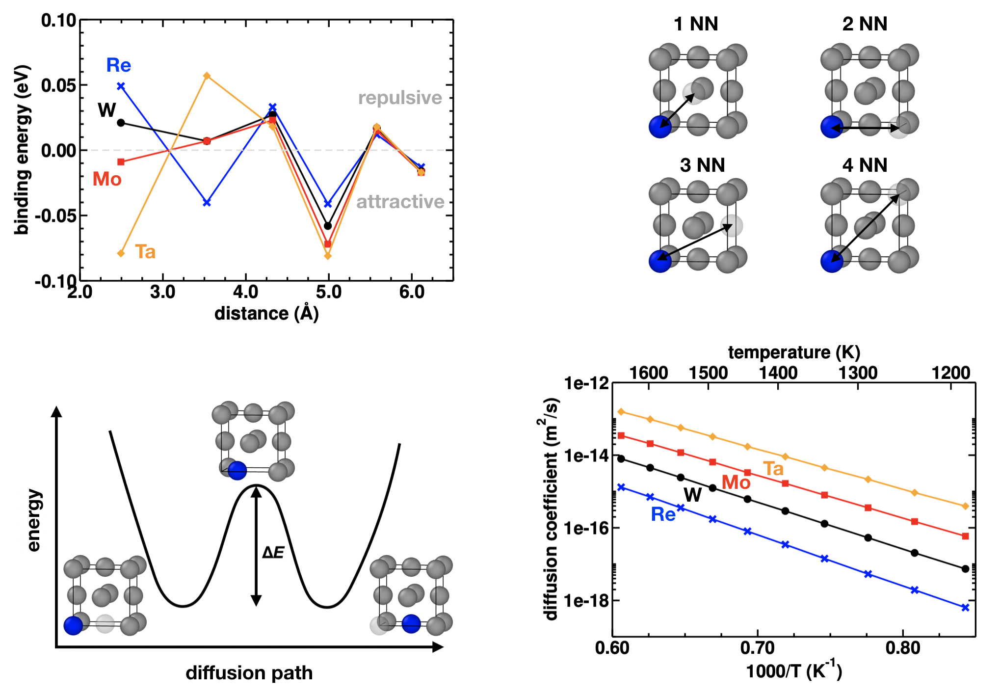
where is the number of atoms in the supercell. The size of the supercell determines the minimum defect concentration and needs to be carefully tested to avoid artificial defect–defect interactions Rogal et al. (2014). Similarly, the magnitude of the interaction between point defects can be calculated as the energy difference between an isolated defect, that is a single defect in a large supercell, and two or multiple defects at a certain distance. Attractive interactions indicate binding or clustering, whereas repulsive interactions favor a random distribution of point defects in the matrix. In Fig. 2 the interaction energies between a vacancy and solute atoms (Re, W, Mo, Ta) in an Ni matrix are shown. These calculations demonstrate that single Re atoms do not bind vacancies Schuwalow et al. (2014); Zhang et al. (2014a) and that this could be dismissed as a possible hypothesis for the Re effect. Similarly, nonmagnetic electronic structure calculations of interaction energies between Re atoms in Ni revealed that Re does not tend to form clusters Mottura et al. (2012), eliminating another speculation concerning the cause of the Re effect. For the Ni–Re system the results do, however, strongly depend on the magnetic state of the system He et al. (2016). In multicomponent systems, the defect formation energy depends on the local chemical environment as well as on the global composition. In random solid solutions, it is in addition unknown which atom type previously occupied the defect site, which requires considering a properly weighted average over possible configurations Rogal et al. (2014). In chemically ordered phases, the formation energy of antisite defects (an atom of one sublattice occupies a site on another sublattice) determines how the system compensates off-stoichiometric compositions. In the L12 ordered Ni3Al phase, the formation energy of antisite defects is much lower than the vacancy formation energy de Koning et al. (2002); Jiang et al. (2006); Gopal and Srinivasan (2012); Zhang et al. (2014b); Goiri and Van der Ven (2016) and thus structural vacancies are not observed for off-stoichiometric compositions Badura-Gergen and Schaefer (1997). Furthermore, a number of first-principle studies have investigated the site preference of ternary alloying elements in the phase Jiang et al. (2006); Ruban et al. (2014); Ruban and Skriver (1997); Kim et al. (2012), which was shown to influence the mechanical properties of this phase Rawlings and Staton-Bevan (1975).
IV.2 Mobility
Solid state self-diffusion and the diffusion of substitutional defects are mainly mediated by vacancies. On the atomic scale, a diffusion process involves the exchange of an atom with a neighboring vacancy which is associated with an energy barrier as shown in Fig. 2. The minimum energy path along the diffusion process can be determined using the nudged-elastic band (NEB) approach Henkelman et al. (2000) or the string method E et al. (2007) with a high degree of accuracy using electronic structure methods. The corresponding microscopic diffusion barriers can either be used in analytical models LeClaire and Lidiard (1956); Goswami and Mottura (2014) or as input parameters to kinetic Monte Carlo (KMC) Bortz et al. (1975); Schuwalow et al. (2014) simulations to calculate macroscopic diffusion coefficients. In Fig. 2 diffusion coefficients of alloying elements in Ni as a function of temperature are shown determined by DFT calculations combined with KMC simulations Schuwalow et al. (2014). The values for the diffusion activation energies extracted from the Arrhenius plot can directly be compared with experimental measurements of tracer diffusion coefficients. Such simulations also allow directly comparing the mobility of alloying elements in Ni and Co Neumeier et al. (2008) as a quantity of interest in the investigation of Ni- and Co-base superalloys. Furthermore, the simulations provide insight into the mobility of vacancies and how the presence of alloying elements influences vacancy transport Schuwalow et al. (2014); Goswami and Mottura (2014); Grabowski et al. (2018); Goswami and Mottura (2019). In complex alloys, the diffusion properties depend on the composition. An accurate description on an atomistic level requires taking into account interaction energies between solute atoms, as well as their influence on microscopic diffusion barriers Grabowski et al. (2018); Goswami and Mottura (2019). This also applies to chemically ordered alloys such as the Ni3Al phase where diffusion processes might take place on the same sublattice or cause a swap between sublattices Duan (2007); Gopal and Srinivasan (2012); Zhang et al. (2014b). In multicomponent alloys, an accurate mapping of all possible diffusion processes becomes rather involved. Here, KMC simulations can be combined with more advanced approaches such as a cluster expansion of the diffusion barriers parameterized by electronic structure calculations Van der Ven et al. (2001).
V Line defects
Line defects, here mainly dislocations, can be studied both by DFT calculations and atomistic simulations with TB/BOP models or classical potentials. The small number of atoms that can be treated with DFT approaches, however, requires advanced methods for the boundary conditions and allows only for static calculations Woodward et al. (2008); Tan et al. (2019). The motion of extended dislocations, as well as their interactions with each other and other defects can, so far, only be simulated using interatomic potentials with their known limitations in accuracy and chemical complexity.
V.1 Dislocation core structure
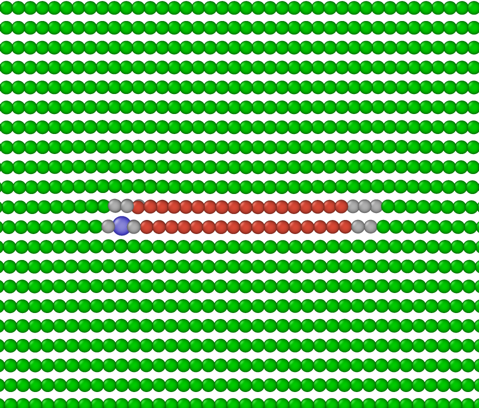
Dislocations in pure Ni as model systems for the phase have been extensively studied Szelestey et al. (2003); Bitzek and Gumbsch (2005); Bianchini et al. (2016); Tan et al. (2019) also with respect to segregation of solute atoms Liu and Wang (2017); Katnagallu et al. (2019). In atomistic simulations, these dislocations are generated by displacing the atoms according to an analytic solution of the displacement field around the dislocation, followed by a relaxation of the atomic positions. For an edge dislocation this leads to two partial dislocations separated by an intrinsic stacking fault as shown in Fig. 3.
Dislocations in the phase are much more diverse, including partial dislocations bounding different planar defects (see Section VI), different possible glide planes and Burgers vectors Reed and Rae (2014). Consequently, most atomistic studies were directed to reproduce experimentally observed dislocation structures and to determine their properties.
Understanding 110 screw superdislocations in Ni3Al is of particular importance due to their potential for forming Kear–Wilsdorf (KW) lock configurations Kear and Wilsdorf (1962) and thus leading to the anomalous yield behavior of L12 alloys. Therefore, much effort has been invested during the 1980s and 1990s to investigate their core structure Yamaguchi et al. (1982); Paidar et al. (1982); Yoo (1986, 1987); Farkas and Savino (1988); Yoo et al. (1989); Paidar et al. (1984); Parthasarathy and Dimiduk (1996); Wen and Lin (1997); Wen and Li (1998). Depending on the simulation details, different core structures are possible, including dissociation of the superdislocation on a plane into a pair of superpartial dislocations separated by an antiphase boundary (APB) and nonplanar configurations. The detailed locking mechanism is commonly believed to involve the thermally-activated formation of Paidar–Pope–Vitek (PPV) locks Paidar et al. (1984), which has been recently studied in detail Parthasarathy and Dimiduk (1996); Ngan et al. (2004); Rao et al. (2012), including the use of NEB calculations to calculate activation energies Ngan et al. (2004); Rao et al. (2012). In this context, it is important to note that the activation barriers depend strongly on the studied configuration. Considering, e.g., the interaction with forest dislocations can significantly reduce the activation energy for the critical cross-slip process Rao et al. (2012). Recent atomistic simulations suggest furthermore, that under applied stress and elevated temperatures also edge superdislocations can show nonplanar dissociation leading to complex Lomer–Cottrell locks Xie et al. (2011, 2013); Fan et al. (2016).
In addition to the usual 110 superdislocations also edge superdislocations were observed to penetrate the particles, in particular during high temperature, low stress creep, where this process is believed to be the rate limiting step Eggeler and Dlouhy (1997); Srinivasan et al. (2000); Link et al. (2005). The dissociation of a perfect edge superdislocation in Ni3Al was studied by Kohler et al. Kohler et al. (2006), who found that it could dissociate in a symmetric dissociation similar to the Hirth lock in fcc structures, an asymmetric dissociation and a dissociation into two interlocked dislocations, with the Hirth lock being the most stable configuration. HRTEM observations and image simulations by Srinivasan et al. Srinivasan et al. (2000), however, showed a somewhat different core structure, which might be related to the coupled glide-climb process necessary for the motion of dislocations.
V.2 Dislocation mobility and solid solution strengthening
The Peierls stress necessary to initiate dislocation motion can be easily determined by quasistatic calculations on infinite straight dislocation lines in a slab geometry with periodic boundary conditions subjected to different shear stresses. The same setup can be used to measure the temperature-dependent drag coefficient caused by the interaction of phonons with the moving dislocation by performing MD simulations at different temperatures. For pure Ni, these parameters have been determined by Bitzek et al. Bitzek and Gumbsch (2004, 2005). Alternatively, the Peierls stress can also be determined by DFT calculations of the generalized stacking-fault energy in a Peierls–Nabarro model as, e.g., in Wang and Sehitoglu (2014) for Ni3Al. Although an important parameter in discrete dislocation dynamics (DDD) simulations, the drag coefficient , see Chapter 12, for dislocations or superdislocations in Ni3Al has not yet been determined by atomistic simulations.
The strengthening effect of different solutes can be predicted, e.g., by combining DFT calculations of solute–dislocation interaction energies with a Labusch-type model Leyson et al. (2010). Such an approach has, however, not yet been used to calculate solid solution strengthening in the or phases of Ni-base superalloys. Alternatively, direct MD simulations of dislocation motion in solid solutions can be used to determine parameters like static and dynamic threshold stresses and effective “friction coefficients” for dislocations, including superdislocations in Rodary et al. (2004); Marian and Caro (2006); Zhang et al. (2013); Fan et al. (2016). This approach depends critically on the availability and quality of atomic interaction potentials. Although recently simulations have focused on concentrated solid solutions Rao et al. (2017), no simulations were so far performed on realistic model systems for Ni-base superalloys. Please also refer to Chapter 14 regarding the modeling of solid solution strengthening in crystal plasticity.
It needs to be stressed that the above approaches to study dislocation mobility neglect diffusive processes. The shearing of the phase by partial dislocations, however, requires reordering steps that involve short-range diffusion Kovarik et al. (2009); Zhou et al. (2011). Modeling such concerted diffusive–displacive processes at the atomic scale remains one of the fundamental challenges for atomistic simulations Li et al. (2011). The study of dislocation climb by atomistic simulations is therefore in its infancy Sarkar et al. (2012); Baker and Curtin (2016), and the effects of solute atoms on the climb mobility are yet to be investigated at the atomic scale.
VI Interfaces and planar defects
The calculation of the / interface of a superalloy with realistic chemical complexity requires large supercells and proper combinatorial sampling of the disordered phase. A common approximation is therefore to mimic the phase by pure Ni which has been used successfully in calculations with classical EAM (embedded-atom method) potentials of different interfaces Mishin (2014) and in DFT calculations of the influence of alloying elements on the interface energy Liu et al. (2017).
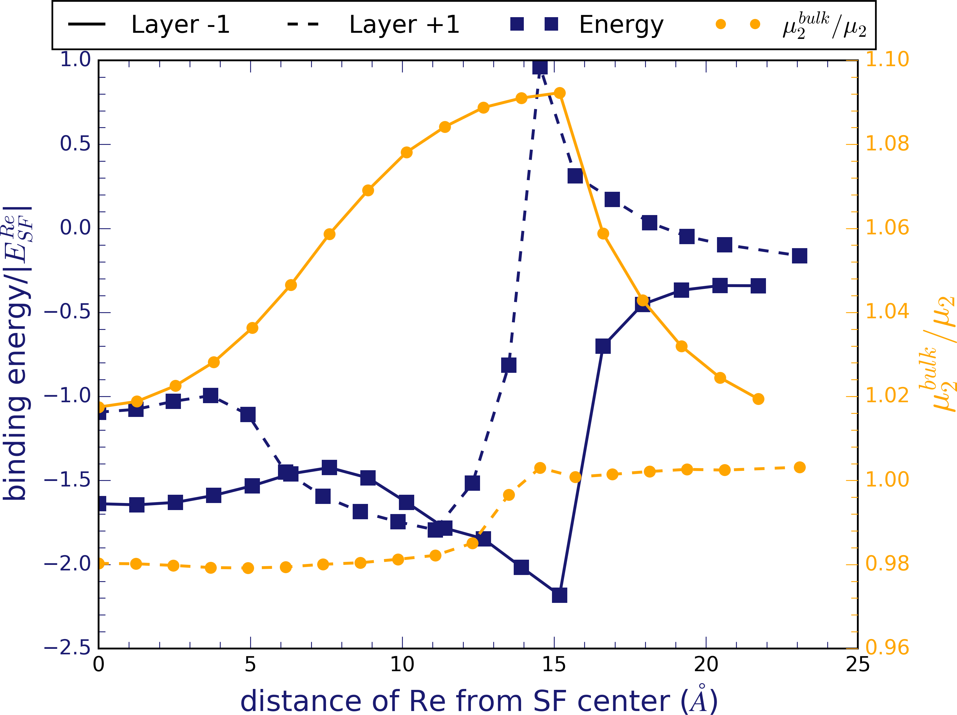
The mechanisms of the plastic deformation of superalloys in the different pressure and temperature regimes are discussed in detail in Chapter 6. The plastic deformation is governed by cutting processes (see, e.g., Agudo Jacome et al. (2014)) and by microtwinning (see, e.g., Kovarik et al. (2009); Barba et al. (2017)). These involve several steps including dislocation dissociation into partials and the movement of the partials, as well as the segregation to the partial and to stacking faults between partials and behind the trailing partial. The most important planar faults in the context of shearing deformation are superlattice intrinsic stacking faults (SISF), superlattice extrinsic stacking faults (SESF), antiphase boundaries (APB), and pairs of twin boundaries. These phenomena at the atomic level are ideal candidates for atomistic simulations, particularly regarding clarification of (i) the relative formation energy of different planar faults (see, e.g., Titus et al. (2015)), (ii) the influence of alloying elements on the fault energy, and (iii) the segregation of alloying elements to the fault plane (see, e.g., Viswanathan et al. (2015); Eggeler et al. (2016)).
The majority of recent calculations for planar faults are, in fact, performed on the basis of DFT calculations due to a lack of reliable alternatives for multicomponent systems. The stacking faults are accessible to atomistic simulations by supercell calculations and, in few cases, by an approximation with an axial Ising model (AIM) Denteneer and Van Haeringen (1987). Disorder of the atoms on the crystal lattice (due to, e.g., off-stoichiometry or finite temperature) can be introduced by special quasirandom structures (SQS) Zunger et al. (1990), by cluster expansions (CE), or by mean-field approaches like the coherent phase approximation (CPA).
The energy of the APB that is formed during cutting of a dislocation is of central importance for shear resistance, see Chapter 6. Several recent works, including supercell DFT calculations Chandran and Sondhi (2011); Vamsi and Karthikeyan (2014); Crudden et al. (2014); Kumar et al. (2018), DFT-based CE Sun et al. (2017), and DFT-based CPA Gor (2016), showed consistently that alloying with group IV (e.g., Ti) and group V (e.g., Ta) transition-metal elements can considerably increase the APB energy and hence the shear resistance. Corresponding works for SISF and SESF were carried out with supercell DFT calculations Wen et al. (2012); Kumar et al. (2018) and AIM-based approximations Breidi et al. (2018). Considerably fewer works are available that performed corresponding calculations for the microtwinning mechanism during creep. The segregation of selected alloying elements to SESF and SISF was determined by supercell DFT calculations Eurich and Bristowe (2015) that were recently extended and interpreted in terms of reordering kinetics and intermediate fault structures Rao et al. (2018).
VII Microstructure and defect–defect interactions
Simulating the / microstructure of Ni-base superalloys, its deformation, and final fracture, as well as the direct interaction between defects, requires atomistic simulations with large numbers of atoms that presently can only be realized with semiempirical potentials. Such simulations are very useful in further developing our mechanistic understanding of deformation processes and can help with the interpretation of experimental observations, which due to their limited time resolution might not capture all relevant details.
VII.1 Deformation of individual precipitates
Although not directly related to the study of superalloys under typical application conditions, recent experimental Landefeld et al. (2012); Maaß et al. (2012) and MD simulation Amodeo et al. (2014); Shreiber and Mordehai (2015); Houllé et al. (2018) studies on individual nanocubes under compression allowed to investigate the deformation behavior of the pure phase. These defect-free cubes deform by the nucleation of Shockley partial dislocations, leaving behind complex stacking-faults that can at larger strains transform into a pseudotwin structure Amodeo et al. (2014). The detailed deformation mechanisms, however, depend critically on the used potentials Shreiber and Mordehai (2015), showing the importance of performing well-controlled experiments to validate interatomic potentials. Combining such well-defined experimental or simulation studies on the individual phases, as well as on the / microstructure can help elucidate the influence of constraints and misfit stresses on the mechanical performance of single-crystalline superalloys Houllé et al. (2018).
VII.2 Interfacial dislocation networks
The misfit dislocation network (MFDN) that forms directly upon energy minimization due to the lattice misfit between the and the phases has been the subject of many atomistic simulations Zhu and Wang (2005); Yashiro et al. (2007); Xie et al. (2009); Wu et al. (2011); Zhu et al. (2013); Yu et al. (2015); Ye et al. (2015); Prakash et al. (2015); Li et al. (2018); Ding et al. (2018). These studies have been performed on systems in which the phase is represented by pure Ni, whereas the phase is modeled by stoichiometric Ni3Al. The resulting lattice misfit of –, depending on the potential, is one order of magnitude larger than in typical superalloys, which furthermore have a negative misfit Parsa et al. (2015). Only recent studies included alloying elements Ding et al. (2018) and nonstoichiometric compositions Prakash et al. (2015).
The most important critique of these simulations is, however, their artificial construction of the interfacial dislocation network, often using perfectly planar interfaces. In reality, the interfacial dislocation network (IDN) forms by deposition of channel dislocations under creep conditions and their subsequent rearrangement Link et al. (2005). In this respect, the artificial MFDN can only be seen as an idealized arrangement of interfacial dislocations that would most effectively reduce the misfit stresses. However, in most simulation studies, the IDN dislocations show a compact core, see Fig. 4(a). This is due to the fact that the interface plane is not a natural glide plane for dislocations in the fcc crystal structure. By using realistic interface morphologies, it was recently shown that dislocations in the MFDN assume configurations in which they spread out on planes, and can form stair-rod junctions as also observed in multiple experiments Prakash et al. (2015). In addition, also the Burgers vectors in the MFDN changed due to the interface curvature (Prakash et al., 2015). An example for a realistic MFDN can be seen in Fig. 4(b).
VII.3 Dislocation–precipitate interactions
The interaction of matrix dislocations with precipitates is the main reason for the high creep strength of Ni-base superalloys. Here, atomistic simulations can in principle be used to identify the conditions under which single dislocations or superdislocations can cut into the phase. The interaction between single, infinitely long edge, or screw dislocations with a regular array of spherical precipitates with diameters up to 6 nm was studied by Proville and Bako Proville and Bakó (2010). They showed a transition from dislocation cutting to Orowan bowing with increasing precipitate diameter. Kohler et al. Kohler et al. (2005) used a similar methodology but focused on even smaller precipitates. The more relevant case of studying the interaction of super dislocations with spherical precipitates was recently simulated by Hocker et al. Hocker et al. (2019) and Kirchmayer et al. Kirchmayer et al. (2020). The former group used a similar setup as in Proville and Bakó (2010); Kohler et al. (2005) using regular arrays of spherical precipitates. In that case it was found that, depending on whether the distance between the superpartial dislocations is larger or smaller than the precipitate diameter (corresponding to weak or strong coupling between the superpartial dislocations Hüther and Reppich (1978)), different partial dislocations govern the critical resolved shear stress (CRSS) to pass the precipitate. Kirchmayer et al., however, used realistic precipitate morphologies and arrangement obtained from atom probe tomography (APT), and were thus able to show that for a relatively wide distribution of precipitate sizes weak and strong pair coupling can be at play simultaneously Kirchmayer et al. (2020). Spherical precipitates were also studied by Takahashi et al. Takahashi and Terada (2011) and Kondo et al. Kondo et al. (2018), however, in their simulations the precipitates consisted of the phase which were cut by superdislocations from the surrounding Ni3Al phase. Besides providing information about the dislocation–precipitate interaction processes, such simulations can provide – with the usual limitations of the unrealistic compositions – quantitative information on precipitate cutting stresses and on the relative importance of, e.g., the coherency stresses, the APB energy or the energy to create an interface step.
Single-crystalline superalloys are strengthened by the presence of large, cuboidal precipitates that force the dislocations to glide in narrow channels. Relatively few detailed atomistic studies of dislocation–precipitate interactions in this type of microstructure have been reported so far. Such studies would, however, be important to inform discrete dislocation dynamics simulations, see Yashiro et al. (2006) and Chapter 12, in particular regarding, e.g., the influence of local interface curvature and chemical composition gradients on dislocation–precipitate interactions. The motion of dislocations into channels bounded by two cuboidal precipitates was first studied by Yashiro et al. Yashiro et al. (2002). Recently, Xiong et al. Xiong et al. (2017) performed a quantitative study to determine the stress required for matrix dislocations to penetrate into the channel in a similar setup, however, with a preexisting MFDN. Overall, they found an inverse proportionality between the critical stress and the channel width. The influence of the MFDN on the interaction of channel dislocations with the precipitate was recently studied using different setups Zhu et al. (2013); Prakash et al. (2015); Xiong et al. (2017), see also Fig. 4. The simulations with a realistic MFDN and dislocation core structures resulting from an APT-informed sample showed that in particular the colinear interaction of the first channel dislocation with a misfit dislocation protects the precipitate from being sheared by a superdislocation as due to the dislocation annihilation no trailing superpartial is available Prakash et al. (2015). Prakash and Bitzek Prakash and Bitzek (2017) furthermore studied the interaction of dislocation loops with various shapes and arrangements of precipitates. The different stress fields caused by the misfit stresses lead to significant differences regarding the cutting of precipitates and the penetration of the dislocation into the channels, demonstrating the importance of taking deviations from the idealized morphologies and topologies into account.
VII.4 Deformation and fracture of superalloys
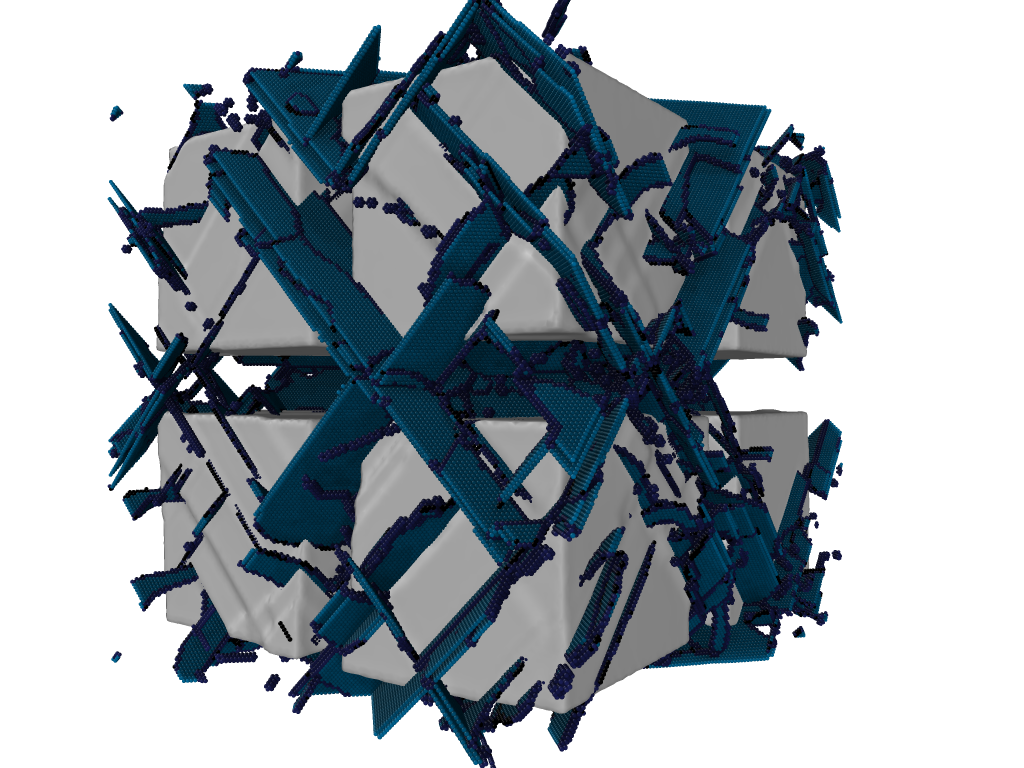
Interestingly, relatively few large-scale MD studies exist on the plastic deformation and stress–strain response of superalloys with / microstructures. Ma et al. Ma et al. (2016) performed tensile tests on an Ni/Ni3Al microstructure, however, made up of an unrealistic checker-board arrangement of cubic and crystallites. Using one cubic precipitate surrounded by , Li et al. Li et al. (2018) showed a tension compression antisymmetry in the stress-strain response. The result of a recent MD simulation with eight cubes arranged according to an idealized / microstructure is shown in Fig. 5.
All these simulation results are, however, of limited relevance as under these conditions, the deformation is governed by the homogeneous nucleation of dislocations at extremely high strain rates of the order of to per second. This is in stark contrast to typical experimental conditions and samples that contain preexisting ingrown dislocations. This highlights the need for a multiscale approach in which the information from atomistic simulations are used in, e.g., DDD simulations at lower strain rates, larger sizes, and with more realistic initial dislocation densities. In particular, for the later stages of deformation where creep or fatigue fracture becomes relevant, atomistic simulations are uniquely positioned to provide criteria for crack advance or dislocation nucleation to meso- and continuum scale models Bitzek et al. (2015); Möller et al. (2018). The corresponding atomistic studies regarding crack nucleation and crack propagation in / microstructures Liu et al. (2013); Yu et al. (2014); Shang et al. (2018) are, however, still in their infancy.
VIII Limitations of atomistic simulations for superalloy design
While progress in atomistic theory in the past years means that many properties of superalloys became accessible, other aspects of superalloy performance are not directly accessible by atomistic simulations. Here we summarize the main limitations of present day atomistic simulations for superalloys.
-
•
While DFT is used heavily in atomistic simulations for superalloys, the approximations in current exchange correlation functionals still limit the use of DFT data for alloy design. For example, formation energies and enthalpies computed by DFT can in principle be included in CALPHAD assessments, but accuracy of the DFT data, compatibility to experimental data sets and exhaustive DFT data for multicomponent alloys remain issues that need to be resolved together with an update of the CALPHAD approach to bring it closer to atomistic simulations. The same holds true for elastic constants and interface energies that are required for phase field simulations.
-
•
Superalloys are multicomponent materials. Interatomic potentials for multicomponent materials are not available today. This means that atomistic simulations often cannot provide input for mesoscale or continuum models. The development of quantitatively accurate multielement interatomic potentials remains one of the grand challenges in the field.
-
•
The time scale of atomistic molecular dynamics simulations is limited by the time step for the numerical integration of the atomic trajectories. The time step is on the order of s. This means that time scales required for studying processes that include diffusion, e.g., dislocation climb-glide creep, are often not accessible. Expanding atomistic simulations to diffusive time scales is one of the major challenges for the field.
-
•
An even greater gap exists between atomistic simulations of microstructural events and the modeling of plasticity. Models of plasticity need to define their parameters explicitly in such a way that atomic-scale simulation procedures may be developed to provide the required parameters.
-
•
Continuum models are sometimes incompatible or at least not directly compatible with atomistic simulations. The transfer of results from atomistic simulations to continuum descriptions remains one of the roadblocks for a first principles guided design of superalloys. Both the atomistic and continuum modeling communities need to make great strides towards a more efficient exchange.
IX Summary: modeling Ni-base superalloys from electrons to microstructures
The rapid progress in atomistic modeling and simulation over the past years brings first-principles computational design of superalloys into reach. Today, atomistic modeling enables the prediction of key aspects of superalloy properties, from solute bond chemistry to microstructural properties. We reviewed the different representations of the interatomic interaction that are commonly used for modeling superalloys, briefly introduced atomistic simulation methods in the context of superalloys, and outlined properties of superalloys that can be computed by atomistic simulations.
Limitations of atomistic simulation methods means that many properties of superalloys are not accessible today and the development of “approximate practical methods” that Paul Dirac envisioned nearly a century ago will remain a focus of the atomistic simulations community.
We hope that the present chapter may induce discussions and collaborations that will contribute to further narrow the gap between atomistic simulation and superalloys, and in this way help advance the design of novel superalloys.
Acknowledgement
We are grateful to A.P.A. Subramanyam, H. Lyu, F. Houllé, A. Prakash, and J.J. Möller for their help in preparing some of the figures. We acknowledge financial support from the German Research Foundation (DFG) through projects C1, C2, and C3 of the collaborative research center SFB/TR 103.
References
- Dirac (1929) P. Dirac, 123, 714 (1929).
- Hohenberg and Kohn (1964) P. Hohenberg and W. Kohn, 136, B864 (1964).
- Kohn and Sham (1965) W. Kohn and L. Sham, 140, A1133 (1965).
- Van Noorden et al. (2014) R. Van Noorden, B. Maher, and R. Nuzzo, Nature 514, 550 (2014).
- Drautz and Pettifor (2011) R. Drautz and D. Pettifor, 84, 214114 (2011).
- Sutton et al. (1988) A. Sutton, M. Finnis, D. Pettifor, and Y. Ohta, 21, 35 (1988).
- Drautz et al. (2015) R. Drautz, T. Hammerschmidt, M. Cak, and D. Pettifor, 23, 074004 (2015).
- Hammerschmidt et al. (2019) T. Hammerschmidt, B. Seiser, M. Ford, A. Ladines, S. Schreiber, N. Wang, J. Jenke, Y. Lysogorskiy, C. Teijeiro, M. Mrovec, et al., Comp. Phys. Comm. 235, 221 (2019).
- Finnis and Sinclair (1984) M. Finnis and J. Sinclair, 50, 45 (1984).
- Daw et al. (1993) M. Daw, S. Foiles, and M. Baskes, 9, 251 (1993).
- Mishin (2004) Y. Mishin, 52, 1451 (2004).
- Purja Pun and Mishin (2009) G. Purja Pun and Y. Mishin, 89, 3245 (2009).
- Chandran et al. (2018) M. Chandran, S. Lee, and J.-H. Shim, 26, 025010 (2018).
- Jiang and Gleeson (2006) C. Jiang and B. Gleeson, 55, 433 (2006).
- Kim et al. (2010) D. Kim, S. Zhang, and Z. Liu, Intermetallics 18, 1163 (2010).
- Zhang et al. (2017) X. Zhang, B. Grabowski, F. Körmann, C. Freysoldt, and J. Neugebauer, 95, 165126 (2017).
- Palumbo et al. (2014) M. Palumbo, B. Burton, A. Costa e Silva, B. Fultz, B. Grabowski, G. Grimvall, B. Hallstedt, O. Hellman, B. Lindahl, A. Schneider, et al., 251, 14 (2014).
- Baroni et al. (2001) S. Baroni, S. de Gironcoli, A. Dal Corso, and P. Giannozzi, Rev. Mod. Phys. 73, 515 (2001).
- Kresse et al. (1995) G. Kresse, J. Furthmüller, and J. Hafner, 32, 729 (1995).
- Frenkel and Smit (2001) D. Frenkel and B. Smit, Understanding Molecular Simulations: From Algorithms to Applications (Academic Press, 2001), 2nd ed.
- Körmann et al. (2016) F. Körmann, T. Hickel, and J. Neugebauer, 20, 77 (2016).
- Körmann et al. (2011) F. Körmann, A. Dick, T. Hickel, and J. Neugebauer, 83, 165114 (2011).
- van de Walle et al. (2007) A. van de Walle, G. Ghosh, and M. Asta, in Applied Computational Materials Modeling: Theory, Simulation and Experiment, edited by G. Bozzolo, R. Noebe, P. Abel, and D. Vij (Springer US, Boston, MA, 2007), pp. 1–34.
- Zhang and Sluiter (2016) X. Zhang and M. Sluiter, 37, 44 (2016).
- Goiri and Van der Ven (2016) J. Goiri and A. Van der Ven, 94, 094111 (2016).
- Maisel et al. (2014) S. Maisel, N. Schindzielorz, A. Mottura, R. Reed, and S. Müller, 90, 094110 (2014).
- Allen and Tildesley (2017) M. Allen and D. Tildesley, Computer Simulation of Liquids (Oxford University Press, 2017), 2nd ed.
- Plimpton (1995) S. Plimpton, J. Comp. Phys. 117, 1 (1995), http://lammps.sandia.gov.
- Marx and Hutter (2009) D. Marx and J. Hutter, Ab initio Molecular Dynamics: Basic Theory and Advanced Methods (Cambridge University Press, 2009), 1st ed.
- Voter et al. (2002) A. Voter, F. Montalenti, and T. Germann, 32, 321 (2002).
- Bortz et al. (1975) A. Bortz, M. Kalos, and J. Lebowitz, J. Comp. Phys. 17, 10 (1975).
- Fichthorn and Weinberg (1991) K. Fichthorn and W. Weinberg, J. Comp. Phys. 95, 1090 (1991).
- Pettifor and Podloucky (1984) D. Pettifor and R. Podloucky, 53, 1080 (1984).
- Pettifor (1986a) D. Pettifor, 19, 285 (1986a).
- Hammerschmidt et al. (2008) T. Hammerschmidt, B. Seiser, R. Drautz, and D. Pettifor, in Superalloys 2008: Proc. of the eleventh International Symposium on Superalloys, edited by Reed, RC and Green, KA and Caron, P and Gabb, TP and Fahrmann, MG and Huron, ES (TMS, Minerals, Metals & Materials Society, Champion, USA, 2008), pp. 847–853.
- Seiser et al. (2011a) B. Seiser, R. Drautz, and D. Pettifor, 59, 749 (2011a).
- Bialon et al. (2016) A. Bialon, T. Hammerschmidt, and R. Drautz, 28, 2550 (2016).
- Pettifor (1986b) R. Pettifor, D.G.and Podloucky, 19, 315 (1986b).
- Seiser et al. (2011b) B. Seiser, T. Hammerschmidt, A. Kolmogorov, R. Drautz, and D. Pettifor, 83, 224116 (2011b).
- Hammerschmidt et al. (2013) T. Hammerschmidt, A. Bialon, D. Pettifor, and R. Drautz, 15, 115016 (2013).
- Lopez-Galilea et al. (2016) I. Lopez-Galilea, J. Koßmann, A. Kostka, R. Drautz, L. Mujica Roncery, T. Hammerschmidt, S. Huth, and W. Theisen, 51, 2653 (2016).
- Hammerschmidt et al. (2016) T. Hammerschmidt, J. Koßmann, C. Zenk, S. Neumeier, M. Göken, I. Lopez-Galilea, L. Mujica Roncery, S. Huth, A. Kostka, W. Theisen, et al., in Superalloys 2016: Proc. of the thirteenth International Symposium on Superalloys, edited by M. Hardy, E. Huron, U. Glatzel, B. Griffin, B. Lewis, C. Rae, V. Seetharaman, and S. Tin (Wiley, Minerals, Metals & Materials Society, Champion, USA, 2016), pp. 89–96.
- Meid et al. (2019) C. Meid, M. Eggeler, P. Watermeyer, A. Kostka, T. Hammerschmidt, R. Drautz, G. Eggeler, and M. Bartsch, 168, 343 (2019).
- Kalfhaus et al. (2019) T. Kalfhaus, M. Schneider, B. Ruttert, D. Sebold, T. Hammerschmidt, J. Frenzel, R. Drautz, W. Theisen, G. Eggeler, O. Guillon, et al., 168, 107656 (2019).
- Freysoldt et al. (2014) C. Freysoldt, B. Grabowski, T. Hickel, J. Neugebauer, G. Kresse, A. Janotti, and C. Van de Walle, Rev. Mod. Phys. 86, 253 (2014).
- Rogal et al. (2014) J. Rogal, S. Divinski, M. Finnis, A. Glensk, J. Neugebauer, J. Perepezko, S. Schuwalow, M. Sluiter, and B. Sundman, 251, 97 (2014).
- Schuwalow et al. (2014) S. Schuwalow, J. Rogal, and R. Drautz, 26 (2014).
- Zhang et al. (2014a) X. Zhang, H. Deng, S. Xiao, Z. Zhang, J. Tang, L. Deng, and W. Hu, 588, 163 (2014a).
- Mottura et al. (2012) A. Mottura, M. Finnis, and R. Reed, 60, 2866 (2012).
- He et al. (2016) S. He, P. Peng, O. Gorbatov, and A. Ruban, 94, 024111 (2016).
- de Koning et al. (2002) M. de Koning, C. Miranda, and A. Antonelli, 66, 104110 (2002).
- Jiang et al. (2006) C. Jiang, D. Sordelet, and B. Gleeson, 54, 1147 (2006).
- Gopal and Srinivasan (2012) P. Gopal and S. Srinivasan, 86, 014112 (2012).
- Zhang et al. (2014b) X. Zhang, H. Deng, S. Xiao, J. Tang, L. Deng, and W. Hu, 612, 361 (2014b).
- Badura-Gergen and Schaefer (1997) K. Badura-Gergen and H.-E. Schaefer, 56, 3032 (1997).
- Ruban et al. (2014) A. Ruban, V. Popov, V. Portnoi, and V. Bogdanov, 94, 20 (2014).
- Ruban and Skriver (1997) A. Ruban and H. Skriver, 55, 856 (1997).
- Kim et al. (2012) D. Kim, S.-L. Shang, and Z.-K. Liu, 60, 1846 (2012).
- Rawlings and Staton-Bevan (1975) R. Rawlings and A. Staton-Bevan, 10, 505 (1975).
- Henkelman et al. (2000) G. Henkelman, B. Uberuaga, and H. Jónsson, J. Comp. Phys. 113, 9901 (2000).
- E et al. (2007) W. E, W. Ren, and E. Vanden-Eijnden, J. Comp. Phys. 126, 164103 (2007).
- LeClaire and Lidiard (1956) A. LeClaire and A. Lidiard, 1, 518 (1956).
- Goswami and Mottura (2014) K. Goswami and A. Mottura, 617, 194 (2014).
- Neumeier et al. (2008) S. Neumeier, F. Pyczak, and M. Göken, pp. 109–119 (2008).
- Grabowski et al. (2018) M. Grabowski, J. Rogal, and R. Drautz, 2, 123403 (2018).
- Goswami and Mottura (2019) K. Goswami and A. Mottura, 743, 265 (2019).
- Duan (2007) J. Duan, 19, 086217 (2007).
- Van der Ven et al. (2001) A. Van der Ven, G. Ceder, M. Asta, and P. Tepesch, 64, 184307 (2001).
- Woodward et al. (2008) C. Woodward, D. Trinkle, L. Hector, and D. Olmsted, 100, 1 (2008).
- Tan et al. (2019) A.-M. Tan, C. Woodward, and D. Trinkle, 3, 1 (2019).
- Szelestey et al. (2003) P. Szelestey, M. Patriarca, and K. Kaski, 11, 883 (2003).
- Bitzek and Gumbsch (2005) E. Bitzek and P. Gumbsch, 400-401, 40 (2005).
- Bianchini et al. (2016) F. Bianchini, J. Kermode, and A. De Vita, 24 (2016).
- Liu and Wang (2017) F. Liu and C. Wang, 7, 19124 (2017).
- Katnagallu et al. (2019) S. Katnagallu, L. Stephenson, I. Mouton, C. Freysoldt, A. Subramanyam, J. Jenke, A. Ladines, S. Neumeier, T. Hammerschmidt, R. Drautz, et al., 21, 123020 (2019).
- Reed and Rae (2014) R. Reed and C. Rae, in Physical Metallurgy (Elsevier, 2014), chap. 22, pp. 2215–2290.
- Kear and Wilsdorf (1962) B. Kear and H. Wilsdorf, 224, 382 (1962).
- Yamaguchi et al. (1982) M. Yamaguchi, V. Paidar, D. Pope, and V. Vitek, 45, 867 (1982).
- Paidar et al. (1982) V. Paidar, M. Yamaguchi, D. Pope, and V. Vitek, 45, 883 (1982).
- Yoo (1986) M. Yoo, 20, 915 (1986).
- Yoo (1987) M. Yoo, 35, 1559 (1987).
- Farkas and Savino (1988) D. Farkas and E. Savino, 22, 557 (1988).
- Yoo et al. (1989) M. Yoo, M. Daw, and M. Baskes, in Atomistic Simulation of Materials – Beyond Pair Potentials, edited by D. Srolovitz and V. Vitek (1989), pp. 401–410.
- Paidar et al. (1984) V. Paidar, D. Pope, and V. Vitek, 32, 435 (1984).
- Parthasarathy and Dimiduk (1996) T. Parthasarathy and D. Dimiduk, 44, 2237 (1996).
- Wen and Lin (1997) M. Wen and D. Lin, 45, 1005 (1997).
- Wen and Li (1998) M. Wen and S. Li, 46, 4351 (1998).
- Ngan et al. (2004) A. Ngan, M. Wen, and C. Woo, 29, 259 (2004).
- Rao et al. (2012) S. Rao, D. Dimiduk, T. Parthasarathy, M. Uchic, and C. Woodward, 66, 410 (2012).
- Xie et al. (2011) H. Xie, L. Bo, and T. Yu, 19 (2011).
- Xie et al. (2013) H. Xie, T. Yu, and C. Tang, 21 (2013).
- Fan et al. (2016) Q. Fan, C. Wang, and T. Yu, 118, 288 (2016).
- Eggeler and Dlouhy (1997) G. Eggeler and A. Dlouhy, 45, 4251 (1997).
- Srinivasan et al. (2000) R. Srinivasan, G. Eggeler, and M. Mills, 48, 4867 (2000).
- Link et al. (2005) T. Link, A. Epishin, M. Klaus, U. Brückner, and A. Reznicek, 405, 254 (2005).
- Kohler et al. (2006) C. Kohler, T. Link, and A. Epishin, 86, 5103 (2006).
- Bitzek and Gumbsch (2004) E. Bitzek and P. Gumbsch, 387-389, 11 (2004).
- Wang and Sehitoglu (2014) J. Wang and H. Sehitoglu, Intermetallics 52, 20 (2014).
- Leyson et al. (2010) G. Leyson, W. Curtin, L. Hector, and C. Woodward, 9, 750 (2010).
- Rodary et al. (2004) E. Rodary, D. Rodney, L. Proville, Y. Bréchet, and G. Martin, 70, 1 (2004).
- Marian and Caro (2006) J. Marian and A. Caro, 74, 1 (2006).
- Zhang et al. (2013) X. Zhang, H. Deng, S. Xiao, X. Li, and W. Hu, 68, 132 (2013).
- Rao et al. (2017) S. Rao, C. Woodward, T. Parthasarathy, and O. Senkov, 134, 188 (2017).
- Kovarik et al. (2009) L. Kovarik, R. Unocic, J. Li, P. Sarosi, C. Shen, Y. Wanga, and M. Mills, 54, 839 (2009).
- Zhou et al. (2011) N. Zhou, C. Shen, M. Mills, J. Li, and Y. Wang, 59, 3484 (2011).
- Li et al. (2011) J. Li, S. Sarkar, W. Cox, T. Lenosky, E. Bitzek, and Y. Wang, 84, 1 (2011).
- Sarkar et al. (2012) S. Sarkar, J. Li, W. Cox, E. Bitzek, T. Lenosky, and Y. Wang, 86, 1 (2012).
- Baker and Curtin (2016) K. Baker and W. Curtin, 92, 297 (2016).
- Mishin (2014) Y. Mishin, 22, 045001 (2014).
- Liu et al. (2017) X. Liu, S.-L. Shang, Y.-J. Hu, Y. Wang, Y. Du, and Z.-K. Liu, 133, 39 (2017).
- Agudo Jacome et al. (2014) L. Agudo Jacome, P. Nörtershäuser, C. Somsen, A. Dlouhy, and G. Eggeler, 69, 246 (2014).
- Barba et al. (2017) D. Barba, E. Alabort, S. Pedrazzini, D. Collins, A. Wilkinson, P. Bagot, M. Moody, C. Atkinson, A. Jerusalem, and R. Reed, 135, 314 (2017).
- Titus et al. (2015) M. Titus, Y. Eggeler, A. Suzuki, and T. Pollock, 82, 530 (2015).
- Viswanathan et al. (2015) G. Viswanathan, R. Shi, A. Genc, V. Vorontsov, L. Kovarik, C. Rae, and M. Mills, 94, 5 (2015).
- Eggeler et al. (2016) Y. Eggeler, J. Müller, M. Titus, A. Suzuki, T. Pollock, and E. Spiecker, 113, 335 (2016).
- Denteneer and Van Haeringen (1987) P. Denteneer and W. Van Haeringen, 20, L883 (1987).
- Zunger et al. (1990) A. Zunger, S.-H. Wei, L. Ferreira, and J. Bernard, 65, 353 (1990).
- Chandran and Sondhi (2011) M. Chandran and S. Sondhi, 19, 025008 (2011).
- Vamsi and Karthikeyan (2014) K. Vamsi and S. Karthikeyan, 14, 11005 (2014).
- Crudden et al. (2014) D. Crudden, A. Mottura, N. Warnken, B. Raeisinia, and R. Reed, 75, 356 (2014).
- Kumar et al. (2018) K. Kumar, R. Sankarasubramanian, and U. Waghmareb, 142, 74 (2018).
- Sun et al. (2017) R. Sun, C. Woodward, and A. van de Walle, 95, 214121 (2017).
- Gor (2016) 93, 224106 (2016).
- Wen et al. (2012) Y.-F. Wen, J. Sun, and J. Huang, 22, 661 (2012).
- Breidi et al. (2018) A. Breidi, J. Allen, and A. Mottura, 145, 97 (2018).
- Eurich and Bristowe (2015) N. Eurich and P. Bristowe, 102, 87 (2015).
- Rao et al. (2018) Y. Rao, T. Smith, M. Mills, and M. Ghazisaeidi, 148, 173 (2018).
- Landefeld et al. (2012) A. Landefeld, W. Mook, J. Rösler, and J. Michler, ISRN Nanomaterials 2012, 1 (2012).
- Maaß et al. (2012) R. Maaß, L. Meza, B. Gan, S. Tin, and J. Greer, Small 8, 1869 (2012).
- Amodeo et al. (2014) J. Amodeo, C. Begau, and E. Bitzek, 2, 140 (2014).
- Shreiber and Mordehai (2015) K. Shreiber and D. Mordehai, 23, 85004 (2015).
- Houllé et al. (2018) F. Houllé, F. Walsh, A. Prakash, and E. Bitzek, 49, 4158 (2018).
- Zhu and Wang (2005) T. Zhu and C. Wang, 72, 1 (2005).
- Yashiro et al. (2007) K. Yashiro, Y. Suzuki, J. Pangestu, and Y. Tomita, 346, 951 (2007).
- Xie et al. (2009) H. Xie, C. Wang, and T. Yu, 17 (2009).
- Wu et al. (2011) W. Wu, Y. Guo, Y. Wang, R. Mueller, and D. Gross, 91, 357 (2011).
- Zhu et al. (2013) Y. Zhu, Z. Li, and M. Huang, 70, 178 (2013).
- Yu et al. (2015) J. Yu, Q. Zhang, Z. Yue, R. Liu, M. Tang, and X. Li, 5, 343 (2015).
- Ye et al. (2015) X. Ye, C. Liu, W. Zhong, and Y. Du, Phys. Lett. A 379, 37 (2015).
- Prakash et al. (2015) A. Prakash, J. Guénolé, J. Wang, J. Müller, E. Spiecker, M. Mills, I. Povstugar, P. Choi, D. Raabe, and E. Bitzek, 92, 33 (2015).
- Li et al. (2018) N. Li, W. Wu, and K. Nie, Phys. Lett. A 382, 1361 (2018).
- Ding et al. (2018) Q. Ding, S. Li, L. Chen, X. Han, Z. Zhang, Q. Yu, and J. Li, 154, 137 (2018).
- Parsa et al. (2015) A. Parsa, P. Wollgramm, H. Buck, C. Somsen, A. Kostka, I. Povstugar, P. Choi, D. Raabe, A. Dlouhy, J. Müller, et al., 17, 216 (2015).
- Proville and Bakó (2010) L. Proville and B. Bakó, 58, 5565 (2010).
- Kohler et al. (2005) C. Kohler, P. Kizler, and S. Schmauder, 400-4001, 481 (2005).
- Hocker et al. (2019) S. Hocker, H. Lipp, and S. Schmauder, European Physical Journal: Special Topics 227, 1559 (2019).
- Kirchmayer et al. (2020) A. Kirchmayer, H. Lyu, M. Pröbstle, F. Houllé, A. Förner, D. Hünert, M. Göken, P. Felfer, E. Bitzek, and S. Neumeier, in press (2020).
- Hüther and Reppich (1978) W. Hüther and B. Reppich, 69, 628 (1978).
- Takahashi and Terada (2011) A. Takahashi and Y. Terada, 462-463, 425 (2011).
- Kondo et al. (2018) H. Kondo, M. Wakeda, and I. Watanabe, Intermetallics 102, 1 (2018).
- Yashiro et al. (2006) K. Yashiro, F. Kurose, Y. Nakashima, K. Kubo, Y. Tomita, and H. Zbib, 22, 713 (2006).
- Yashiro et al. (2002) K. Yashiro, M. Naito, and Y. Tomita, 44, 1845 (2002).
- Xiong et al. (2017) J. Xiong, Y. Zhu, Z. Li, and M. Huang, 30, 345 (2017).
- Prakash and Bitzek (2017) A. Prakash and E. Bitzek, Materials 10 (2017).
- Ma et al. (2016) L. Ma, S. Xiao, H. Deng, and W. Hu, 253, 726 (2016).
- Bitzek et al. (2015) E. Bitzek, J. Kermode, and P. Gumbsch, 191, 13 (2015).
- Möller et al. (2018) J. Möller, E. Bitzek, R. Janisch, H. Hassan, and A. Hartmaier, J. Mar. Res. 33, 3750 (2018).
- Liu et al. (2013) Z. Liu, C. Wang, and T. Yu, 21 (2013).
- Yu et al. (2014) J. Yu, Q. Zhang, R. Liu, Z. Yue, M. Tang, and X. Li, 4, 32749 (2014).
- Shang et al. (2018) J. Shang, F. Yang, C. Li, N. Wei, and X. Tan, 148, 200 (2018).