2Department of Astronomy, Cornell University, Ithaca, NY 14853, USA
3Quantum Sensors Group, NIST, Boulder, CO 80305, USA
4NASA Goddard Space Flight Center, Greenbelt, MD 20771, USA
5School of Earth and Space Exploration, Arizona State University, Tempe, AZ 85287, USA
6Kavli Institute at Cornell for Nanoscale Science, Cornell University, Ithaca, NY 14853, USA
7Cornell Center for Astrophysics and Planetary Science, Cornell University, Ithaca, NY 14853, USA
8Department of Physics and Atmospheric Science, Dalhousie University, Halifax, NS, B3H 4R2, Canada
9School of Physics and Astronomy, Cardiff University, CF24 3AA Cardiff, UK
11email: skc98@cornell.edu
CCAT-prime: Characterization of the First 280 GHz MKID Array for Prime-Cam
Abstract
The Prime-Cam receiver on the Fred Young Submillimeter Telescope for the CCAT-prime project aims to address important astrophysical and cosmological questions with sensitive broadband, polarimetric, and spectroscopic measurements. The primary frequency bands in development include 280, 350, and 850 GHz for the polarization-sensitive broadband channels and 210–420 GHz for the spectrometers. Microwave kinetic inductance detectors (MKIDs) are a natural choice of detector technology for the simplicity in multiplexed readout needed for large format arrays at these high frequencies. We present here the initial lab characterization of the feedhorn-coupled 280 GHz polarimetric MKID array, and outline the plans for the subsequent MKID arrays and the development of the testbed to characterize them.
Keywords:
kinetic inductance detector, cosmic microwave background, epoch of reionization, CCAT-prime, Prime-Cam, FYST1 Introduction
The Fred Young Submillimeter Telescope (FYST) for the CCAT-prime project is a new 6-m crossed-Dragone telescope to be located at a 5,600-m altitude site on Cerro Chajnantor in the Atacama Desert. One of the FYST receivers is the 1.8-m diameter Prime-Cam, which will address many important scientific questions ranging from star formation to Big Bang cosmology with sensitive broadband, polarimetric, and spectroscopic measurements in the millimeter to submillimeter regime ccat/2021 .
Low temperature detectors continue to play pivotal roles in advancing astronomical measurements. Transition edge sensor (TES) bolometers have been a crucial detector technology enabling sensitive ground based observations in the millimeter regime, leading to many improved cosmological constraints bicep/2021 ; dutcher/2021 ; choi/2020b . Some upcoming millimeter observations will be made using TES arrays with SQUID-coupled frequency domain multiplexed (FDM) readout SO/2019 , the complexity of which typically limits the number of detectors and hence the sensitivity at higher frequencies.
Smaller pixels lead to worse individual detector sensitivity (due to lower spillover efficiency) but allow for packing in more detectors for a better total instrument sensitivity hill/2018 . Optimizing detector size and count to maximize the total instrument sensitivity in the millimeter to submillimeter regime leads to detector density that are much higher than even the most advanced FDM readout promises to handle for TES arrays in the near future hill/2018 ; choi/2020a ; mccarrick/2021 .
Microwave kinetic inductance detectors (MKIDs) are a detector technology that is rapidly maturing for astronomical observations hubmayr/2015 ; austermann/2018 . The natural FDM scheme for MKIDs simplifies the readout architecture tremendously compared to that of the TES arrays. This makes MKIDs a better detector technology for measurements above 200 GHz with Prime-Cam choi/2020a .
We describe the first light 280 GHz MKID array for Prime-Cam and present its initial laboratory characterization. In particular, we show a measurement that is an important first step of an array post-processing method for improving yield, and the effect of magnetic shielding for the array. We also outline the plans for the subsequent MKID arrays for Prime-Cam and the development of the testbed to characterize them.
2 Instrument and Test Setup
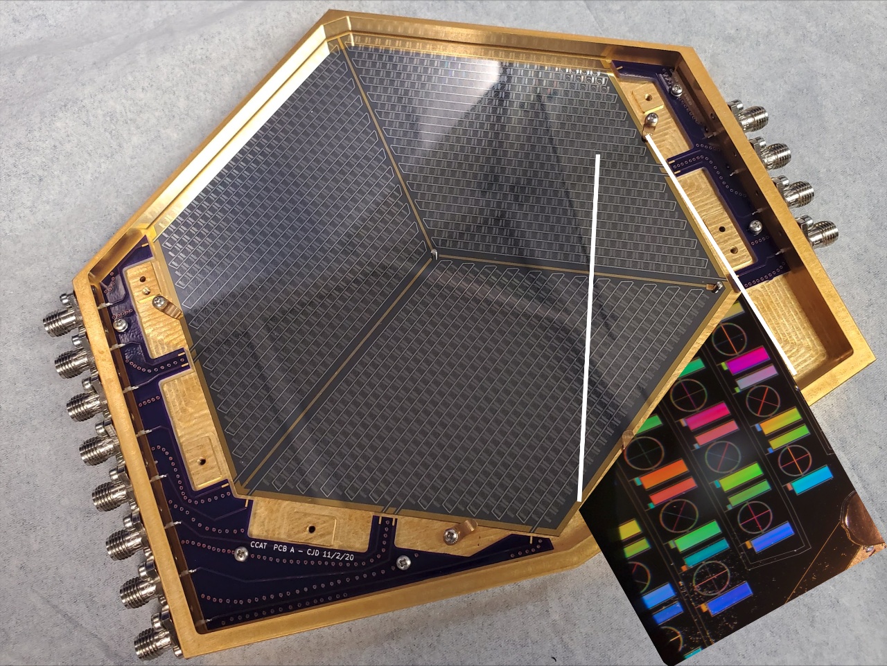
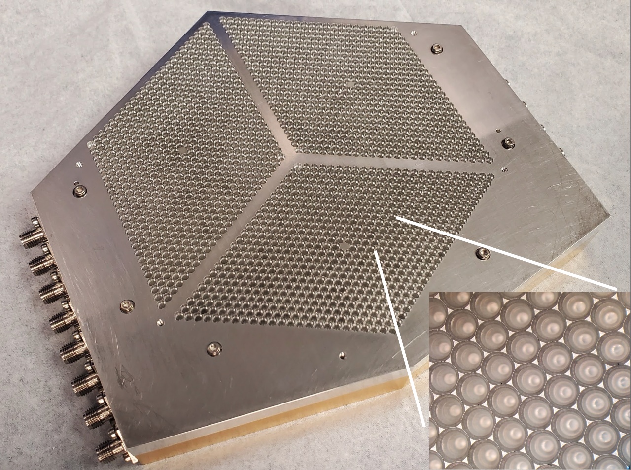
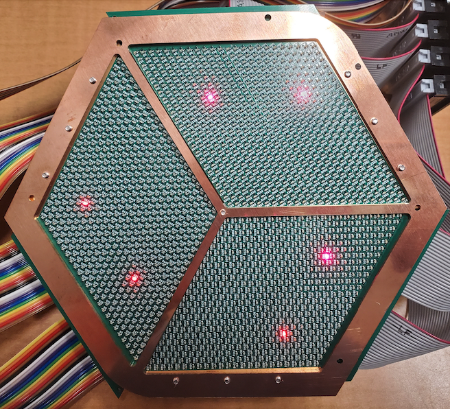
The mechanical design for the 280 GHz polarimetric MKID array package is described in duell/2020 . The array is fabricated on a 150 mm diameter wafer at National Institute of Standards and Technology (NIST Boulder), and uses pixel design based on TolTEC austermann/2018 but laid out in hexagonal close packing in three rhombuses for a total of 3,456 detectors over six RF feedlines (Figure 1). The superconducting material is TiN/Ti/TiN trilayer with a critical temperature of 1.1 K, used as both the inductor of the resonator and absorber that couples to light from the waveguides and feedhorns. The spline-profiled feedhorns with chokes are machined on aluminum with the Kern EVO CNC milling machine at ASU. The array is assembled onto the gold-plated aluminum base (Figure 1 left panel), aligned with two 1.5 mm diameter dowel pins, held down with four BeCu tabs, and aluminum-wirebonded to printed circuit boards (PCBs). To compensate for differential thermal contraction, the outer dowel pin hole on the array is elongated. There are 18 pogo pins placed on the three gaps separating the three rhombuses on the aluminum feedhorns to softly press the array against the base to prevent microphonics. The feedhorns are placed on the base with two other alignment pins, thereby aligning both the array and the feehorns to the base to m. The flatness across the feedhorn array is 13 m. Precision stand-offs set the space between the array and the chokes to be 110 m when cooled to 100 mK. Prior to assembly and testing with the MKID array, mechanical and cryogenic validations were done using a mechanical test array with the base and the feedhorns.
The array is cooled to a base temperature of 100 mK in a Bluefors dilution refrigerator (SD250), and read out with the second generation Reconfigurable Open Architecture Computing Hardware (ROACH-2) board and intermediate frequency (IF) electronics and firmware from Arizona State University (ASU) gordon/2016 . The six RF feedlines are tested one at a time using a pair of cold and warm readout lines with an RF switch system at 100 mK. Passive components in the RF chain include attenuators, DC blocks, and high-pass filters. The signal is amplified both at 4 K, by a low noise amplifier from ASU, and at room temperature, by a Mini-Circuits ZX60-43-S+. The low noise amplifier provides 30 dB of gain (with a noise temperature of 5 K) and the room temperature amplifier provides an additional 20 dB. The IF electronics include input and output variable attenuators that are adjusted to maximize the signal-to-noise ratio while maintaining linearity.
Various measurement and testbed tools are under active development. They include LED mappers (with components and the design from NIST) to measure the physical position mapping of the resonators, a broad frequency range cold load blackbody source for characterizing the detector responsivity, an IR source with polarizer and XY-stage for measuring beam and polarization efficiency, and a Fourier transform spectrometer for measuring the detector passband.
While fabrications of MKID arrays continue to improve, the resonator frequencies often deviate from the target frequencies due to imperfections, parasitic reactance, stray magnetic fields, etc. This leads to frequency collisions and degraded yield on MKID arrays. The LED mapper is a PCB with LEDs positioned to control illumination directly over the feedhorns, thereby allowing mapping between the physical position of the detectors and the frequencies of the resonators that respond to the LEDs. This mapping can then be used to fine-tune the resonator frequencies by lithographically trimming the interdigitated capacitors. This can reduce frequency collisions and hence the yield of the array, as demonstrated on a 127-resonator array at NIST liu/2017 . However, the LED trimming method has yet to be demonstrated on a large format MKID array with feedhorn coupling and choke structures that extend over the capacitors, which could potentially cause fringing fields affecting the resonators. Here we study the sensitivity of the resonators to the precise positioning of the feedhorns with chokes, by measuring the resonator frequency shifts due to removing and replacing the feedhorns over the array.
3 Method, Data, and Results
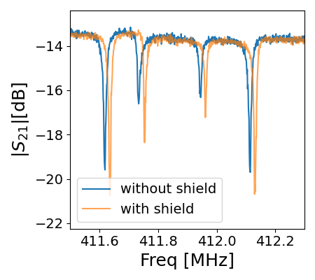
The primary data we use are the complex forward transmission through the feedline with resonators (), taken with the ROACH-2 over one of the six RF feedlines at a time:
where is the resonant frequency, is the measured resonator quality factor, and is the coupling quality factor for coupling to the RF feedline. The resonator quality factor includes , the internal quality factor , and any external loss quality factor :
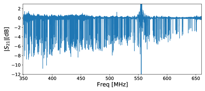
The magnitude of the complex forward transmission at 105 mK for one feedline is shown in Figure 2. The resonators trace circles in the complex plane, to which we can fit the resonator parameters in addition to fitting them in the magnitude space.
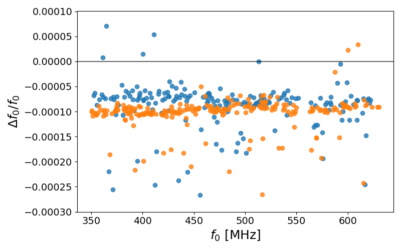
We present here the results from the data taken before and after removing and replacing the feedhorns over the array, and quantify the level of the shift in resonator frequencies, . The feedhorns are aligned to the base that holds the array with two pins with a precision better than 30 m. We test the level of frequency shift that can occur due to this precision. The LED mapper trimming procedure requires a post-fabrication process on the array, and hence it is crucial to maintain the repeatability of resonator frequencies, even after re-assembly of the array with the package, which may result in alignment shifts. We measure over two feedlines and find the means and the standard deviations to be and , as shown in Figure 3. The mean shift is partly due to the two datasets being taken at different temperatures, and the scatter is the important quantity. The scatter in fractional spacing can be improved from to from the LED mapper trimming process liu/2017 . Hence the fractional scatter due to re-assembly procedures is 5–10 smaller than that from the LED mapper trimming process. We repeat this test of removing and replacing the feedhorns one more time and find good consistency again after the re-assembly. We conclude that the shifts due to re-assembly of the array package are negligible. The LED mappers for the 280 GHz MKID array feedhorns are built (left panel of Figure 4), and we will soon proceed with the measurements and corrections.
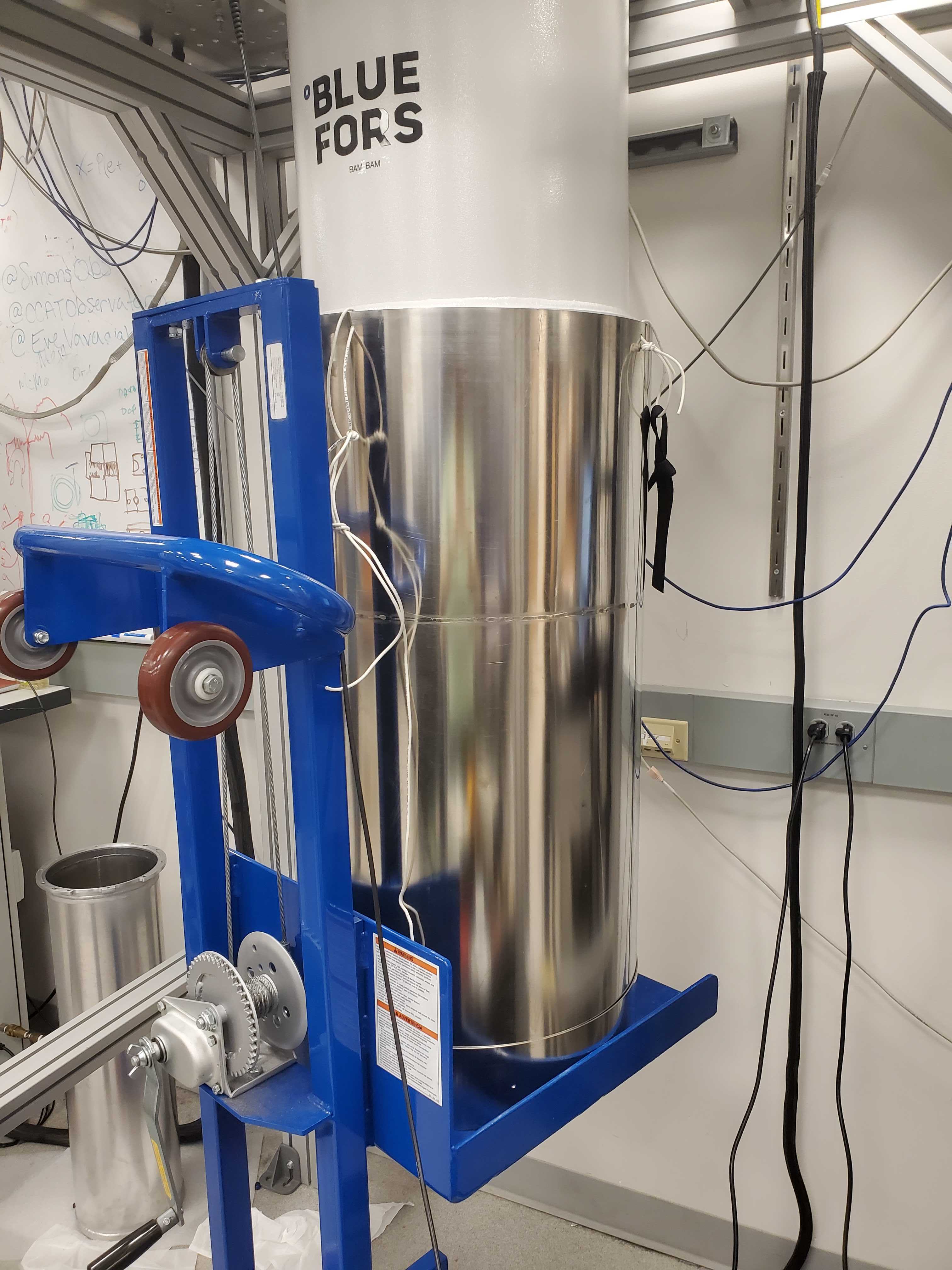
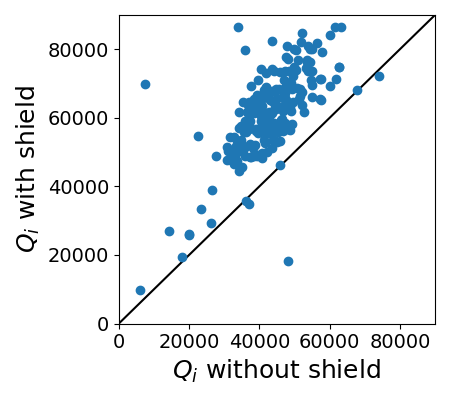
We also show the effect of magnetic shielding on the resonators in Figure 5, by comparing the data taken without an external magnetic shield with the data taken after placing the magnetic shield outside the 300 K shell of the cryostat and thermal cycling through the detector critical temperature. The cylindrical magnetic shield is 1.5 mm thick Mu-metal, 889 mm tall, 447 mm diameter with an opening at the top, and is placed such that the array sits centered inside the cylinder 520 mm below the opening (right panel of Figure 4). The measured shielding factor for static fields is 20 at this height. We find that using the magnetic shield leads to 1.4 times larger , while is , indicating the importance of magnetic shielding for the quality factors of these MKIDs. Ambient magnetic fields can get trapped in the MKID elements, suppressing local superconducting transitions in thin films, thereby increasing the number of quasiparticles and decreasing quality factors flanigan/2016 ; kutsuma/2018 . Further magnetic shielding studies with a Helmholtz coil are planned for the near future. For Prime-Cam, we expect a nominal magnetic shielding factor of 100 at the arrays based on simulations vavagiakis/2018b ; ali/2020 .
4 Conclusion
The characterization of the first 280 GHz MKID array for Prime-Cam is ongoing. We found that any resonator frequency shift due to the re-assembly process of the detector array package, in particular the alignment of the feedhorn array with the chokes that are close to the capacitors, is negligible compared to the effect of the LED mapper trimming process. We also showed that magnetically shielding the resonators can improve the quality factors and plan to quantify this in the near future. The LED position-frequency mapping and trimming process for the first 280 GHz array will soon take place, followed by a campaign of optical characterization work. Two more 280 GHz MKID arrays will be fabricated at NIST to fill one instrument module gudmundsson/2021 , and the possibility of using aluminum for the superconductor, and silicon-platelet feedhorns is being explored. Broadband instrument modules with 350 GHz and 850 GHz polarization-sensitive MKID arrays, and spectrometer instrument modules using MKID arrays coupled to Fabry-Perot interferometers are funded and in development. Testing and characterization of the first light receiver Mod-Cam with one instrument module is ongoing duell/2020 . The Prime-Cam cryostat is being machined and delivery is expected early 2022. Lastly, FYST is being constructed for first light with Mod-Cam in 2023.
Acknowledgements.
SKC acknowledges support from NSF award AST-2001866. MDN acknowledges support from NSF award AST-2117631. ZBH acknowledges support from a NASA Space Technology Graduate Research Opportunities Award. YL acknowledges support from KIC Postdoctoral Fellowship.References
- (1) CCAT-Prime collaboration, et al. arXiv e-prints, page arXiv:2107.10364, (2021).
- (2) P. A. R. Ade, et al. Phys. Rev. Lett., 127(15):151301, (2021).
- (3) D. Dutcher, et al. Phys. Rev. D, 104(2):022003, (2021).
- (4) Steve K. Choi, et al. JCAP, 2020(12):045, (2020).
- (5) Peter Ade, et al. JCAP, 2019(2):056, (2019).
- (6) Charles A. Hill, et al. volume 10708 of Society of Photo-Optical Instrumentation Engineers (SPIE) Conference Series, page 1070842, (2018).
- (7) S. K. Choi, et al. Journal of Low Temperature Physics, 199(3-4):1089–1097, (2020).
- (8) Heather McCarrick, et al. ApJ, 922(1):38, (2021).
- (9) J. Hubmayr, et al. Applied Physics Letters, 106(7):073505, (2015).
- (10) J. E. Austermann, et al. Journal of Low Temperature Physics, 193(3-4):120–127, (2018).
- (11) Cody J. Duell, et al. volume 11453 of Society of Photo-Optical Instrumentation Engineers (SPIE) Conference Series, page 114531F, (2020).
- (12) Samuel Gordon, et al. Journal of Astronomical Instrumentation, 5(4):1641003, (2016).
- (13) X. Liu, et al. arXiv e-prints, page arXiv:1711.07914, (2017).
- (14) D. Flanigan, et al. Applied Physics Letters, 109(14):143503, (2016).
- (15) Hiroki Kutsuma, et al. Journal of Low Temperature Physics, 193(3-4):203–208, (2018).
- (16) E. M. Vavagiakis, et al. Journal of Low Temperature Physics, 193(3-4):288–297, (2018).
- (17) Aamir M. Ali, et al. Journal of Low Temperature Physics, 200(5-6):461–471, (2020).
- (18) Jon E. Gudmundsson, et al. Appl. Opt., 60(4):823, (2021).