Extremely brilliant crystal-based light sources
Abstract
Brilliance of novel gamma-ray Crystal-based Light Sources (CLS) that can be constructed through exposure of oriented crystals to beams of ultrarelativistic charged particles is calculated basing on the atomistic scale numerical modeling of the channeling process. In an exemplary case study, the brilliance of radiation emitted in a diamond-based Crystalline Undulator LS by a 10 GeV positron beam available at present at the SLAC facility is computed. Intesity of CU radiation in the photon energy range MeV, which is inaccessible to conventional synchrotrons, undulators and XFELs, greatly exceeds that of laser-Compton scattering LSs and can be higher than predicted in the Gamma Factory proposal to CERN. Construction of novel CLSs is a challenging task which constitutes a highly interdisciplinary field entangling a broad range of correlated activities. CLSs provide a low-cost altenative to conventional LSs and have enomorous number of applications.
Development of light sources (LS) operational at wavelengths well below one angstrom (corresponding photon energies keV) is a challenging goal of modern physics. Sub-angstrom wavelength, ultrahigh brilliance, tunable LSs will have a broad range of exciting potential cutting-edge applications. These applications include exploring elementary particles, probing nuclear structures and photonuclear physics, and examining quantum processes, which rely heavily on gamma-ray sources in the MeV to GeV range KorolSolovyov:EPJD_CLS_2020 ; Zhu-EtAl:ScieAdv_vol6_eaaz7240_2020 ; NextGenerationGammaRayLS2020 . Modern X-ray Free-Electron-Laser (XFEL) can generate X-rays with wavelengths Å Seddon-EtAl_RepProgPhys_v80_115901_720_2017 ; Doerr-EtAl_NatureMethods_v15_p33_2018 ; SwissFEL_ApplScie_v7_720_2017 ; Bostedt-EtAl_RMP_v88_015007_2016 . Existing synchrotron facilities provide radiation of shorter wavelengths but orders of magnitude less intensive Couprie:JElSpectRelPhen_v196_p3_2014 ; Tavares-EtAl:JSynchrRad_v21_p862_2014 ; YabashiTanaka_NaturePhotonics_v11_p12_2017 . Therefore, to create a powerful LS in the range Å new approaches and technologies are needed.
In recent years KorolSolovyov:EPJD_CLS_2020 ; KorolSolovyov:EPJD_Colloquium_2021 significant efforts of the research and technological communities have been devoted to design and practical realization of novel gamma-ray Crystal-based LSs (CLS) that can be set up by exposing oriented crystals to beams of ultrarelativistic positrons or electrons. Manufacturing of CLSs is a subject of the current European Horizon-2020 project ’N-LIGHT’ N-Light and upcoming Horizon-EIC-2021 project TECHNO-CLS. Construction of a CLS is a challenging technological task, which requires a highly interdisciplinary approach combining development of technologies for crystalline sample preparation (engaging material science, nanotechnology, acoustics, solid state physics) together with a detailed experimental programme (for CLS characterization, design of incident particle beams, experimental characterization of the radiation emitted) as well as theoretical analysis and advanced computational modelling for the visualisation and characterisation of CLSs based on an atomistic level description.
This Letter provides accurate predictions for the brilliance of a Crystalline Undulator (CU) ChannelingBook2014 LS on the basis of all-atom molecular dynamics simulations of relativistic particles channeling and radiation in oriented crystals. The exemplary case study presented below shows that using currently available positron beam it is realistic to achieve the brilliance of radiation emitted in the photon energy range MeV that exceed brilliance of the laser-Compton scattering LSs Rehman_EtAl_ANE_v105_p150_2017 ; Kraemer_EtAl-ScieRep_v8_p139_2018 ; Krafft-Priebe:RevAccScieTechnol_vol3_p147_2010 ; Sei-EtAl:ApplSci_vol10_p1418_2020 ; NextGenerationGammaRayLS2020 ; Wu-EtAl:PRL_vol96_224801_2006 . and of the LS well as of the predicted in the Gamma Factory proposal for CERN Krasny:2018xxv ; GammaFactory:Letter_of_intent2019 .
Numerical modeling of the channeling and related phenomena beyond the continuous potential framework has been carried out by means of the multi-purpose computer package MBN Explorer MBN_Explorer_2012 ; MBN_ChannelingPaper_2013 ; MBNExplorer_Book and a supplementary special multitask software toolkit MBN Studio MBN_Studio_2019 . A special module of MBN Explorer allows one to simulate the motion of relativistic projectiles along with dynamical simulations of the environment MBN_ChannelingPaper_2013 . The uniqueness of the computation algorithm is that it accounts for the interaction of projectiles with all atoms of the environment thus making it free of simplifying model assumptions. In addition, a variety of interatomic potentials implemented facilitates rigorous simulations of various media, a crystalline one in particular. Overview of the results on channeling and radiation of charged particles in oriented linear, bent and periodically bent crystals simulated by means of MBN Explorer and MBN Studio can be found in KorolSolovyov:EPJD_CLS_2020 ; KorolSolovyov:EPJD_Colloquium_2021 ; ChannelingBook2014 ; MBNExplorer_Book .
In Ref. KorolSolovyov:EPJD_CLS_2020 brilliance of radiation emitted in the photon energy range - MeV in a CU-LS has been estimated using the model based the continuous interplanar potential concept Lindhard and utilizing the phenomenological approach to describe the dechanneling process. The model has allowed one to establish optimal parameters of a periodically bent crystal (these include crystal thickness in the direction of beam, - the -direction, bending amplitude and period ) that ensure the highest values of brilliance of the CU-LS for a positron beam of given energy , transverse beam sizes and angular divergence .
The results presented in this Letter have been obtained for a GeV positron beam propagating through an oriented periodically bent diamond (110) crystal. The beam sizes and divergence used in the simulations are microns and rad, respectively. They correspond to normalized emittance m-rad and are within the ranges indicated for the FACET-II beam available at the SLAC facility FACETII_Conceptual_Design_Rep-2015 (see Supplemental Material (SM)).
the relativistic Lorentz factor Set (Å) (m) (mm) (MeV) (I) 20.9 85 85 7.06 2.0 (II) 5.3 38 180 6.84 10.0
The values of bending amplitude , and period as well as the number of periods and the crystal thickness used in the simulations are listed in Table 1. Within the framework of the model approach KorolSolovyov:EPJD_CLS_2020 it has been established that each set of these parameters provides the maximum brilliance of the CU-LS radiation emitted in the forward direction at the fundamental harmonic energy indicated in the last column. The frequency is calculated as follows
| (1) |
where is the relativistic Lorentz factor, stands for an undulator parameter and .
It is important to mention that the values of , and indicated in the table are accessible by means of existing modern technologies. Construction of novel gamma-ray CLSs is a challenging task involving a broad range of correlated research and technological activities. One of the key technological task concerns manufacturing of crystals of different desired geometry. High quality of the undulator material is essential for achieving strong effects in the emission spectra. A systematic review of different technologies exploited for manufacturing of crystals of different type, geometry, size, quality, etc. one finds in Refs. KorolSolovyov:EPJD_CLS_2020 ; KorolSolovyov:EPJD_Colloquium_2021 . A brief summary is presented in SM.
To simulate the trajectories of the beam particles in the crystalline medium, the -axis was chosen along the axial direction. This choice ensures that a sufficiently big fraction of the incident beam is accepted in the channeling mode at the crystal entrance. For a Gaussian beam this fraction can be estimated as where stands for Lindhard’s critical angle. Using eV for the interplanar potential depth in diamond(110) one calculates rad that exceeds by a factor of two the divergence rad. The beam divergence rad along the transverse direction is much smaller than the natural emission angle rad. As a result, one can expect that big fraction of radiation emitted by the channeling particles will be collected within the cone centered along the incident beam.
The simulations performed aimed at providing accurate quantitative data on the brilliance of a CU-LS. Brilliance, , of a LS is proportional to the number of photons of frequency within the interval emitted in the cone per unit time interval, unit source area, unit solid angle and per a bandwidth (BW) SchmueserBook . To calculate this quantity it is necessary to know the beam electric current , its transverse sizes and divergences as well as the divergence angle and the ’size’ of the photon beam. Explicit expression for reads
| (2) |
Here is the electric current (in amperes) of the beam of particles, is the elementary charge. The quantities stand for the total emittance of the photon source in the transverse directions. Commonly, brilliance is measured in . To achieve this in (2) one substitutes in amperes, in millimeters, and in milliradians. If one uses the peak value of the current, , then the corresponding quantity is called peak brilliance, .
The number of photons within the BW is proportional to the spectral distribution of the energy radiated per particle in the solid angle (the emission cone is assumed to be small, ): . Using this relation one writes the brilliance in terms of the spectral distribution:
| (3) |
In the simulations, the spectral distribution has been calculated for each trajectory simulated ( with the total number of trajectories ). Initial conditions at the crystal entrance (the transverse coordinates and velocities) have been generated using the normal distributions with the deviations and quoted above. The resulting spectral distribution used to calculate the brilliance (3) has been obtained by averaging the individual spectra: . The sum is carried out over all simulated trajectories, and thus, its takes into account the contribution of the channeling segments as well as of those corresponding to the non-channeling regime. More details on the simulation procedure as well on the formalism behind it one finds in the review paper KorolSolovyov:EPJD_Colloquium_2021 .
As a case study below the emission of radiation from the CU with the parameters labeled as ’Set (I) in Table 1 is considered in more detail.
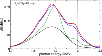
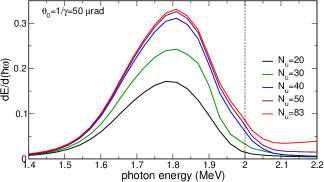
Figure 1 presents the spectral distribution of radiation emitted within the narrow cone rad (left) and the wider one rad (right). The calculations were performed for different number of undulator periods as indicated in the common legend shown in the right graph.
Several features of the computed spectra are to be noted. First, all peaks are red-shifted from the estimate MeV that follows from Eq. (1). Second, for large number of periods the spectrum becomes virtually independent on .
To provide an explanation to both of these features we first note that in the vicinity of maximum the emission spectrum is mainly formed by the particles, which move in the channeling mode through the whole crystal (see Figure S1 in SM). Therefore, the evolution of the spectrum is related, to a great extent, to the dynamics of channeling particles in the course of their propagation through the crystalline medium. Eq. (1) describes accurately the on-axis frequency of the fundamental harmonic in an ideal planar undulator, in which a particle moves along a perfect cosine trajectory . In a CU, a channeling particle experiences (i) channeling oscillations while moving along a periodically bent centerline, and (ii) stochastic motion along the axis due to the multiple scattering from crystal constituents. The channeling oscillations lead to the following modification of the undulator parameter: .Here with and being the amplitude and period of the channeling oscillations. In the case of positron channeling, assuming harmonicity of the oscillations, one carries out averaging over the allowed values of and finds ChannelingBook2014 . For GeV in diamond(110) ( eV) this results in . The stochastic motion along the axis results in a gradual increase in the rms scattering angle with the penetration distance . Hence, the motion of the particle is not restricted to the plane and its emission within the cone centered along the incident beam direction becomes off-axis. As a result, the denominator of the fraction in (1) increases, , leading to the decrease in the fundamental harmonic frequency. The increase in the rms scattering angle leads to the saturation of the emission spectrum with the crystal thickness. Indeed, taking into account that an ultra-relativistic particle radiates, predominantly, within the cone along its instant velocity, the emission within the cone along the axis becomes negligibly small at the penetration distances when the relation becomes valid. Here the term accounts for the beam divergence at the crystal entrance. The spectrum saturates at .
The increase in the multiple scattering angle is also the main reason for a suppression of the simulated intensity as compared to the ideal undulator, see Fig. S2 in SM.
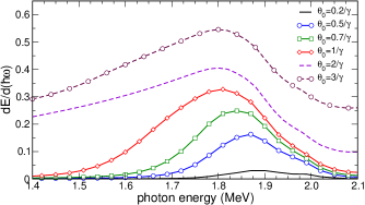
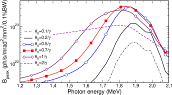
The CU radiation spectra calculated for different emission cones, , are presented in the left graph of Fig. 2. All curves correspond to the crystal length mm (). These data supplemented with the aforementioned values for the beam size, divergence and peak current allow one to calculate the peak brilliance of the CU-LS, Eq. (3). The results of calculations are shown in Fig. 2 right. It is seen that in contrast to , which is an increasing function of the emission cone, the peak brilliance is a non-monotonous function due to the presence of the terms proportional to in the total emittance that enter the denominators in Eqs. (2) and (3). In the case study considered here the maximum value photons/s/mrad2mm2/0.1 % BW is achieved at MeV for rad.
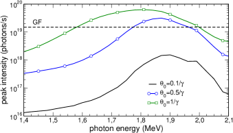
The product on the right-hand side of Eq. (1) defines the number of photons per unit time interval (intensity) emitted in the solid angle and frequency interval . Using the peak current kA one calculates the peak intensity achievable in the CU with given bending parameters exposed to the FACET-II beam. Figure 3 shows the corresponding dependences calculated for for the BW and for several emission cones as indicated.
It is instructive to compare the CU-LS intensity with the intensity predicted in the Gamma Factory (GF) proposal for CERN Krasny:2018xxv ; GammaFactory:Letter_of_intent2019 . The latter discusses a concept of the LS based on the resonant absorption of laser photons by ultra-relativistic ions. It is expected that the intensity of the GF LS will be orders of magnitude higher that the presently operating laser-Compton LSs aiming at the value of photons/s in the gamma-ray domain above 1 MeV. The quoted value of the intensity refers to the average beam current. To calculate the corresponding peak value one multiplies by a factor , which is the ratio of the bunch spacing (100 ns) to the bunch length (0.64 ns). The dashed line in Fig. 3 indicates the peak intensity of the GF LS equal to photons/s. To be noted is that for the bending amplitude and period considered the intensity of the CU-LS in the vicinity of its first harmonic emitted within the cones greater than rad exceeds the the peak value .
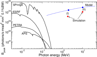
Figure 4 compares peak brilliance of several operational synchrotron radiation facilities with that achievable by means of the diamond-based CU exposed to the FACET-II positron beam. The dashed line shows the results of the model calculations KorolSolovyov:EPJD_CLS_2020 that have provided, for each photon energy , the highest value of by scanning through the ranges of and . Symbols show the values of obtained for Sets (I) and (II) of the parameters indicated in Table 1: the results of model calculations estimations (circles) are to be compared with the results of the accurate numerical simulations (diamonds).
The results of accurate numerical simulations presented in this Letter refer to the specific case study of the radiation emission by a 10 GeV positron beam (with the transverse size and divergence indicated in Ref. FACETII_Conceptual_Design_Rep-2015 ) channeling in an oriented periodically bent diamond (110) crystal. The parameters indicated in Table 1 maximize the peak brilliance of radiation in the vicinity of the MeV (Set I) and 10 MeV (Set II) as it has been estimated by means of the model approach KorolSolovyov:EPJD_CLS_2020 . The simulations demonstrated that the peak brilliance of the CU-LS is comparable to or even higher than that achievable in conventional synchrotrons in the much lower photon energy range. The intensity of radiation exceeds the values predicted in the GF proposal for CERN.
By tuning the bending amplitude and period one can maximize brilliance for given parameters of a positron beam and/or chosen type of a crystalline medium. As a result extremely high values of brilliance can be achieved in the photon energy range MeV by currently available (or planned to be available in near future) positron beams KorolSolovyov:EPJD_CLS_2020 . For each set of the input parameters (beam energy and emittance, bending amplitude and period, crystal type and thickness, detector aperture etc.) to provide accurate data on the brilliance from a CLS rigorous numerical simulations, similar to those presented in this Letter, must be carried out. When doing this, the results of the model approach can be used as the initial estimates of the the ranges of the parameters to be used in the simulations.
It is worth mentioning that the size and the cost of CLSs are orders of magnitude less than those of modern LSs based on the permanent magnets. This opens many practical possibilities for the efficient generation of gamma-rays with various intensities and in various ranges of wavelength by means of the CLSs on the existing and newly constructed beam-lines.
The work was supported in part by the DFG Grant (Project No. 413220201) and by the H2020 RISE-NLIGHT project (GA 872196). We acknowledge the Frankfurt Center for Scientific Computing (CSC) for providing computer facilities.
References
- (1) A. V. Korol and A. V. Solov’yov. Crystal-based intensive gamma-ray light sources. Europ. Phys. J. D 74, 201 (2020).
- (2) Xing-Long Zhu, Min Chen, Su-Ming Weng, Tong-Pu Yu, Wei-Min Wang, Feng He, Zheng-Ming Sheng, Paul McKenna, Dino A. Jaroszynski, and Jie Zhang. Extremely brilliant GeV -rays from a two-stage laser-plasma accelerator. Science Advances 6, eaaz7240 (2020).
- (3) C. R. Howell, M.W. Ahmed, A. Afanasev, D. Alesini, J. R. M. Annand, et al. International Workshop on Next Generation Gamma-Ray Source. arXiv preprint arXiv:2012.10843 (2020).
- (4) Y.K. Wu, N.A. Vinokurov, S. Mikhailov, J. Li, and V. Popov: High-Gain Lasing and Polarization Switch with a Distributed Optical-Klystron Free-Electron Laser. Phys. Rev. Lett. 96, 224801 (2006).
- (5) A. Doerr. The new XFELs. Nature Meth. 13, 33 (2018).
- (6) E. A. Seddon, J. A. Clarke, D. J. Dunning, C. Masciovecchio, C. J. Milne, F. Parmigiani, D. Rugg, J. C. H. Spence, N. R. Thompson, K. Ueda, S. M. Vinko, J. S. Wark, and E. Wurth. Short-wavelength free-electron laser sources and science: a review. Rep. Prog. Phys. 80, 115901 (2017).
- (7) Ch. J. Milne, Th. Schietinger, M. Aiba, A. Alarcon, J. Alex, et al. SwissFEL: The Swiss X-ray free electron laser. Appl. Scie. 7, 720 (2017).
- (8) Ch. Bostedt, S. Boutet, D. M. Fritz, Z. Huang, H. J. Lee, H. T. Lemke, A. Robert, W. F. Schlotter, J. J. Turner, G. J. Williams. Linac coherent light source: The first five years. Rev. Mod. Phys. 88, 015007 (2016).
- (9) M.E. Couprie. New generation of light sources: Present and future. J. Electr. Spectrosc. Rel. Phenom. 196, 3 (2014).
- (10) P. F. Tavares, S. C. Leemann, M. Sjöström, and Å. Andersson. The MAX IV storage ring project. J. Synchrotron Rad. 21, 862 (2014).
- (11) M. Yabashi and H. Tanaka. The next ten years of X-ray science. Nat. Photonics 11, 12 (2017).
- (12) A. V. Korol and A. V. Solov’yov. All-atom relativistic molecular dynamics simulations of channeling and radiation processes in oriented crystals. Europ. Phys. J. D 75, 207 (2021).
- (13) http://www.mbnresearch.com/N-Light/main
- (14) A. V. Korol, A. V. Solov’yov, and W. Greiner, Channeling and Radiation in Periodically Bent Crystals, Second ed., Springer-Verlag, Berlin, Heidelberg, 2014.
- (15) Haseeb ur Rehman, Jiyoung Lee, and Yonghee Kim. Optimization of the laser-Compton scattering spectrum for the transmutation of high-toxicity and long-living nuclear waste. Ann. Nucl. Energy 105, 150 (2017).
- (16) J. M. Krämer, A. Jochmann, M. Budde, M. Bussmann, J. P. Couperus et al. Making spectral shape measurements in inverse Compton scattering a tool for advanced diagnostic applications. Scie. Reports 8, 139 (2018).
- (17) G.A. Krafft and G. Priebe. Compton sources of electromagnetic radiation. Rev. Accelerator Scie. Technol. 3, 147 (2010).
- (18) Norihiro Sei, Hiroshi Ogawa, and QiKa Jia. Multiple-Collision Free-Electron Laser Compton Backscattering for a High-Yield Gamma-Ray Source. Appl. Sci. 10, 1418 (2020).
- (19) M. Krasny. The Gamma Factory proposal for CERN. CERN Proc. 1, 249 (2018).
- (20) M. W. Krasny, A. Martens, and Y. Dutheil. Gamma factory proof-of-principle experiment: Letter of intent. CERN-SPSC-2019-031/SPSC-I-253, 25/09/2019 (http://cds.cern.ch/record/2690736/files/SPSC-I-253.pdf).
- (21) I. A. Solov’yov, A. V. Yakubovich, P. V. Nikolaev, I. Volkovets, and A. V. Solov’yov. MesoBioNano Explorer – A universal program for multiscale computer simulations of complex molecular structure and dynamics.. J. Comp. Phys. 33, 2412 (2012).
- (22) G. B. Sushko, V. G. Bezchastnov, I. A. Solov’yov, A. V. Korol, W. Greiner, and A. V. Solov’yov, Simulation of ultra-relativistic electrons and positrons channeling in crystals with MBN Explorer. J. Comp. Phys. 252, 404 (2013).
- (23) I. A. Solov’yov, A. V. Korol, and A. V. Solov’yov, Multiscale Modeling of Complex Molecular Structure and Dynamics with MBN Explorer. Springer International Publishing, Cham, Switzerland (2017).
- (24) G. B. Sushko, I. A. Solov’yov, and A. V. Solov’yov, Modeling MesoBioNano systems with MBN Studio made easy. J. Mol. Graph. Model. 88, 247 (2019).
- (25) J. Lindhard. Influence of crystal lattice on motion of energetic charged particles. K. Dan. Vidensk. Selsk. Mat. Fys. Medd. 34, 1-64 (1965).
- (26) SLAC Site Office: Preliminary Conceptual Design Report for the FACET-II Project at SLAC National Accelerator Laboratory. Report SLAC-R-1067, SLAC (2015).
- (27) Schmüser, P., Dohlus, M. and Rossbach, J. Ultraviolet and Soft X-Ray Free-Electron Lasers. Springer, Berlin/Heidelberg (2008).