Ultra-relativistic electron beams deflection by quasi-mosaic crystals
Abstract
This paper provides an explanation of the key effects behind the deflection of ultra-relativistic electron beams by means of oriented ‘quasi-mosaic’ Bent Crystals (qmBC). It is demonstrated that accounting for specific geometry of the qmBC and its orientation with respect to a collimated electron beam, its size and emittance is essential for an accurate quantitative description of experimental results on the beam deflection by such crystals. In an exemplary case study a detailed analysis of the recent experiment at the SLAC facility is presented. The methodology developed has enabled to understand the peculiarities in the measured distributions of the deflected electrons. Also, this achievement constitutes an important progress in the efforts towards the practical realization of novel gamma-ray crystal-based light sources and puts new challenges for the theory and experiment in this research area.
pacs:
61.85.+p, 41.60.-m, 41.75.Ht, 02.70.Uu, 07.85.FvIn recent years significant efforts of the research and technological communities have been devoted to design and practical realization of novel gamma-ray Crystal-based Light Sources (CLS) that can be set up by exposing oriented linear, bent or periodically bent crystals to beams of ultrarelativistic positrons or electrons KorolSolovyovCLS2020 ; KorolSolovyovColloquium2021 . Brilliance of radiation emitted in a crystalline undulator LS by available beams in the photon energy range - MeV, being inaccessible to conventional synchrotrons, undulators and XFELs, greatly exceeds that of laser-Compton scattering LSs and is higher than predicted in the Gamma Factory proposal to CERN Krasny2018 . Manufacturing of CLSs will have significant impact on many research areas in physics, chemistry, biology, material science, technology and medicine, being a subject of current European projects ’N-LIGHT’ NLight and TECHNO-CLS TECHNOCLS .
So far oriented crystals exposed to beams of charged particles have been already utilised in a number of applications for beams manipulation, such as steering, bending, extraction and focusing, see KorolSolovyovColloquium2021 ; ChannelingBook2014 and references therein. These and other newly emerging applications in this research area require high quality crystals (bent or periodically bent) and collimated beams of charged ultrarelativistic particles of different energies.
Construction of novel CLSs is a challenging task involving a broad range of correlated research and technological activities KorolSolovyovCLS2020 ; KorolSolovyovColloquium2021 . During the last decade a number of papers published in high-impact journals MazzolariPRL2014 ; Wienands2015 ; BandieraPRL2015 ; BandieraPRL2013 ; MazzolariEPJC2018 ; SytovEPJC2016 ; WistisenPRAB2016 on channeling and channeling radiation experiments with bent crystals at different facilities (SLAC, CERN, MAMI). This paper reports on the important progress in this field providing an explanation of the key effects arising by deflection of ultrarelativistic electron and positron beams by means of oriented ‘quasi-mosaic’ Bent Crystals (qmBC). It is demonstrated that account for specific geometry of qmBC and its orientation with respect to a collimated beam of projectile particles, the beam size and emittance is essential for the quantitative description of the experimental results on the beam deflection by such crystals.
Manufacturing of crystals of different desired geometry is an important technological task in the context of their applications in the gamma-ray CLSs and the aforementioned experiments. The systematic review of different technologies exploited for manufacturing of crystals of different type, geometry, size, quality, etc is given in ChannelingBook2014 ; KorolSolovyovCLS2020 ; KorolSolovyovColloquium2021 . A short summary of several relevant approaches that have been utilized to produce bent crystals is provided in Supplemental Material (SM).
The high-quality qmBCs structures with desirable and fully controllable parameters have been manufactured for the aforementioned channeling experiments by the following means GuidiJPD2009 ; CamattariEtAl2015 ; MazzolariEtAlEPJCv882018 . When a moment of force is applied to a crystalline material, some secondary curvatures may arise within the solid Lekhnitskii1981 . A well known secondary deformation is the anticlastic curvature with radius that occurs in a medium subjected to two moments. In particular, it occurs in the perpendicular direction with respect to the primary curvature. When the two curvatures are combined, the deformed crystal acquires the shape of a saddle. In contrast to an amorphous medium physical properties of crystals may be strongly anisotropic. Another type of the deformation caused by anisotropic effects is the ‘quasi-mosaic’ (QM) curvature SumbaevJETP1957 ; IvanovJETPLett2005 . QM bent crystals belong to a class of bent crystals featuring two curvatures of two orthogonal crystallographic planes.
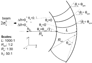
In order to understand the effects arising during channeling of charged particles through qmBC one should consider the geometry of such a crystal and its orientation with respect to an incident beam. This geometry is shown in Fig. 1. For the sake of clarity the case of planar channeling is addressed below.
Consider a crystal whose planes, which are parallel to the plane, experience anticlastic bending with the curvature radius . The center of the curvature lies on the axis, which runs through the crystal center. The QM bending deforms the crystal planes parallel to the plane. In what follows it is assumed that and the QM bending radius greatly exceed the crystal thickness . These conditions were met for the qmBC samples used in the experiments MazzolariPRL2014 ; Wienands2015 ; BandieraPRL2015 ; BandieraPRL2013 ; MazzolariEPJC2018 ; SytovEPJC2016 ; WistisenPRAB2016 . The QM bending angle is defined as follows
| (1) |
To start with, let us assume an ideally collimated narrow beam (i.e. that of zero divergence and zero beam size in the direction, ) incident on the crystal along the direction. For a planar channeling the beam size and divergence in the direction do not play important role and thus are not considered below.
At the crystal entrance, the angle between the beam direction and a tangent line to the QM bent plane depends on the beam displacement along the -axis:
| (2) |
where with
| (3) |
being the displacement for which the entrance angle , i.e. the tangent line is parallel to the axis.
A probability of a particle to be accepted into the channeling mode becomes significant if does not exceed Lindhard’s critical angle . Then, using (2) one finds the maximum value of
| (4) |
so that the channeling condition is met for the particles with within the interval .
At the crystal exit, the angle between the tangent line and the beam direction is related to via
| (5) |
Hence, the projectiles that are accepted at and channel through the whole crystal are deflected by the angle lying within the interval .
The particles that enter having can experience either volume capture or volume reflection TaratinVorobievPLA1986 ; TaratinVorobievPLA1987 in the crystal. The geometry analysis for these regimes is given in SM. The particles that enter with are neither accepted nor experience the volume reflection but experience multiple scattering which becomes closer to the scattering in the amorphous medium as increases.
Consider now a Gaussian beam, with width and divergence , that is incident on the crystal being centered at . For a beam centered at most of its particles enter the crystal having the transverse coordinates lying within the interval from to and the corresponding incident angles . Therefore, the distribution of deflected particles becomes a superposition of different propagation scenarios discussed above.
Below in the paper we demonstrate that it is important to know the values of and as well as of quite accurately to be able to interprete results of the experiments on beam propagation through oriented qmBC crystals.
In what follows we focus on the analysis of the experiment at SLAC Wienands2015 , although the physics discussed and the conclusions drawn are applicable to other aforementioned experiments with oriented qmBC. In the experiment, a 60 m thick Si(111) qmBC was exposed to a 6.3 GeV electron beam. To deduce the values of and one can rely on the following description provided in the cited paper: (i) ”…a beam width of m (1) in the vertical and horizontal plane”, and (ii) ”The beam divergence was inferred …to be less than 10 rad”. The QM bending radius of the (111) planes was quoted as cm. It was mentioned that some measures had been taken ”to reduce the anticlastic deformation” although the explicit value of was not indicated. Indirectly, one can estimate basing on the data presented in GuidiJPD2009 . This paper, cited in Ref. Wienands2015 , discusses the QM bending of Si(211), i.e. it refers to a different geometry in which the (111) planes experience the anticlastic bending rather than the QM one. For this geometry the value cm on the centre of the sample was measured. In our simulations we considered as a parameter varied within the interval cm. Using the aforementioned value of in (1) one finds rad. Fixing and taking into account that for a GeV electron Lindhard’s critical angle is rad Wienands2015 one calculates and the maximum displacement .
Numerical modeling of the channeling and related phenomena beyond the continuous potential framework can be carried out by means of the multi-purpose software package MBN Explorer MBNExplorer2012 ; MBNChannelingPaper2013 ; MBNExplorerBook and a supplementary special multitask software toolkit MBN Studio MBNStudio2019 . The MBN Explorer was originally developed as a universal computer program to allow multiscale simulations of structure and dynamics of molecular systems.
MBN Explorer simulates the motion of relativistic projectiles along with dynamical simulations of the crystalline environment MBNChannelingPaper2013 . The computation accounts for the interaction of projectiles with separate atoms of the environment, whereas a variety of interatomic potentials implemented supports rigorous simulations of various media. Overview of the results on channeling and radiation of charged particles in inear, bent and periodically bent crystals simulated by means of MBN Explorer can be found in KorolSolovyovCLS2020 ; KorolSolovyovColloquium2021 ; ChannelingBook2014 ; MBNExplorerBook .
To model propagation of particles through qmBCs further development of the algorithm for the atomistic simulations of the crystalline media has been performed in this work. The implemented algorithm enabled simulations of a qmBC defined through a transformation of the unperturbed crystalline medium by three curvatures (primary, anticlastic and QM), positioning of the qmBC with respect to the beam direction and the relativistic molecular dynamics in such environment. The results reported below have been obtained by means of this newly implemented algorithm.
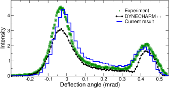
The main outcome of numerical analysis carried out in this Letter in connection with the SLAC experiment is shown in Figure 2, which compares the current simulations with the experimentally measured intensity of the deflected electron beam as well as with the result of the DYNECHARM++ simulations. The latter intensities were obtained by digitalizing the data, which are presented in arbitrary units in Fig. 3 in Wienands2015 , followed by the background (ca 1.4 a.u.) subtraction. The resulting experimental values were rescaled to provide the unit area within the interval mrad of the deflection angle. The ratio experiment-to-DYNECHARM++ was kept as in the original figure.
The simulated and measured angular distributions have the characteristic pattern of the two well pronounced peaks interlinked by an intermediate region. The left peak in the vicinity of describes a fraction of particles propagating though the qmBC in the forward direction. These particles experience multiple scattering resulting in broadening of the initial distribution of the beam particles. Small shift of the peak towards negative angles is due to the volume reflection of the particles from the bent planes. As discussed in SM this effect becomes more pronounced at the entrance points within the region . The right peak is formed by the particles accepted to the channeling regime at the entrance and deflected to the angle according to Eq. (5). Our simulations have shown that the position of the channeling peak is determined by the value corresponding to the beam center at the entrance point and the width of the peak is determined by the distribution of for the particles of the beam and by Lindhard’s angle. The peak is also influenced by the dechanneling process that is responsible for the formation of the distribution of the deflected particles in the region between the two peaks.
As mentioned, the angular distribution is very sensitive to the choice of the beam size , bending radius and the entrance coordinate . The current simulations presented in Fig. 2 correspond to a particular set of these parameters: m, cm and m. It has been established that these values provide close agreement with the experimentally measured distribution. We noted that in Ref. Wienands2015 the exact value of has been specified whereas the values of and as well as their impact on the profile of the distribution have not been mentioned at all. Same refers to the results of the DYNECHARM++ simulations.
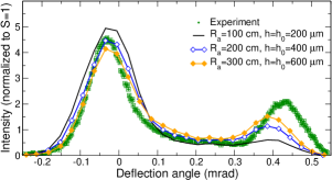
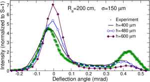
Figures 3 and 4 illustrate the impact of variation of , and on the the angular distribution. The symbols with error bars stand for the experimental data obtained as described above.
Figure 3 shows the distribution for a beam with m incident on the crystal bent with different anticlastic radius as indicated. In the left panel, each simulation refers to the beam centered at and thus most of the accepted particles are deflected by the angle resulting in the channeling peak centered at about 0.40 mrad, which is less than in the experiment (ca 0.44 mrad). The peak intensity increases with in accordance with the geometrical arguments discussed above. Indeed, for cm the maximum displacement m is nearly two times less than resulting in a small fraction of the accepted particles. Since (see Eq. (4) and Fig. S2 in SM) then for cm the value of exceeds leading to the higher intensity. The qmBC geometry provides also a qualitative explanation of the changes occurring to the left peak. For the smallest radius, the inequality suggests that large number of particles enters the crystal having the transverse coordinate (i) larger than , and (ii) lower than . The former particles contribute mainly to the amorphous-like distribution whereas the latter ones can undergo the volume reflection giving rise to the intensity at . As increases the numbers particles of both types decreases making the peak narrower and less intensive.
Aiming at bringing the channeling peak position closer to the measured one another run of simulations has been performed with the same values of and but different set of initial coordinates of the beam center. The distributions shown in Fig. 3 right refer to that correspond to mrad for each indicated. It is seen that although the channeling peaks are shifted to the right they, simultaneously, loose the intensity. Apart from this, the left peaks become more powerful being centered at due to the increase in the number of particles moving in the forward direction at the expense of the volume-reflected ones. All these modifications can be explained in terms of the qmBC geometry.
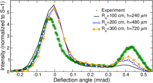
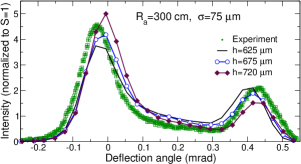
Two panels in Fig. 4 correspond to two sets of and . In each panel, the simulations have been performed for different values of the beam center at the entrance. Vertical lines in Fig. S1 in SM allow one to compare the values indicated with the boundaries and .
The left panel presents a case study in which m is comparable to the beam size so that for any entrance point within a large fraction of the particles is not accepted resulting in a noticeable decrease of the right peak. The curve with m corresponds to the case when half of the beam enters the crystal having . In this domain the volume reflection can occur shifting the main maximum towards negative angles. As increases the numbers of both channeling and volume reflected particles decrease leading to the shift of the both maxima to the right as well as to the change in their heights. At m, which corresponds to , most of the beam particles do not comply with the channeling condition but experiencing multiple scattering as in amorphous medium. As a result the main peak becomes more powerful being centered at .
To increase the channeling fraction one can rely on a larger value of the anticlastic radius and on a narrower beam. For cm, Fig. 4 right, the quantities and are 600 and 240 m, respectively. The latter value together with the reduced beam size ( m) suggest that a much bigger fraction of the particles can be accepted provided the condition is met. The best agreement with the experiment has been found for m (open circles). This dependence is shown in Fig. 2 in the form of a histogram.
The quantitative analysis of the angular distribution of ultrarelativistic electrons deflected by oriented qmBCs presented in our paper demonstrates the good agreement with experimental data reported in Wienands2015 . It has been achieved by accounting for (i) the specific geometry of such crystals and their orientation with respect to the projectile beam and (ii) the realistic beam size and divergence. Remaining discrepancies can be attributed to the uncertainty in concrete values of the beam characteristics and of the entrance coordinate of the beam center as well as to the effects not included into the current simulations (e.g., quantum effects in multiple scattering in crystals TikhomirovPRAB2019 ). It is highly desirable that such information is provided when presenting the experimental data since it allows for its independent unambiguous theoretical and computational validation. Important issue concerns also accurate measurement and computational analysis of the characteristics of radiation that accompany passage of ultra-relativistic projectiles through oriented crystals. Such knowledge is essential for better planning of accelerator-based experiments and for full interpretation of their results.
The work was supported in part by the DFG Grant (Project No. 413220201) and by the H2020 RISE-NLIGHT project (GA 872196). We acknowledge helpful discussions with Andrea Mazzolari, Vincenzo Guidi, Hartmut Backe and Werner Lauth. Frankfurt Center for Scientific Computing (CSC) is acknowledged for providing computer facilities.
References
- (1) A. V. Korol and A. V. Solov’yov, Crystal-based intensive gamma-ray light sources. Europ. Phys. J. D 74, 201 (2020).
- (2) A. V. Korol and A. V. Solov’yov, All-atom relativistic molecular dynamics simulations of channeling and radiation processes in oriented crystals. Europ. Phys. J. D 75, 207 (2021).
- (3) M. Krasny, The Gamma Factory proposal for CERN. CERN Proc. 1, 249 (2018).
- (4) http://www.mbnresearch.com/N-Light/main
- (5) TECHNO-CLS project (GA: 101046458) within the HORIZON-EIC Framework.
- (6) A. V. Korol, A. V. Solov’yov, and W. Greiner, Channeling and Radiation in Periodically Bent Crystals, Second ed., Springer-Verlag, Berlin, Heidelberg, 2014.
- (7) A. Mazzolari, E. Bagli, L. Bandiera, V. Guidi, H. Backe, W. Lauth, V. Tikhomirov, A. Berra, D. Lietti, M. Prest, E. Vallazza, and D. De Salvador, Steering of a sub-GeV electron beam through planar channeling enhanced by rechanneling. Phys. Rev. Lett. 112, 135503 (2014).
- (8) U. Wienands, T. W. Markiewicz, J. Nelson, R. J. Noble, J. L. Turner, U. I. Uggerhøj, T. N. Wistisen, E. Bagli, L. Bandiera, G. Germogli, V. Guidi, A. Mazzolari, R. Holtzapple, and M. Miller, Observation of deflection of a beam of multi-GeV electrons by a thin crystal. Phys. Rev. Lett. 114, 074801 (2015).
- (9) L. Bandiera, E. Bagli, G. Germogli, V. Guidi, A. Mazzolari, H. Backe, W. Lauth, A. Berra, D. Lietti, M. Prest, D. De Salvador, E. Vallazza, and V. Tikhomirov, Investigation of the electromagnetic radiation emitted by sub-GeV electrons in a bent crystal. Phys. Rev. Lett. 115, 025504 (2015).
- (10) L. Bandiera, E. Bagli, V. Guidi, A. Mazzolari, A. Berra, D. Lietti, M. Prest, E. Vallazza D. De Salvador, and V. Tikhomirov. Broad and Intense Radiation Accompanying Multiple Volume Reflection of Ultrarelativistic Electrons in a Bent Crystal. Phys. Rev. Lett. 111, 255502 (2013).
- (11) A. Mazzolari, M. Romagnoni1, R. Camattari, E. Bagli, L. Bandiera, G. Germogli, V. Guidi1, and G. Cavoto, Bent crystals for efficient beam steering of multi TeV-particle beams. Eur. Phys. J. C 78, 720 (2018).
- (12) A.I. Sytov, V. Guidi, V. V. Tikhomirov, E. Bagli, L. Bandiera, G. Germogli, and A. Mazzolari. Planar channeling and quasichanneling oscillations in a bent crystal. Eur. Phys. J. C 76, 77 (2016).
- (13) T. N. Wistisen, U. I. Uggerhøj, U. Wienands, T. W. Markiewicz, R. J. Noble, B. C. Benson, T. Smith, E. Bagli, L. Bandiera, G. Germogli, V. Guidi, A. Mazzolari, R. Holtzapple, and S. Tucker. Channeling, volume reflection, and volume capture study of electrons in a bent silicon crystal. Phys. Rev. Acc. Beams 19, 071001 (2016).
- (14) V. Guidi, A. Mazzolari, D. De Salvador, and A. Carnera, Silicon crystal for channelling of negatively charged particles, J. Phys. D: Appl. Phys. 42, 182005 (2009).
- (15) R. Camattari, V. Guidi, V. Bellucci, and A. Mazzolari. The quasi-mosaic effect in crystals and its application in modern physics. J. Appl. Cryst. 48, 977 (2015).
- (16) A. Mazzolari, M. Romagnoni, R. Camattari, E. Bagli, L. Bandiera, G. Germogli, V. Guidi, G. Cavoto. R. Camattari, V. Guidi, V. Bellucci, and A. Mazzolari. Bent crystals for efficient beam steering of multi TeV-particle beams. Eur. Phys. J. C 78, 720 (2018).
- (17) S. Lekhnitskii. Theory of Elasticity of an Anisotropic Body. Moscow: Mir Publishers, 1981.
- (18) O. I. Sumbaev. Reflection of Gamma-Rays From Bent Quartz Plates. JETP 5, 1042 (1957).
- (19) Y. Ivanov, A. Petrunin, and V. Skorobogatov. Observation of the elastic quasi-mosaicity effect in bent silicon single crystals. JETP Lett. 81, 977 (2005).
- (20) A. M. Taratin and S. A. Vorobiev, Volume trapping of protons in the channeling regime in a bent crystal. Phys. Lett. 115, 398 (1986).
- (21) A. M. Taratin and S. A. Vorobiev, Volume reflection of high-energy charged particles in quasi-channeling states in bent crystals. Phys. Lett. 119, 425 (1987).
- (22) Mauro Pivi and Carsten Hast. ESTB End Station Test Beam Design, Performance, Infrastructure, Status. ESTB 2012 Users Meeting, SLAC (August 23, 2012).
- (23) H. Backe, P. Kunz, W. Lauth, and A. Rueda, Planar Channeling Experiments with Electrons at the 855-MeV Mainz Microtron. Nucl. Instrum. Methods B 266, 3835 (2008).
- (24) I. A. Solov’yov, A. V. Yakubovich, P. V. Nikolaev, I. Volkovets, and A. V. Solov’yov, MesoBioNano Explorer – A universal program for multiscale computer simulations of complex molecular structure and dynamics.. J. Comp. Phys. 33, 2412 (2012).
- (25) G. B. Sushko, V. G. Bezchastnov, I. A. Solov’yov, A. V. Korol, W. Greiner, and A. V. Solov’yov, Simulation of ultra-relativistic electrons and positrons channeling in crystals with MBN Explorer. J. Comp. Phys. 252, 404 (2013).
- (26) I. A. Solov’yov, A. V. Korol, and A. V. Solov’yov, Multiscale Modeling of Complex Molecular Structure and Dynamics with MBN Explorer. Springer International Publishing, Cham, Switzerland (2017).
- (27) G. B. Sushko, I. A. Solov’yov, and A. V. Solov’yov, Modeling MesoBioNano systems with MBN Studio made easy. J. Mol. Graph. Model. 88, 247 (2019).
- (28) E. Bagli and V. Guidi, DYNECHARM++: a toolkit to simulate coherent interactions of high-energy charged particles in complex structures. Nucl. Instrum. Methods B 309, 124 (2013).
- (29) V.V. Tikhomirov: Quantum features of high energy particle incoherent scattering in crystals. Phys. Rev. Accel. Beams 22, 054501 (2019) (Erratum: Phys. Rev. Accel. Beams 23, 039901 (2020)).