Collective plasma effects of electron-positron pairs in beam-driven QED cascades
Abstract
Understanding the interplay of strong-field QED and collective plasma effects is important for explaining extreme astrophysical environments like magnetars. It has been shown that QED pair plasmas is possible to be produced and observed by passing a relativistic electron beam through an intense laser field. This paper presents in detail multiple sets of 3D QED-PIC simulations to show the creation of pair plasmas in the QED cascade. The beam driven method enables a high pair particle density and also a low particle gamma factor, which both play equal rolls on exhibiting large collective plasma effects. Finite laser frequency upshift is observed with both ideal parameters ( laser laser colliding with electron beam) and with existing technologies ( laser laser colliding with electron beam).
I Introduction
The QED plasma regime is an emerging topic which studies the interplay between the strong-field quantum and collective plasma effects when the Schwinger field is greatly exceeded. This regime dictates the dynamics of intriguing astrophysical environments like magnetars [1, 2], binary neutron-star mergers [3, 4], and core-collapse supernovae explosions [5, 6]. Understanding the plasma physics of these extreme environments [7, 8, 9], including for the emerging field of multi-messenger astronomy [10, 11, 12, 13, 14], is critical. For example, magnetars [15, 16, 17, 18, 19] are filled with strong-field QED cascades of relativistic electron-positron pair plasma [20, 21, 22, 23] in their magnetospheres. The relativistic particle emission in the varying magnetic field of magnetars is very likely responsible for the Fast Radio Bursts [24, 25, 26, 27].
Tremendous effects have been made to understand the QED plasma dynamics [28, 29, 30, 31, 32, 33, 34, 35, 36, 37, 38, 39, 40, 41, 42, 43, 44, 45, 46, 47] and to explore possibilities of their preparation in laboratories [48, 49, 50, 51, 52, 53, 54, 55, 56, 57, 58, 59, 60]. The QED plasma dynamics [61, 9, 60, 62] is characterized by strong field QED and collective plasma effects. The QED nonlinearity is observed only in fields above the QED critical limit , often called Schwinger limit [63]. In such a strong field, high energy photons and electron-positron pairs are created in a cascaded manner [64, 65, 66, 67, 68, 69, 70, 71, 72, 73, 74, 75]. The required particle density to manifest collective plasma effect depends on the observation method. Emission in the infrared wavelength (to which the detectors are most sensitive) corresponds to a particle density of near . For a volume, the total charge of pair plasma needs to reach .
In a recent publication [60], we demonstrated the generation of a quasi-neutral pair-plasma with a density that is comparable to the critical one by using the combination of a laser and a dense electron beam or by using less stringent parameters. This method circumvents the technological limitations by taking advantage of the high quality energetic electron beam facilities to boost the laser intensity in the particle rest frame.
I.1 e--beam-driven cascade v.s. all-optical method
We need to work in the rest frame of high energy particle beams, because reaching the Schwinger field limit directly in laboratories is still beyond the extend of current technology. A multi-GeV electron beam from a particle accelerator have a gamma factor of over , which can boost the laser fields by the same number. The seminal SLAC E-144 experiment [76, 77] has already used this method to observe evidences of nonlinear Compton scattering and Breit-Wheeler pair production by colliding a laser and a electron beam. Due to relatively low laser intensity, only a limited number of positrons were produced to exhibit any collective plasma effects. The upcoming experiment SLAC FACET-II will deploy a new laser with over peak intensity. Combined with the LCLS-Cu LINAC [78, 79, 80], pair multiplication factor over unity can be achieved providing a unique opportunity to explore nonperturbative QED cascade.
The counterpart of beam-driven QED cascade is by using two colliding ultra-strong lasers. The strong beat accelerates the seed electrons to the relativistic speed, which in turn boosts the laser field amplitude. As soon as the QED critical field is reached in the electron rest frame, high energy photons are emitted and pairs are created. The strong laser continues to accelerate the particles to induce a QED cascade. With sufficiently strong laser field, QED cascade is manifested in the rest frame of the pair particles and the created pair plasmas. It was proposed [48] that laser intensities above is sufficient to probe the QED critical field in the particle rest frame. This all-optical method has prompted investigation both analytically and numerically [48, 49, 50, 51, 52, 53, 54, 55, 56, 57, 58, 59]. However, the laser intensity required by the all-optical method needs a highly non-trivial tight focus of a laser [81, 82, 83]. Solving this challenge will depend on substantial development beyond current state-of-the-art laser technology. Even if the pair plasma is created, the pair particles have a large gamma factor of which greatly suppresses the plasma frequency observed in the laboratory frame.
Compared with the all-optical method, the beam-driven approach lowers the laser intensity requirement by two orders of magnitudes. This is owing to that the particle accelerators can produce multi-GeV or even tens of GeV electron beam energy, corresponding to gamma factors of . A PW-level laser can already induce QED pair multiplication. Such laser systems are routinely operated in several laboratories [84]. The all-optical method only accelerates the electrons to a gamma factor similar to the laser dimensionless amplitude ; Even reaching needs laser intensity of over [48, 49, 50, 51, 52, 53, 54, 55, 56, 57, 58, 59] and thus requires large -scale laser facilities [81, 82, 83].
I.2 Producibility v.s. observability of the pair plasmas
As the pair density grows in a QED cascade, they begin to behave collectively as a plasma. Existing experimental detectors like magnetic spectrometer can only distinguish electron and positron particles but cannot measure the pair density or test collective plasma effect. The figure of merit for collective plasma dynamics is determined by the plasma frequency () which is proportional to the ratio of pair particle density () and pair gamma factor (), i.e., . The inverse proportionality to the pair gamma factor favors the beam-driven approach over the all-optical approach. Since the average pair gamma factor is similar to the laser dimensionless amplitude, the lower laser intensity needed for the beam-driven approach greatly reduces the average gamma factor of the produced pair plasma. It thus exhibits higher plasma frequency even if the colliding lasers can produce the same plasma density. The counter propagating laser pulse and pairs also provide possibilities to further slow down the pairs through laser radiation pressure. Thus, the pair plasma created in a beam-driven QED cascade is easier to detect than one created with the all-optical approach.
The laser which is used to create the pair plasma also informs the pair plasma frequency through its change of spectrum. Both as the pair plasma forms and as it slows down, the plasma frequency increases inside the laser field. The increase of plasma frequency abruptly reduces the vacuum refractive index which the laser is mediated. The consequence is that the laser frequency is upshifted and laser wavelength is blue shifted, according to the theory of temporal change of optical refractive index [85, 86, 87, 88, 89, 90, 91, 92, 93, 94]. The pair oscillation, which is responsible for the laser frequency upshift, is coupled to the intense laser field to radiate a strong signal. Thus, remarkably, despite the small plasma volume and despite the relativistic plasma motion, signatures of the QED plasma regime might be identified experimentally with state-of-the-art technology. On the contrary, the small plasma volume (m-scale) eliminates the possibility of using conventional detection methods, e.g., by observing plasma instabilities like the two-stream instability [95], the Weibel instability [96], or stimulated Brillouin scattering (SBS) [97].
This paper is organized in the following structure: In Sec. II, we briefly review the process of QED cascade in an electron-beam-laser collision. This offers the background for explaining our numerical simulation results. In Sec. III, we introduce the setup of our 3D PIC QED simulations and show the production of electron-positron pairs. In Sec. IV, we focus on the pair deceleration through both synchrotron emission and through laser radiation pressure. The important pair reflection condition is introduced here. In Sec. V, we analyze the laser dynamics and show how its spectrum changes with the increasing plasma frequency. Multiple optical detection methods are explained including laser central frequency shift, chirping, and homodyne detection of the laser phases. In Sec. VI, we verify the scaling of the laser frequency shift with different electron beam and laser parameters. In Sec. VII, we demonstrate the possibility of creating and observe a QED plasma using state-of-the-art parameters, i.e., a laser and a electron beam. In Sec. VIII, we present our conclusions.
II Pair generation through beam-driven QED cascade
We first provide a brief overview of the QED cascade process. In an electron-beam-driven QED cascade, an energetic electron beam collides with a counter-propagating strong laser field. The laser amplitude is greatly boosted to exceed the critical field in the electron rest frame. Thus, the electrons emit photons which further split into electron-positron pairs. Each of the pair particles, given sufficient energy, can continue the photon emission and pair generation process to induce a cascaded generation of pairs. The process converts high electron beam energy into large pair numbers. In this section, we layout the properties of beam-driven QED cascade while we briefly explain how the electron-positron pairs are generated.
In the initial stage of the collision, the electron beam has the maximum energy with a Lorentz factor . It boosts the counter-propagating laser field by the same factor in the rest frame of the electrons. Such a boost aims to produce a large quantum parameter , where and are the electric and magnetic field of the laser in the laboratory frame, and is the electron beam speed normalized to the speed of light . The strong laser field drives the electron motion, causing emission of photons [64, 98].
The photon emission spectra differ depending on the quantum parameter . The regime is reached near the laser intensity peaks where quantum synchrotron emission causes the electrons to emit almost all of its energy into a single gamma ray. In the regions of low laser intensity , the emission is classical. The emitted photon only takes a small portion of the electron energy , i.e., . These low energy photons would escape the laser focus spot without decaying into pairs.
The high-energy gamma ray photons are highly likely to decay into an electron-positron pair in the same strong laser field. For the interest of this paper, we focus on the Breit-Wheeler process that a photon decays into one pair of electron and positron. The decaying process also depends on the quantum parameter of the emitted photon with () being the photon energy (momentum), and being the electron rest mass. The pair generation happens only when is above the unit threshold value. For , the photon transfers almost all of its energy to either the electron or positron, whiles for smaller values the photon energy is more symmetrically partitioned.
Therefore, a very intense laser can cause a cascade of gamma rays and pairs from a single energetic electron. Each subsequent emission and decay process transfers the energy into predominantly to one new particle and creates many other particles with lower energies. The gamma photon decay process first terminates when though the high-energy pairs continue to emit photons until . For an electron beam with original gamma factor and density and a laser with dimensionless amplitude and frequency , the pair multiplication rate is approximately
| (1) |
This relation holds only if the laser pulse is sufficiently wide and long. The multiplication rate for finite laser pulse waist and duration could cause deviation from the estimation of multiplication, but the linear scaling should nevertheless hold in general.
The plasma frequency is dependent on the ratio of particle density and mass . Hence, the collective effects, if they were to be probed, are manifested through the oscillation of the low energy particles in the strong laser field. Since the pair formation rate is inversely proportional to the laser amplitude , the pairs are more likely to be created when the laser is strong, which thereby drives the strongest collective pair oscillation.
III 3D PIC QED simulations of pair creation
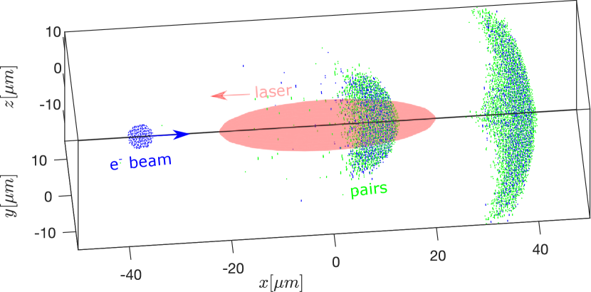
To set up the electron-beam and laser collision for QED cascade, the above analysis shows that it requires including an intense laser field with and an electron beam with high factor such that . Towards this limit, we consider head-on collision of a nC electron beam of GeV [99, 100], shown as a blue sphere in Fig. 1, and a PW laser pulse [82] with wavelength , shown as an yellow spheroid. The corresponding dimensionless laser amplitude is and the quantum parameter is at the Gaussian waist in the focal plane, and at the laser focus.
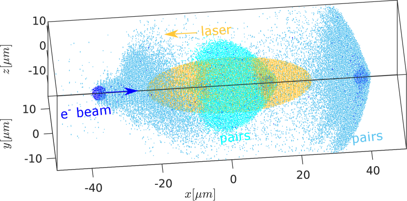
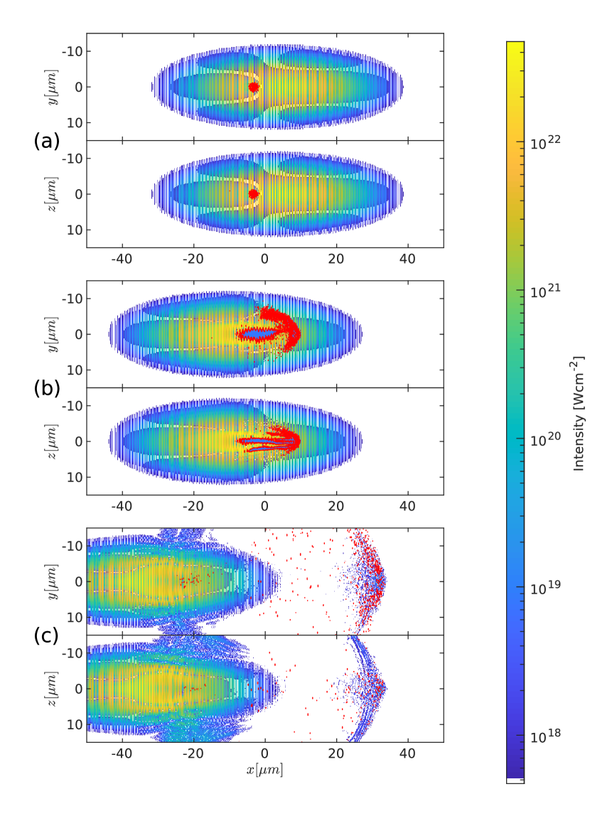
The electron beam has a spherical Gaussian number density , where is the peak density and m is the rms radius of the sphere. The counter-propagating laser pulse is linearly polarized in the direction and propagates in the direction. It has a Gaussian distribution in both transverse and longitudinal directions with where is the peak intensity, m is the waist at , , is the Rayleigh length, and is the pulse duration (intensity FWHM: , electrical field FWHM: ). Each dot in Fig. 1(a) represents a region with pair density above or laser intensity above .
The simulations were performed using the PIC code EPOCH [101, 102] with the QED module [59, 73, 53]. The simulation box measured is discretized into cells. The charged particles are represented by near computing particles. The time step is determined by the Courant–Friedrichs–Lewy condition and the inverse plasma frequency, i.e., it is chosen as the smaller value of the minimum plasma oscillation period in any cells and the smallest cell dimension multiplied by . The actual time step in our simulations is , which is well below the maximum possible photon emission time [102] fs in all our simulations.
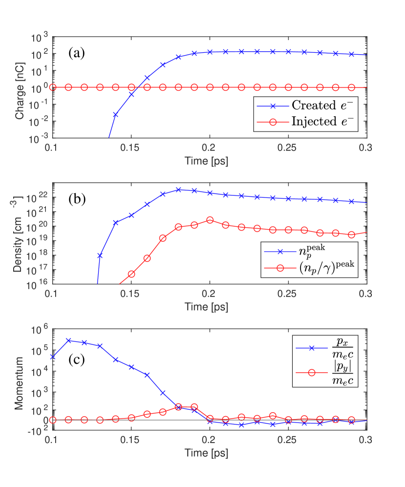
With the large quantum parameter , the collision quickly creates a pair plasma with an increasing charge number. Figure 2(a) shows the evolution of total charge of the injected electrons (blue) and created electrons (red). The injected electron remains throughout the interaction. Pair electrons charge first grows exponentially until it reaches the total charge at and remains unchanged afterwards.
The peak density of the created pairs, shown as the blue curve in Fig.2(b), quickly grows to a peak value of , but begins to slowly decrease at . The decrease of peak density is caused by plasma volume expansion, illustrated at three different stages in Fig. 1a. Since the pair particles are mostly created in the region of strong laser field, the pair particles immediate accelerate transversely causing volume expansion. The transverse motion also allows the particle to escape the high intensity laser focus resulting in a lower total charge than predicted by Eq. (1).
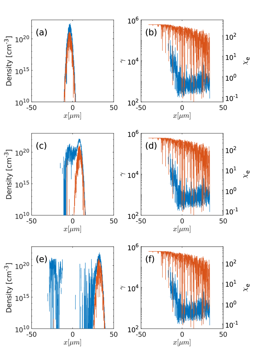
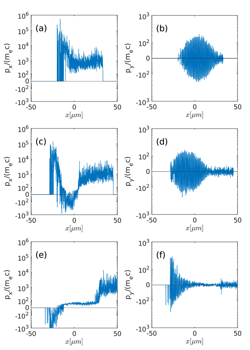
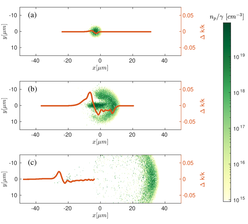
To get more insight of the dynamics of pair generation, we analyze the the pair density and momentum at the center line with peak laser intensity, shown in Fig. 3 and Fig. 4. The top row of these two figures show the snapshot at . At this time, the center of the electron sphere has not reached the laser focal plane though a significant amount of pairs have been generated. The density plot in Fig. 3(a) shows that the generated pairs are limited to the region near the electron beam. The gamma factor plot in Fig. 3(b) shows that the electron beam energy is decreased by orders of magnitude from its initial value after passing through the laser peak. The generated pairs have an energy of near , corresponding a quantum parameter of , after passing through the laser peak. This is the lowest particle energy that can be efficiently generated via the photon decay process. Beyond this point, the gamma photons can no longer decay into pairs and the QED cascade terminates, which can be seen from the saturation of charge growth in Fig. 2(a). However, the pairs continue to lose energy, which we will explain in detail in the following section.
IV Pair deceleration and pair reflection
We observed and explained in the previous section that the injected electron beam would emit high energy photons which decay into pair particles in a strong laser field until the photon energy (and hence the generated pair energy) decreases to when the QED cascade terminates. The pairs, however, continue to lose energy via synchrotron radiation, as shown in Fig. 2(c).
The photon emission is dominated by quantum synchrotron radiation when . The decrease of pair energy can be seen in Fig. 3(d) and (f), which shows the snapshot immediately after the center of the electron sphere passes through the laser peak. The blue curve in Fig. 3(d) shows that the generated pair energy further decreases to , corresponding to , at the tail of the electron beam. Depending on the laser amplitude , quantum synchrotron emission can reduce the pair gamma factor to
| (2) |
Figure 3(c) shows that these low-energy pairs are created through the secondary generation from the daughter pairs, and thereby they tailgate the injected electron beam.
Quantum synchrotron emission stops when reaches , and classical radiation emission begins to dominate [64]. The pair particles wiggle in the laser field to radiate electromagnetically with negligible quantum contributions like recoil or spin. The strong laser field drives transverse motion of the pairs, evidenced in Fig 4(b,d) for that the transverse pair momentum is enveloped by the laser profile and that locally. Due to the conservation of canonical momentum, each charged particle transfer the amount of longitudinal momentum to a counter-propagating laser field upon entering it. It means that particles can be stopped or even reflected by the strong laser field if they have sufficiently low longitudinal momentum, i.e., , or equivalently, [103]. By comparing this condition with Eq.(2), we find that particle reflection is possible if
| (3) |
for a sufficiently long laser pulse. For optical lasers with , the threshold is approximately , corresponding to intensity . Particle reflection is shown in Fig. 2(c) and Fig. 4(c) and (e) as the pair longitudinal momentum becomes negative near the laser peak. The reflected pair can also be observed in Fig. 1(c) as the spreading pairs (light blue dots) throughout the simulation box at ps.
The particle reflection threshold is very important in probing the collective pair effects because the pair particle mass reaches their minimum value as they stop longitudinally. Since plasma dynamics is manifested through plasma frequency which is proportional to , achieving lower particle energy is equally important with higher particle density. Thus, we plot the parameter in Fig. 2(b). The red curve shows that the parameter continues to increase even after the pair density reaches its peak value at . The pair momentum and decreases to its minimum value at when reaches its peak value of at . Thus, the beneficial synchrotron radiation, which keeps reducing the pair energy, outweighs the density increase between and until finally the latter effect dominates.
While the strong laser field causes the pairs to lose longitudinal momentum , it at the same time increases the transverse momentum . The maximum value of is identical to local laser amplitude due to conservation of canonical momentum. Therefore, the minimum pair gamma factor is equal to the laser amplitude provided that the particle reflection threshold condition Eq. (3) is satisfied. This is evident in Fig. 3(d) and (f) which shows a minimum gamma factor of . Note that the particle reflection may happen behind the laser peak if we consider the finite time of particle deceleration by synchrotron radiation.
Thus, we provide the following “rule of thumb” for the maximum achievable pair plasma density and the relevant gamma factor
| (4) |
These relations are valid if the laser is above the threshold intensity for particle reflection [Eq.(3)], and if the interaction time is long enough such that the cascade reaches its asymptotic state.
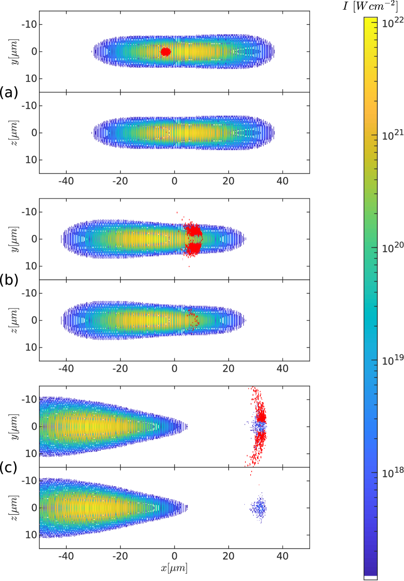
To illustrate the creation of pairs more clearly, we plot the profiles of pair density and laser intensity in the plane and plane as the top and bottom panels of Fig. 5, respectively. Each red dot denotes a region with at the corresponding plane. It is seen in Fig. 5(a) that the pairs are initially created nearby the injected electron beam. The pairs then expands to mainly the transverse directions shortly after the creation. Linear laser polarization breaks the cylindrical symmetry of pair motion. The -polarized laser naturally accelerates the pairs more strongly in the direction than in the direction, which is seen in Fig. 5(b). The asymmetry of pair expansion increases as shown in Fig. 5(c). Figure 5(c) also reveals rich dynamics of the laser profile, which will be discussed in detail in the following section.
V Laser beam diffraction and frequency upconversion
Since the pair generation rate is proportional to the laser amplitude, the pairs are dominantly created near the peak laser field. The strong laser field thus drives pairs into oscillation immediately after they are generated. Transverse current is induced from the pair oscillation which radiates electromagnetic fields. With non-negligible pair density, the radiation could reach a detectable level to reveal the pair dynamics. When the pair density reaches near the critical density, the radiation becomes strongly coupled to the input laser, causing a quantitative upshift of the laser frequency. Measuring the change of laser frequency allows us to unambiguously probe the collective pair plasma effects.
For a given input laser, the amount of laser blue shift reveals the plasma frequency of the pairs. Macroscopically, laser frequency upshift arises from non-adiabatic change of index of refraction, which determines the phase velocity of light. Suddenly created pairs reduces the index of refraction thereby increasing the laser phase velocity. It corresponds to increased local laser wave oscillation in the region of pairs and hence upshift of laser frequency.
Microscopically, the laser frequency upshift can be analyzed through finding the transverse current of the pair particles. As the pairs are almost always generated when strong laser field is present, they are immediately driven into an oscillatory motion. Assuming the pair particles have no transverse momentum at the time of generation. The laser field with vector potential can transfer transverse momentum of to the pairs. Thus, the pair transverse current is . Here, we define the plasma frequency . The factor of two accounts for the equal contribution of positrons and electrons to the laser dispersion relation. The transverse current couples to the laser field through the wave equation
| (5) |
from which we see that a non-adiabatic change of plasma frequency induces a change of laser frequency . If the plasma frequency is small compared with the input laser frequency , the laser frequency is approximated as
| (6) |
If the plasma is created non-instantly, the change of laser frequency needs to take an integral over the plasma frequency change at the retarded position :
| (7) |
The laser wave vector changes correspondingly obeying the dispersion relation
| (8) |
Equations (7) and (8) demonstrate that the change of laser frequency and wave vector is determined by the total temporal and spatial change of plasma density, respectively. In the limit of instantaneous plasma creation, the upshift of frequency and wave vector after interaction reduce to a simple form and . The relation of the instantaneous laser frequency and wave vector becomes very useful for interpreting our numerical simulation results: whereas experiments measure the laser frequency at a specific location, numerical simulations often more conveniently output the laser wave vector at a specific time. Equations. (7) and (8) provides a definite relation to transform the laser wave vector upshift into frequency upshift during the QED cascade.
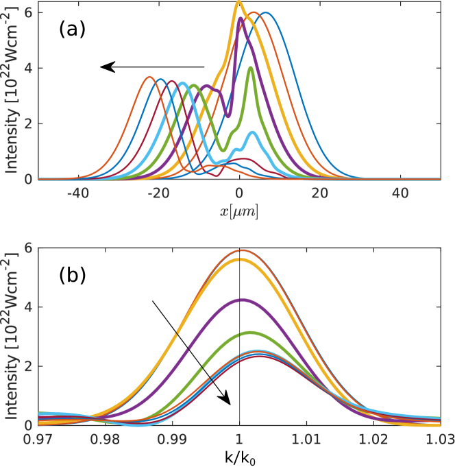
For the simulation under consideration, the peak value of corresponds to of the critical plasma density at rest of the drive laser. Accordingly, a laser frequency upshift is observed in the intensity spectra displayed in Fig. 6. Figure 6(a) shows the laser intensity in its propagation axis with each curve corresponding to from to , respectively, in the direction of the arrow. Figure 6(b) shows the corresponding intensity spectra by Fourier transformation. The peaks of the spectra before and after the collision reveals a wave vector upshift . Since the pair plasma counter propagates with the laser pulse, the laser wave vector spectrum becomes equivalent to the frequency spectrum after the collision: is also the laser frequency upshift. This finite frequency upshift is caused by the small fraction of laser overlap with the electron beam. Specifically, the frequency-upconverted photons are confined to a small region, whereas the majority of laser photons are not upconverted.
The oscillation motion of the high density pairs absorbs a significant amount of laser energy. It causes a decrease of laser peak intensity, which can be observed in Fig. 6. We highlight this process between and as thick curves in Fig. 6(a). This period corresponds to when the pair parameter approaches its peak value, as can be seen from Fig. 2(b). Actually, the pairs, after absorbing the laser energy, radiate to the whole space. It is reflected in Fig. 6(a) as splitting of the laser peak when the pairs are generated and laser frequency is upshifted. While the main laser peak continues to propagate to the direction, a second peak is developed at (thick purple curve) and propagates towards the direction.
Due to the small volume of the pairs, they emit a point-source-like radiation, as shown in Fig. 6(c). The large radiation angle can actually be used advantageous for experimental detection: It can be captured by an optical detector installed separated from the path of laser beam. The radiation is near the laser frequency and is hence easily distinguished from the high energy gamma photons.
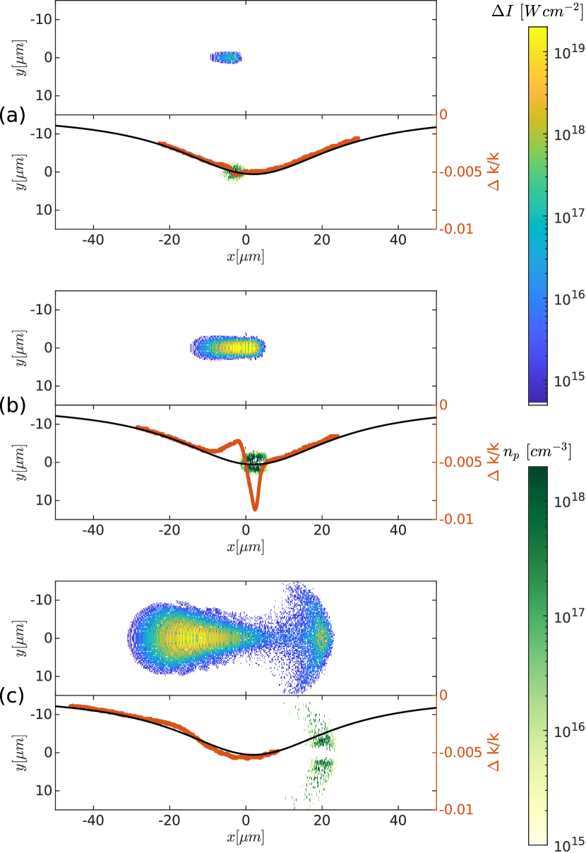
Much higher laser frequency upshift can be obtained when focusing on the region where pairs are quickly created. Such a laser spectrogram is typically obtained in experiments using techniques like frequency-resolved optical gating [104] or spectral shear interferometry for direct electric field reconstruction [105]. Numerically, we conduct a wavelet transform of the laser pulse and obtain precisely the laser photon wave vectors at different pulse positions plotted as red curves in Fig. 7. We also plot the pair particle density in the plane to demonstrate the correlation of pair plasma creation and laser wave vector upshift. Figure 7(a) shows that the wave vector spectrum becomes chirped immediately at the region of plasma creation near . The wave vector chirps up in the front of the interaction region and chirps down in the tail, which agrees with Eq. (8). As the pair density increases and the interaction continues, the amplitude of chirp grows, as seen in Fig. 7(b). The chirped region propagates along the laser direction [Fig. 7(c)] and gets separated with the pair plasma. Thus, it can eventually be collected by a detector and reveals as a chirped frequency spectrum. The maximum photon frequency shift reaches .

The small disturbance in laser phase and intensity can be precisely measured with an interferometer. As shown in Fig. 8, the strong laser is first sent through a beam splitter with a large reflection ratio. A small fraction of the laser pulse is split to serve as a reference beam, whose electric field can be denoted as The strong laser pulse, after interacting with the electron beam, becomes . Here, represents the accumulated local phase change and denotes the new envelope. The pulse is then attenuated to the same amplitude with the reference beam before they are combined through another beam splitter. The interference signal, called a homodyne signal, is
| (9) |
where the negative sign arises from the double reflection of the PW laser and the signal is averaged through an optical cycle to model the slow response time of the photo detector. The homodyne signal is sensitive to both the laser phase fluctuation and change of envelope. For only a small phase fluctuation , the homodyne signal is
| (10) |
where is the intensity of the reference beam. Since , one can find out the frequency shift through . Note that the proportional relation in Eq. (10) only holds for .
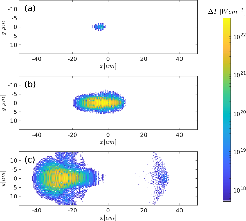
Numerically, we show the homodyne signal at three different snapshot in Fig. 9. The reference beam is obtain via a separate simulation of the same laser beam without encountering the electron beam. The interference signifies the change of electromagnetic field. It confirms that the radiation starts at the location where pairs are generated and then expands to the whole space. The radiation pattern in Fig. 9(c) consists of two types of signals, including a pattern that propagates a long the laser direction and a pattern that radiates to the whole space. The propagation radiation pattern is the result of interference of phase-shifted post-interaction beam and the reference beam. The latter radiation pattern is the point-source-like pair emission.
Our simulation assumes linearly polarized laser with an electric field in the -direction. Compared to a circularly polarized laser, the linear polarization can achieve -fold higher peak field amplitude at the same laser energy. Although the circularly polarized laser has a constant amplitude, the exponential dependence of the pair growth rate obviously favors higher amplitude of linear polarization.
VI Scaling of the laser frequency upshfit
Since upconversion of laser frequency is determined by the pair plasma frequency, it provides an unambiguous signature of collective plasma effects in beam-driven QED cascades. In the previous section, our 3D PIC simulations demonstrate the collective pair plasma effects during pair creation and energy decay, and show how the plasma signature is imprinted in the colliding laser. For the best results of illustration, the collision uses a laser pulse and a electron beam at . But can existing technology produce sufficiently high density pair plasma to exhibit observable collective effects? In this section, we answer the question by finding how the amount of frequency upshift scales with different parameters of the laser and electron beam.
It is made clear in Eqs. (5) and (6) that the magnitude of pair plasma radiation is determined by the pair plasma parameter , i.e., plasma density divided by pair energy. The spatial profile of the radiation depends on the pair size at the time of pair creation. High pair density is achieved through high input electron beam density and large pair multiplication rate , which, according to Eq. (1), is proportional to the laser amplitude , laser frequency , and electron beam energy .
For exhibiting collective effects, an equally important parameter is the pair energy or gamma factor. In a QED cascade, the pair energy decreases as a result of radiation recoil and ponderomotive potential of the laser field, as we explained in Sec. IV. The minimum pair energy is reached when the laser intensity meets the threshold for pair reflection, as shown in Eq. (3). Then, the pair motion becomes purely transverse and the pair gamma factor is , as shown in Eq. (4). By combining Eq.(6) with Eq.(4), we find
| (11) |
for the frequency upshift. This relation holds if the laser pulse is sufficiently long and intense such that the QED cascade fully develops and the pair plasma is eventually stopped and reflected.
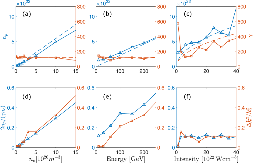
To verify Eq.(11), we conduct a series of 1D QED-PIC simulations with different electron beam densities, beam energies, and laser intensities. The 1D simulations discretize m-long box into cells. Both the envelopes of the electron beam density and the laser intensity have the same Gaussian shape as in the 3D simulations at . The laser pulse parameters are (corresponding to and ), m, and fs. The 1D simulations neglect transverse effects such as plasma inhomogeneity and laser diffraction, but keep three dimensional particle momenta and currents, which are critical for inducing the laser frequency upshift.
The results are shown in Fig. 10. The panels (a-b) consider electron beams with varying peak densities and energies colliding with a laser pulse with peak amplitude (), respectively. As , either increasing beam density or beam energy causes a linear increase of the created pair plasma density, whereas the final gamma factor remains constant at about . The results are in agreement with Eq.(4). The maximum frequency upshift shown in Fig. 10(d), and 10(e) obtained from the wavelet transform also shows decent agreement with Eq. (11).
Figures. 10(c) and 10(f) scan the laser intensity from () to (). For fixed electron beam energy the quantum parameter changes as . Therefore, we expect the final plasma density to show a similar scaling. Figure 10(f) clearly demonstrates the threshold dependence of the frequency upshift on the laser intensity. When the laser intensity is below , the pair reflection condition [Eq.(3)] is not satisfied and the cascade does not saturate within the pulse duration, causing minimum laser frequency upshift. But above the threshold amplitude, the quantity becomes independent of the laser intensity and the laser frequency upshift reaches its maximum value.
VII Collision of 3 PW laser and 30 GeV electron beam
In the previous sections, we presented a clear numerical demonstration that the interplay between collective plasma and strong-field quantum effects leaves a characteristic imprint on the driving laser pulse. The upshift of the instantaneous laser frequency, according to the “rule of thumb” [Eq.(11)], becomes experimentally observable by combining a multi-GeV class electron beam with density above and a laser at intensity. In principle, such beam-driven QED cascades could be initiated with electron beams obtained from either a linear accelerator or laser wakefield acceleration (LWFA) at all-optical laser facilities. But linear accelerators benefit from its much higher total charge number at nC-level compared with pC-level obtained from reported LWFA accelerated electrons [106]. The required electron beam density and beam energy can be obtained with only a moderate upgrade of existing facilities, e.g., SLAC’s FACET-II [107].

We conduct such 3D QED-PIC simulations to show the prospect. Figure 11 illustrates the simulation of a fs-duration, m-waist, PW () laser pulse colliding with a , , electron beam. Other numerical parameters are identical to the last 3D simulations. The generated pair plasma and the radiation are shown in Figs. 12 and 13. Figure 12(a) and (b) show that the created electron-positron pair plasma reaches a total charge number of and peak density of . The red dots in Fig. 13 show that the tightly focused laser punches a hole in the pair plasma and pushes the pairs away from the propagation axis. The created pairs begin to escape the simulation box from causing a decrease of total charge number as seen in Fig. 12(a).
With a lower energy, the injected electron beam has a much lower relativistic mass. The electrons are thus expelled by the strong laser ponderomotive force and expand with the created pair plasma. This is seen in Fig. 11 shows in which the blue dots mostly overlap with the green shades whereas the blue dots remain a sphere shape in Fig. 1. The expanding electron beam begin to leave the simulation window, causing a decreasing total charge from as seen in Fig. 12(a).
Since the laser intensity meets the threshold value for particle reflection, some pairs reverse their propagation direction. This is confirmed in Fig. 12(c) as the pair longitudinal momentum is about to change sign. The parameter reaches , corresponding to of the critical density of a laser.
We obtain the instantaneous wave vectors through a wavelet transform of the laser electric field at and plot them as red curves in Fig. 14. For comparison, we also plot the wave vectors of the same laser without encountering an electron beam as black curves. Due to the tight focus, the laser has a short Rayleigh length and the Gouy phase induces a down chirp of the wave vectors near the focal point. The red curves clearly show a laser wave vector upshift in the region of pair plasma creation. The maximum wave vector upshift reaches a value of .
In the top panels of Fig. 14, we plot the homodyne signal . Strong signals exhibit in the regions of pair plasma creation. The plots show that the interference signal immediately appears when the pairs are initially created. As the pair density grows, the signal reaches a maximum intensity of ,which can be easily detected in an experiment. At , the homodyne signal intensity increases by within a single laser period indicating a laser wave vector upshift.
VIII Conclusion and Discussion
In conclusion, we present QED PIC simulations for creating observable high-density electron-positron pair plasmas through strong-field QED cascades using existing laser and electron beam technologies. Analysis and numerical simulation demonstrate that both high pair density and low pair gamma factor are equally important for exhibiting strong collective plasma effects. A large pair plasma frequency can be achieved with dense and high-energy electron beam. A higher laser intensity can effectively increase the pair plasma frequency only below the threshold amplitude (). Laser intensities above the threshold re-accelerate the pairs in the counter-propagating direction, causing a higher pair gamma factor and thus a lower plasma frequency.
We specifically considered two sets of 3D PIC simulations, including one set with ideal parameters and the other set with existing technologies. The ideal parameter set uses a laser with a waist of , duration of , and peak intensity of (corresponding to ). Combined with a , , peak density electron beam, it creates a plasma with peak density of , which is times higher than the injected electron beam. The pair parameter reaches a peak value of , which is of the critical density of the laser. The simulation shows a laser frequency upshift of at the output and a maximum wave vector upshift of during the collision.
We further demonstrate that the collective QED plasma signature can be observed with state-of-the-art technologies. Even a electron beam and a -waist laser (other parameters are identity to the previous 3D PIC simulation) can create a pair plasma of and induce a laser frequency upshift. It suggests how hitherto unobserved collective effects can be probed with existing state-of-the-art laser and beam technologies, suggesting a strong argument for colocating these technologies.
Our results demonstrate that the co-location [108, 109] of a dense, electron beam with a optical laser enables us to reach the QED plasma regime at substantially lower laser intensities (). Whereas it has been well known that QED cascades can be studied in electron-beam laser collisions[65], our results recognize the importance of the electron beam density, showing that the beam-compression techniques developed in the context of FACET-II are indeed sufficient to probe the interplay between collective plasma and strong-field quantum effects with a laser-electron-beam setup. In fact, compared to all-optical methods of reaching the QED regime, the use of lower laser intensities reduces the particle mass shift, thereby remarkably makes the QED collective effects easier to observe.
The beam-laser collision setup, together with the proposed observable, opens seminal possibilities for studying laboratory astrophysics and High Energy Density Physics (HEDP) by providing access to the QED plasma regime with available technology.
Acknowledgements.
This work was supported by NNSA Grant No. DE-NA0002948, and AFOSR Grant No. FA9550-15-1-0391.References
- Kaspi and Beloborodov [2017] V. M. Kaspi and A. M. Beloborodov, “Magnetars,” Annu. Rev. Astron. Astrophys. 55, 261 (2017).
- Cerutti and Beloborodov [2017] B. Cerutti and A. M. Beloborodov, “Electrodynamics of Pulsar Magnetospheres,” Space Sci. Rev. 207, 111 (2017).
- Xue et al. [2019] Y. Q. Xue, X. C. Zheng, Y. Li, et al., “A magnetar-powered X-ray transient as the aftermath of a binary neutron-star merger,” Nature 568, 198 (2019).
- Price and Rosswog [2006] D. J. Price and S. Rosswog, “Producing Ultrastrong Magnetic Fields in Neutron Star Mergers,” Science 312, 719 (2006).
- Mösta et al. [2015] P. Mösta, C. D. Ott, D. Radice, L. F. Roberts, E. Schnetter, and R. Haas, “A large-scale dynamo and magnetoturbulence in rapidly rotating core-collapse supernovae,” Nature 528, 376 (2015).
- Akiyama et al. [2003] S. Akiyama, J. C. Wheeler, D. L. Meier, and I. Lichtenstadt, “The Magnetorotational Instability in Core-Collapse Supernova Explosions,” Astrophys. J 584, 954 (2003).
- Uzdensky and Rightley [2014] D. A. Uzdensky and S. Rightley, “Plasma physics of extreme astrophysical environments,” Rep. Prog. Phys 77, 036902 (2014).
- Uzdensky et al. [2019] D. Uzdensky, M. Begelman, A. Beloborodov, et al., “Extreme Plasma Astrophysics,” (2019), arXiv:1903.05328 .
- Zhang et al. [2020] P. Zhang, S. S. Bulanov, D. Seipt, A. V. Arefiev, and A. G. R. Thomas, “Relativistic plasma physics in supercritical fields,” Phys. Plasmas 27, 050601 (2020).
- Wang et al. [2020] M.-H. Wang, S.-K. Ai, Z.-X. Li, N. Xing, H. Gao, and B. Zhang, “Testing the Hypothesis of a Compact-binary-coalescence Origin of Fast Radio Bursts Using a Multimessenger Approach,” Astrophys. J 891, L39 (2020).
- Abbott et al. [2020] B. P. Abbott, R. Abbott, T. D. Abbott, et al., “GW190425: Observation of a Compact Binary Coalescence with Total Mass ,” Astrophys. J 892, L3 (2020).
- LIGO Scientific Collaboration and Virgo Collaboration [2017] LIGO Scientific Collaboration and Virgo Collaboration, “GW170817: Observation of Gravitational Waves from a Binary Neutron Star Inspiral,” Phys. Rev. Lett. 119, 161101 (2017).
- Palenzuela et al. [2013] C. Palenzuela, L. Lehner, M. Ponce, S. L. Liebling, M. Anderson, D. Neilsen, and P. Motl, “Electromagnetic and Gravitational Outputs from Binary-Neutron-Star Coalescence,” Phys. Rev. Lett. 111, 061105 (2013).
- Anderson et al. [2008] M. Anderson, E. W. Hirschmann, L. Lehner, S. L. Liebling, P. M. Motl, D. Neilsen, C. Palenzuela, and J. E. Tohline, “Magnetized Neutron-Star Mergers and Gravitational-Wave Signals,” Phys. Rev. Lett. 100, 191101 (2008).
- Lin et al. [2020] L. Lin, C. F. Zhang, P. Wang, et al., “No pulsed radio emission during a bursting phase of a Galactic magnetar,” Nature 587, 63 (2020).
- Ridnaia et al. [2021] A. Ridnaia, D. Svinkin, D. Frederiks, A. Bykov, S. Popov, R. Aptekar, S. Golenetskii, A. Lysenko, A. Tsvetkova, M. Ulanov, and T. L. Cline, “A peculiar hard x-ray counterpart of a galactic fast radio burst,” Nature Astronomy 5, 372 (2021).
- Li et al. [2021] C. K. Li, L. Lin, S. L. Xiong, et al., “HXMT identification of a non-thermal X-ray burst from SGR J1935+2154 and with FRB 200428,” Nature Astronomy 5, 378 (2021).
- Bochenek et al. [2020] C. D. Bochenek, V. Ravi, K. V. Belov, G. Hallinan, J. Kocz, S. R. Kulkarni, and D. L. McKenna, “A fast radio burst associated with a Galactic magnetar,” Nature 587, 59 (2020).
- Andersen et al. [2020] B. C. Andersen, K. M. Bandura, M. Bhardwaj, et al., “A bright millisecond-duration radio burst from a Galactic magnetar,” Nature 587, 54 (2020).
- Chen, Cruz, and Spitkovsky [2020] A. Y. Chen, F. Cruz, and A. Spitkovsky, “Filling the Magnetospheres of Weak Pulsars,” Astrophys. J 889, 69 (2020).
- Timokhin and Harding [2019] A. N. Timokhin and A. K. Harding, “On the Maximum Pair Multiplicity of Pulsar Cascades,” Astrophys. J 871, 12 (2019).
- Gueroult et al. [2019] R. Gueroult, Y. Shi, J.-M. Rax, and N. J. Fisch, “Determining the rotation direction in pulsars,” Nat. Commun. 10, 1 (2019).
- Melrose and Yuen [2016] D. B. Melrose and R. Yuen, “Pulsar electrodynamics: an unsolved problem,” J. Plasma Phys. 82, 635820202 (2016).
- Marcote et al. [2020] B. Marcote, K. Nimmo, J. W. T. Hessels, et al., “A repeating fast radio burst source localized to a nearby spiral galaxy,” Nature 577, 190 (2020).
- The CHIME/FRB Collaboration [2019] The CHIME/FRB Collaboration, “A second source of repeating fast radio bursts,” Nature 566, 235 (2019).
- Ravi et al. [2019] V. Ravi, M. Catha, L. D’Addario, S. G. Djorgovski, G. Hallinan, R. Hobbs, J. Kocz, S. R. Kulkarni, J. Shi, H. K. Vedantham, S. Weinreb, and D. P. Woody, “A fast radio burst localized to a massive galaxy,” Nature 572, 352 (2019).
- Bannister et al. [2019] K. W. Bannister, A. T. Deller, C. Phillips, et al., “A single fast radio burst localized to a massive galaxy at cosmological distance,” Science 365, 565 (2019).
- Óscar Amaro and Vranic [2021] Óscar Amaro and M. Vranic, “Optimal laser focusing for positron production in laser-electron scattering,” (2021), arXiv:2106.01877 [physics.plasm-ph] .
- Luo et al. [2018a] W. Luo, W.-Y. Liu, T. Yuan, M. Chen, J.-Y. Yu, F.-Y. Li, D. Del Sorbo, C. P. Ridgers, and Z.-M. Sheng, “QED cascade saturation in extreme high fields,” Scientific Reports 8, 8400 (2018a).
- Liu et al. [2018] J.-x. Liu, Y. Zhao, X.-p. Wang, J.-z. Quan, T.-p. Yu, G.-B. Zhang, X.-h. Yang, Y.-y. Ma, F.-q. Shao, and J. Zhao, “High-flux positrons generation via two counter-propagating laser pulses irradiating near-critical-density plasmas,” Physics of Plasmas 25, 103106 (2018).
- Guo et al. [2019] Z. Guo, L. Ji, Q. Yu, B. Feng, X. Geng, L. Zhang, W. Wang, and B. Shen, “Leveraging radiation reaction via laser-driven plasma fields,” Plasma Phys. Control. Fusion 61, 065007 (2019).
- Martinez, d’Humières, and Gremillet [2018] B. Martinez, E. d’Humières, and L. Gremillet, “Synchrotron emission from nanowire array targets irradiated by ultraintense laser pulses,” New J. Phys. 60, 074009 (2018).
- Luo et al. [2018b] W. Luo, S.-D. Wu, W.-Y. Liu, Y.-Y. Ma, F.-Y. Li, T. Yuan, J.-Y. Yu, M. Chen, and Z.-M. Sheng, “Enhanced electron-positron pair production by two obliquely incident lasers interacting with a solid target,” Plasma Phys. Control. Fusion 60, 095006 (2018b).
- Zhang et al. [2021] L.-q. Zhang, S.-d. Wu, H.-r. Huang, H.-y. Lan, W.-y. Liu, Y.-c. Wu, Y. Yang, Z.-q. Zhao, Z.-c. Zhu, and W. Luo, “Brilliant attosecond -ray emission and high-yield positron production from intense laser-irradiated nano-micro array,” Physics of Plasmas 28, 023110 (2021).
- Capdessus, Gremillet, and McKenna [2020] R. Capdessus, L. Gremillet, and P. McKenna, “High-density electron–ion bunch formation and multi-GeV positron production via radiative trapping in extreme-intensity laser–plasma interactions,” Physics of Plasmas 22, 113003 (2020).
- Yu et al. [2018] J. Y. Yu, T. Yuan, W. Y. Liu, M. Chen, W. Luo, S. M. Weng, and Z. M. Sheng, “QED effects induced harmonics generation in extreme intense laser foil interaction,” Plasma Phys. Control. Fusion 60, 044011 (2018).
- Lécz and Andreev [2019] Z. Lécz and A. Andreev, “Minimum requirements for electron–positron pair creation in the interaction of ultra-short laser pulses with thin foils,” Plasma Phys. Control. Fusion 61, 045005 (2019).
- Gu et al. [2019] Y.-J. Gu, M. Jirka, O. Klimo, and S. Weber, “Gamma photons and electron-positron pairs from ultra-intense laser-matter interaction: A comparative study of proposed configurations,” Matter and Radiation at Extremes 4, 064403 (2019).
- Yu et al. [2019] J. Q. Yu, H. Y. Lu, T. Takahashi, R. H. Hu, Z. Gong, W. J. Ma, Y. S. Huang, C. E. Chen, and X. Q. Yan, “Creation of electron-positron pairs in photon-photon collisions driven by 10-pw laser pulses,” Phys. Rev. Lett. 122, 014802 (2019).
- Ong, Moritaka, and Takabe [2019] J. F. Ong, T. Moritaka, and H. Takabe, “Optimizing the energies conversion in laser-electron beam collision,” Physics of Plasmas 26, 033102 (2019).
- Blackburn [2020] T. G. Blackburn, “Radiation reaction in electron–beam interactions with high-intensity lasers,” Reviews of Modern Plasma Physics 4, 5 (2020).
- Zhang et al. [2019] H.-Y. Zhang, L.-F. Gan, H.-B. Zhuo, B. Qiao, Y.-Y. Ma, and J.-Y. Dai, “Enhanced pair production in collisions of intense pulsed lasers with a high-energy electron beam,” Phys. Rev. A 100, 022122 (2019).
- Lobet et al. [2017] M. Lobet, X. Davoine, E. d’Humières, and L. Gremillet, “Generation of high-energy electron-positron pairs in the collision of a laser-accelerated electron beam with a multipetawatt laser,” Phys. Rev. Accel. Beams 20, 043401 (2017).
- Gong et al. [2019] Z. Gong, R. H. Hu, J. Q. Yu, Y. R. Shou, A. V. Arefiev, and X. Q. Yan, “Radiation rebound and quantum splash in electron-laser collisions,” Phys. Rev. Accel. Beams 22, 093401 (2019).
- Li et al. [2020] Y.-F. Li, Y.-Y. Chen, W.-M. Wang, and H.-S. Hu, “Production of highly polarized positron beams via helicity transfer from polarized electrons in a strong laser field,” Phys. Rev. Lett. 125, 044802 (2020).
- Slade-Lowther, Sorbo, and Ridgers [2019] C. Slade-Lowther, D. D. Sorbo, and C. P. Ridgers, “Identifying the electron–positron cascade regimes in high-intensity laser-matter interactions,” New J. Phys. 21, 013028 (2019).
- Gong et al. [2018] Z. Gong, R. H. Hu, H. Y. Lu, J. Q. Yu, D. H. Wang, E. G. Fu, C. E. Chen, X. T. He, and X. Q. Yan, “Brilliant GeV gamma-ray flash from inverse compton scattering in the QED regime,” Plasma Phys. Control. Fusion 60, 044004 (2018).
- Bell and Kirk [2008] A. R. Bell and J. G. Kirk, “Possibility of Prolific Pair Production with High-Power Lasers,” Phys. Rev. Lett. 101, 200403 (2008).
- Fedotov et al. [2010] A. M. Fedotov, N. B. Narozhny, G. Mourou, and G. Korn, “Limitations on the Attainable Intensity of High Power Lasers,” Phys. Rev. Lett. 105, 080402 (2010).
- Bulanov et al. [2010] S. S. Bulanov, T. Z. Esirkepov, A. G. R. Thomas, J. K. Koga, and S. V. Bulanov, “Schwinger Limit Attainability with Extreme Power Lasers,” Phys. Rev. Lett. 105, 220407 (2010).
- Nerush et al. [2011] E. N. Nerush, I. Y. Kostyukov, A. M. Fedotov, N. B. Narozhny, N. V. Elkina, and H. Ruhl, “Laser Field Absorption in Self-Generated Electron-Positron Pair Plasma,” Phys. Rev. Lett. 106, 035001 (2011).
- Elkina et al. [2011] N. V. Elkina, A. M. Fedotov, I. Y. Kostyukov, M. V. Legkov, N. B. Narozhny, E. N. Nerush, and H. Ruhl, “QED cascades induced by circularly polarized laser fields,” Phys. Rev. Spec. Top. Accel. Beams 14, 054401 (2011).
- Jirka et al. [2016] M. Jirka, O. Klimo, S. V. Bulanov, T. Z. Esirkepov, E. Gelfer, S. S. Bulanov, S. Weber, and G. Korn, “Electron dynamics and and production by colliding laser pulses,” Phys. Rev. E 93, 023207 (2016).
- Grismayer et al. [2016] T. Grismayer, M. Vranic, J. L. Martins, R. A. Fonseca, and L. O. Silva, “Laser absorption via quantum electrodynamics cascades in counter propagating laser pulses,” Phys. Plasmas 23, 056706 (2016).
- Zhu et al. [2016] X.-L. Zhu, T.-P. Yu, Z.-M. Sheng, Y. Yin, I. C. E. Turcu, and A. Pukhov, “Dense GeV electron–positron pairs generated by lasers in near-critical-density plasmas,” Nat. Commun. 7, 1 (2016).
- Tamburini, Piazza, and Keitel [2017] M. Tamburini, A. D. Piazza, and C. H. Keitel, “Laser-pulse-shape control of seeded QED cascades,” Sci. Rep. 7, 1 (2017).
- Gonoskov et al. [2017] A. Gonoskov, A. Bashinov, S. Bastrakov, E. Efimenko, A. Ilderton, A. Kim, M. Marklund, I. Meyerov, A. Muraviev, and A. Sergeev, “Ultrabright GeV Photon Source via Controlled Electromagnetic Cascades in Laser-Dipole Waves,” Phys. Rev. X 7, 041003 (2017).
- Grismayer et al. [2017] T. Grismayer, M. Vranic, J. L. Martins, R. A. Fonseca, and L. O. Silva, “Seeded QED cascades in counterpropagating laser pulses,” Phys. Rev. E 95, 023210 (2017).
- Savin et al. [2019] A. F. Savin, A. J. Ross, R. Aboushelbaya, M. W. Mayr, B. Spiers, R. H.-W. Wang, and P. A. Norreys, “Energy absorption in the laser-QED regime,” Sci. Rep. 9, 1 (2019).
- Qu, Meuren, and Fisch [2021] K. Qu, S. Meuren, and N. J. Fisch, “Signature of collective plasma effects in beam-driven QED cascades,” Phys. Rev. Lett. 127, 095001 (2021).
- Shi et al. [2018] Y. Shi, J. Xiao, H. Qin, and N. J. Fisch, “Simulations of relativistic quantum plasmas using real-time lattice scalar QED,” Phys. Rev. E 97, 053206 (2018).
- Samsonov, Kostyukov, and Nerush [2021] A. S. Samsonov, I. Y. Kostyukov, and E. N. Nerush, “Hydrodynamical model of QED cascade expansion in an extremely strong laser pulse,” Matter and Radiation at Extremes 6, 034401 (2021), https://doi.org/10.1063/5.0035347 .
- Schwinger [1951] J. Schwinger, “On gauge invariance and vacuum polarization,” Phys. Rev. 82, 664 (1951).
- Di Piazza et al. [2012] A. Di Piazza, C. Müller, K. Z. Hatsagortsyan, and C. H. Keitel, “Extremely high-intensity laser interactions with fundamental quantum systems,” Rev. Mod. Phys. 84, 1177 (2012).
- Sokolov et al. [2010] I. V. Sokolov, N. M. Naumova, J. A. Nees, and G. A. Mourou, “Pair Creation in QED-Strong Pulsed Laser Fields Interacting with Electron Beams,” Phys. Rev. Lett. 105, 195005 (2010).
- Hu, Müller, and Keitel [2010] H. Hu, C. Müller, and C. H. Keitel, “Complete QED Theory of Multiphoton Trident Pair Production in Strong Laser Fields,” Phys. Rev. Lett. 105, 080401 (2010).
- Thomas et al. [2012] A. G. R. Thomas, C. P. Ridgers, S. S. Bulanov, B. J. Griffin, and S. P. D. Mangles, “Strong Radiation-Damping Effects in a Gamma-Ray Source Generated by the Interaction of a High-Intensity Laser with a Wakefield-Accelerated Electron Beam,” Phys. Rev. X 2, 041004 (2012).
- Neitz and Di Piazza [2013] N. Neitz and A. Di Piazza, “Stochasticity Effects in Quantum Radiation Reaction,” Phys. Rev. Lett. 111, 054802 (2013).
- Bulanov et al. [2013] S. S. Bulanov, C. B. Schroeder, E. Esarey, and W. P. Leemans, “Electromagnetic cascade in high-energy electron, positron, and photon interactions with intense laser pulses,” Phys. Rev. A 87, 062110 (2013).
- Blackburn et al. [2014] T. G. Blackburn, C. P. Ridgers, J. G. Kirk, and A. R. Bell, “Quantum Radiation Reaction in Laser–Electron-Beam Collisions,” Phys. Rev. Lett. 112, 015001 (2014).
- Green and Harvey [2014] D. G. Green and C. N. Harvey, “Transverse Spreading of Electrons in High-Intensity Laser Fields,” Phys. Rev. Lett. 112, 164801 (2014).
- Vranic et al. [2014] M. Vranic, J. L. Martins, J. Vieira, R. A. Fonseca, and L. O. Silva, “All-Optical Radiation Reaction at ,” Phys. Rev. Lett. 113, 134801 (2014).
- Blackburn et al. [2017] T. G. Blackburn, A. Ilderton, C. D. Murphy, and M. Marklund, “Scaling laws for positron production in laser–electron-beam collisions,” Phys. Rev. A 96, 022128 (2017).
- Vranic et al. [2018] M. Vranic, O. Klimo, G. Korn, and S. Weber, “Multi-GeV electron-positron beam generation from laser-electron scattering,” Sci. Rep. 8, 4702 (2018).
- Magnusson et al. [2019] J. Magnusson, A. Gonoskov, M. Marklund, T. Z. Esirkepov, J. K. Koga, K. Kondo, M. Kando, S. V. Bulanov, G. Korn, and S. S. Bulanov, “Laser-particle collider for multi-gev photon production,” Phys. Rev. Lett. 122, 254801 (2019).
- Bula et al. [1996] C. Bula, K. T. McDonald, E. J. Prebys, C. Bamber, S. Boege, T. Kotseroglou, A. C. Melissinos, D. D. Meyerhofer, W. Ragg, D. L. Burke, R. C. Field, G. Horton-Smith, A. C. Odian, J. E. Spencer, D. Walz, et al., “Observation of Nonlinear Effects in Compton Scattering,” Phys. Rev. Lett. 76, 3116 (1996).
- Burke et al. [1997] D. L. Burke, R. C. Field, G. Horton-Smith, J. E. Spencer, D. Walz, S. C. Berridge, W. M. Bugg, K. Shmakov, A. W. Weidemann, C. Bula, K. T. McDonald, E. J. Prebys, C. Bamber, S. J. Boege, T. Koffas, et al., “Positron Production in Multiphoton Light-by-Light Scattering,” Phys. Rev. Lett. 79, 1626 (1997).
- White and Yakimenko [2020] G. White and V. Yakimenko, “On possible upgrades to FACET-II,” (2020), personal communication.
- White and Yakimenko [2018] G. White and V. Yakimenko, “Ultra-short-z linear collider parameters,” (2018), arXiv:1811.11782 .
- Yakimenko et al. [2019a] V. Yakimenko, S. Meuren, F. Del Gaudio, et al., “Prospect of Studying Nonperturbative QED with Beam-Beam Collisions,” Phys. Rev. Lett. 122, 190404 (2019a).
- Cartlidge [2018] E. Cartlidge, “The light fantastic,” Science 359, 382 (2018).
- Bromage et al. [2019] J. Bromage, S.-W. Bahk, I. A. Begishev, C. Dorrer, M. J. Guardalben, B. N. Hoffman, J. Oliver, R. G. Roides, E. M. Schiesser, M. J. Shoup III, and et al., “Technology development for ultraintense all-OPCPA systems,” High Power Laser Sci 7, e4 (2019).
- Danson et al. [2019a] C. N. Danson, C. Haefner, J. Bromage, et al., “Petawatt and exawatt class lasers worldwide,” High Power Laser Sci. Eng. 7, e54 (2019a).
- Danson et al. [2019b] C. N. Danson, C. Haefner, J. Bromage, T. Butcher, J.-C. F. Chanteloup, E. A. Chowdhury, A. Galvanauskas, L. A. Gizzi, J. Hein, D. I. Hillier, and et al., “Petawatt and exawatt class lasers worldwide,” High Power Laser Sci. Eng. 7, e54 (2019b).
- Wilks, Dawson, and Mori [1988] S. C. Wilks, J. M. Dawson, and W. B. Mori, “Frequency up-conversion of electromagnetic radiation with use of an overdense plasma,” Phys. Rev. Lett. 61, 337 (1988).
- Esarey, Ting, and Sprangle [1990] E. Esarey, A. Ting, and P. Sprangle, “Frequency shifts induced in laser pulses by plasma waves,” Phys. Rev. A 42, 3526 (1990).
- Wood, Siders, and Downer [1991] W. M. Wood, C. W. Siders, and M. C. Downer, “Measurement of femtosecond ionization dynamics of atmospheric density gases by spectral blueshifting,” Phys. Rev. Lett. 67, 3523 (1991).
- Qu and Fisch [2019] K. Qu and N. J. Fisch, “Laser frequency upconversion in plasmas with finite ionization rates,” Phys. Plasmas 26, 083105 (2019).
- Shcherbakov et al. [2019] M. R. Shcherbakov, K. Werner, Z. Fan, N. Talisa, E. Chowdhury, and G. Shvets, “Photon acceleration and tunable broadband harmonics generation in nonlinear time-dependent metasurfaces,” Nat. Commun. 10, 1345 (2019).
- Nishida et al. [2012] A. Nishida, N. Yugami, T. Higashiguchi, T. Otsuka, F. Suzuki, M. Nakata, Y. Sentoku, and R. Kodama, “Experimental observation of frequency up-conversion by flash ionization,” Appl. Phys. Lett. 101, 161118 (2012).
- Qu et al. [2018] K. Qu, Q. Jia, M. R. Edwards, and N. J. Fisch, “Theory of electromagnetic wave frequency upconversion in dynamic media,” Phys. Rev. E 98, 023202 (2018).
- Edwards et al. [2018] M. R. Edwards, K. Qu, Q. Jia, J. M. Mikhailova, and N. J. Fisch, “Cascaded chirped photon acceleration for efficient frequency conversion,” Phys. Plasmas 25, 053102 (2018).
- Bulanov, Fedotov, and Pegoraro [2005] S. S. Bulanov, A. M. Fedotov, and F. Pegoraro, “Damping of electromagnetic waves due to electron-positron pair production,” Phys. Rev. E 71, 016404 (2005).
- Peng et al. [2021] H. Peng, C. Riconda, S. Weber, C. T. Zhou, and S. C. Ruan, “Frequency conversion of lasers in a dynamic plasma grating,” Phys. Rev. Applied 15, 054053 (2021).
- Greaves and Surko [1995] R. G. Greaves and C. M. Surko, “An electron-positron beam-plasma experiment,” Phys. Rev. Lett. 75, 3846 (1995).
- Fried [1959] B. D. Fried, “Mechanism for instability of transverse plasma waves,” Phys. Fluids 2, 337 (1959).
- Edwards, Fisch, and Mikhailova [2016] M. R. Edwards, N. J. Fisch, and J. M. Mikhailova, “Strongly enhanced stimulated brillouin backscattering in an electron-positron plasma,” Phys. Rev. Lett. 116, 015004 (2016).
- Berestetskii, Lifshitz, and Pitaevskii [1982] V. B. Berestetskii, E. M. Lifshitz, and L. P. Pitaevskii, Quantum Electrodynamics, 2nd ed. (Butterworth-Heinemann, 1982).
- Aicheler et al. [2012] M. Aicheler, P. Burrows, M. Draper, T. Garvey, P. Lebrun, K. Peach, N. Phinney, H. Schmickler, D. Schulte, and N. Toge, A Multi-TeV Linear Collider Based on CLIC Technology: CLIC Conceptual Design Report, CERN Yellow Reports: Monographs (CERN, Geneva, 2012).
- Caldwell et al. [2009] A. Caldwell, K. Lotov, A. Pukhov, and F. Simon, “Proton-driven plasma-wakefield acceleration,” Nature Phys. 5, 363 (2009).
- Arber et al. [2015] T. D. Arber, K. Bennett, C. S. Brady, A. Lawrence-Douglas, M. G. Ramsay, N. J. Sircombe, P. Gillies, R. G. Evans, H. Schmitz, A. R. Bell, et al., “Contemporary particle-in-cell approach to laser-plasma modelling,” Plasma Phy. Contr. F. 57, 113001 (2015).
- Ridgers et al. [2014] C. P. Ridgers, J. G. Kirk, R. Duclous, T. G. Blackburn, C. S. Brady, K. Bennett, T. D. Arber, and A. R. Bell, “Modelling gamma-ray photon emission and pair production in high-intensity laser–matter interactions,” J. Comput. Phys 260, 273 (2014).
- Li et al. [2015] J.-X. Li, K. Z. Hatsagortsyan, B. J. Galow, and C. H. Keitel, “Attosecond Gamma-Ray Pulses via Nonlinear Compton Scattering in the Radiation-Dominated Regime,” Phys. Rev. Lett. 115, 204801 (2015).
- Kane and Trebino [1993] D. J. Kane and R. Trebino, “Characterization of arbitrary femtosecond pulses using frequency-resolved optical gating,” IEEE J. Quantum Electron 29, 571 (1993).
- Iaconis and Walmsley [1998] C. Iaconis and I. A. Walmsley, “Spectral phase interferometry for direct electric-field reconstruction of ultrashort optical pulses,” Opt. Lett. 23, 792 (1998).
- Gonsalves et al. [2019] A. J. Gonsalves, K. Nakamura, J. Daniels, et al., “Petawatt laser guiding and electron beam acceleration to 8 gev in a laser-heated capillary discharge waveguide,” Phys. Rev. Lett. 122, 084801 (2019).
- Yakimenko et al. [2019b] V. Yakimenko, L. Alsberg, E. Bong, G. Bouchard, C. Clarke, C. Emma, S. Green, C. Hast, M. J. Hogan, J. Seabury, N. Lipkowitz, B. O’Shea, D. Storey, G. White, and G. Yocky, “FACET-II facility for advanced accelerator experimental tests,” Phys. Rev. Accel. Beams 22, 101301 (2019b).
- Meuren et al. [2020] S. Meuren, P. H. Bucksbaum, N. J. Fisch, F. Fiúza, S. Glenzer, M. J. Hogan, K. Qu, D. A. Reis, G. White, and V. Yakimenko, “On seminal hedp research opportunities enabled by colocating multi-petawatt laser with high-density electron beams,” (2020), arXiv:2002.10051 [physics.plasm-ph] .
- Meuren et al. [2021] S. Meuren, D. A. Reis, R. Blandford, P. H. Bucksbaum, N. J. Fisch, F. Fiuza, E. Gerstmayr, S. Glenzer, M. J. Hogan, C. Pellegrini, M. E. Peskin, K. Qu, G. White, and V. Yakimenko, “MP3 white paper 2021 – research opportunities enabled by co-locating multi-petawatt lasers with dense ultra-relativistic electron beams,” (2021), arXiv:2105.11607 [physics.plasm-ph] .