Resolving puzzles of the phase-transformation-based mechanism of the deep-focus earthquake
Valery I. Levitas
Iowa State University, Departments of Aerospace Engineering and
Mechanical Engineering, Ames, Iowa 50011, USA
Ames Laboratory,
Division of Materials Science and Engineering, Ames, IA, USA
Deep-focus earthquakes that occur at 350–660 km, where pressures 12-23 GPa and temperature 1800-2000 K, are
generally assumed to be caused by olivinespinel phase transformation, see pioneering works [7, 6, 3, 1, 8, 4, 10, 2, 5, 9].
However, there are many existing puzzles:
(a) What are the mechanisms for jump from geological to seismic (see [3]) strain rates? Is it possible without phase transformation?
(b) How does metastable olivine, which does not completely transform to spinel at high temperature and deeply in the region of stability of spinel for over the million years, suddenly transforms during seconds and
generates seismic strain rates that produce strong seismic waves?
(c) How to connect deviatorically dominated seismic signals with volume-change dominated transformation strain during phase transformations [11, 9]?
Here we introduce a combination of several novel concepts that allow us to resolve the above puzzles quantitatively.
We treat the transformation in olivine like plastic strain-induced (instead of pressure/stress-induced)
and find an analytical 3D solution for coupled deformation-transformation-heating processes
in a shear band. This solution predicts conditions for severe (singular) transformation-induced plasticity (TRIP) and
self-blown-up deformation-transformation-heating process due to positive thermomechanochemical feedback
between TRIP and strain-induced transformation. In nature, this process leads to temperature in a band exceeding the unstable stationary temperature, above which the self-blown-up shear-heating
process in the shear band occurs after finishing the phase transformation. Without phase transformation and TRIP, significant temperature and strain rate increase is impossible. Due to the much smaller band thickness in the laboratory,
heating within the band does not occur, and plastic flow after the transformation is very limited.
Our findings change the main concepts in studying the initiation of the deep-focus earthquakes and phase transformations during plastic flow in geophysics in general. The latter may change the interpretation of different geological phenomena, e.g., the possibility of the appearance of microdiamond directly in the cold Earth crust within shear bands [12] during tectonic activities without subduction to the mantle and uplifting. Developed theory of the self-blown-up transformation-TRIP-heating process is applicable outside geophysics for various processes in materials under pressure and shear, e.g., for new routes of material synthesis [12, 13], friction and wear, surface treatment, penetration of the projectiles and meteorites, and severe plastic deformation and mechanochemical technologies.
Deep-focus earthquakes are very old puzzles in geophysics.
While the shallow earthquakes occur due to brittle fracture, materials at 350–600 km are
above the brittle–ductile transition [11]. That is why the main hypothesis is that
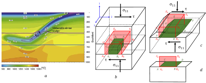
the earthquakes are caused by instability due to phase transformation (PT) from the subducted metastable -olivine (forsterite) to denser -spinel (wadsleyite) or -spinel (ringwoodite) [7, 6, 3, 1, 8, 4, 10, 2, 5, 9]
(Figs. 1a and S7).
Self-organized ellipsoidal transformed regions (anticracks) filled with nanograined product phase with very low shear resistance and orthogonal to the largest normal stress were considered. A set of anticracks aligned along the maximum shear stress reduces shear resistance and causes a shear band. In [14, 15], the acoustic emission approach was pioneered to detect ”seismic” events during several PTs, which was interpreted in favor of PT and shear instability hypotheses of the earthquake initiation. However, these semi-qualitative approaches cannot resolve puzzles mentioned in the abstract.
Plastic strain-induced phase transformations
It is clear that to obtain such jumps in plastic flow and PT rates in some rare cases, theory should contain singularity that strongly depends on some external conditions. To resolve the problem, we will utilize the main concept of high-pressure mechanochemistry
[16, 17, 18, 13].
Our first point is that
in all previous geophysical papers [7, 6, 3, 1, 8, 4, 10, 2, 5, 9], pressure- and stress-induced PTs were considered a mechanism for initiating the shear instability.
These PTs start at crystal defects that naturally exist in material and for stresses below
the yield strength. These defects (e.g., various dislocation
structures or grain boundaries) produce stress concentrators
and serve as nucleation sites for a PT. Since a number of such defects is limited, one has to increase pressure to activated defects with smaller stress concentration. In contrast, plastic strain-induced PTs take place by
nucleation at defects produced in the course of plastic flow. The largest concentration of all stress components can be produced at the tip of the dislocation pileups, proportional to the number of dislocations in a pileup. Since , local stresses could be huge and exceed the lattice instability limit, leading to nucleation of spinel during . Due to a strong reduction of stresses away from the defect tip, growth is very limited. Thus, the next plastic strain increment leading to new defects and new nuclei at their tips is required to continue PT.
That is why time is not a governing parameter in a kinetic equation, and plastic strain plays a role of a time-like parameter (see Eq.(4)).
Arrested growth also explains nanograin structure after strain-induced PTs in various systems [12, 22, 20, 21], including olivinespinel
[23, 3, 5, 10]. The important
point is that the deviatoric (nonhydrostatic) stresses in the nanoregion near the defect tip are not bounded by the engineering yield strength but rather by the ideal strength in shear for a defect-free lattice which may be higher by a factor of 10 to 100. Local
stresses of such magnitude may result in the nucleation of the high-pressure phase at an applied pressure that is not only
significantly lower than that under hydrostatic loading but also below the phase-equilibrium pressure. For example,
plastic strain-induced PT from graphite to hexagonal and cubic diamonds at room temperature was obtained at 0.4 and 0.7 GPa,
50 and 100 times below than under hydrostatic loading, respectively, and well below the phase equilibrium pressure of 2.45 GPa [12]
(see other examples for PTs in Zr, Si, and BN [24, 25, 21, 20]). In addition, such
highly-deviatoric stress states with large stress magnitudes cannot be realized in bulk. Such unique stresses may lead to
PTs into stable or metastable phases that were not or could not be attained in bulk under hydrostatic or quasi-hydrostatic
conditions [20, 27, 21, 26].
It was concluded in [16, 17, 18, 13] that plastic strain-induced
transformations require very different thermodynamic,
kinetic, and experimental treatments than pressure- and
stress-induced transformations.
Strain-induced character of PTs is consistent with results in [23, 3, 5], where metastable olivine Mg2GeO4 transforms into spinel in the 70 nm thick shear band, partially transforms in the surrounding band of few thick, and does not transform away from the band. These thin planar layers of strain-induced nanograined (10-30 nm) Mg2GeO4 spinel within olivine were observed in [23, 3] after laboratory experiment and suggested as an additional to anticrack mechanism of shear weakening. They appear along the specific slip planes, are related to dislocation pileups, and correspond to our model’s prediction below. The lower temperature is, the more strain-induced planar spinel bands and less stress-induced spinel anticrack regions are observed, consistent with promoting effect of strain-induced defects. Relative slip along a 70 nm thick transformed planar layer is 3 microns, i.e., shear strain ; slip rate is , thus and time of sliding (and PT) is . These bands offset multiple non-transforming pyroxene crystals, which allows determining relative slip. In contrast to anticracks that are mostly orthogonal to the compressive stress, transformation bands are mostly under with some scatter to the compression direction, i.e., they coincide with planes with maximum shear stress, or pressure-dependent resolved shear stress. In nature, the Punchbowl Fault also exhibited a few-mm thick slip zone, along which slip occurred by several kilometers, which contains nanograins [3, 5], i.e., shear strain . Similar strain-induced PTs and reactions are observed at the surface layers in friction experiments [3, 5].

The suggested mechanisms of localized thermoplastic flow and PT consist of several interrelated steps shown in Fig. 2 and will be elaborated below.
Mechanisms and conditions of localized thermoplastic flow and heating
According to [28], seismicity in the transition zone correlates with the rate of plastic flow, which is in the range of
.
Orthorhombic olivine has only three independent slip systems set, i.e., less than five required for the accommodation of arbitrary homogeneous deformation. That is why other mechanisms like grain-boundary migration through disclination motion [29], amorphization [30], dislocation climb, diffusive creep, and other isotropic mechanisms with linear flow rule [31, 32] supplement dislocation plasticity and control strain rate. Less than 40% of olivine aggregate strain at high temperatures may be accommodated by dislocation activity. However, when one of the slip system is aligned along or close to maximum shear stress, faster shear-dominated deformation is possible controlled solely by dislocations. Especially, slip system has critical shear stress of 0.15 MPa, at least 3 times lower
than that for all other systems (at 405 km depth, , , equivalent plastic strain rate ) [32]. Thus, if some group of grains is oriented with slip system along the maximum shear stress,
dislocation glide may occur compatible with shear strain localization due to orientational softening.
Despite the variety of deformation mechanisms, plastic flow in olivine and spinel is formally described by
| (1) |
where , is the activation energy, is the gas constant, and is the differential stress, which is the same within and outside of the shear band due to continuity of shear stresses along the band boundary. Since for olivine [33, 32], reduction in resistance by a factor of 3 leads for the same stress to increase in the strain rate by a factor of 47. Also, in Earth, olivine is mixed with diopside, which has much higher critical shear stresses, 7.31-64.7 MPa at the same conditions[32]. Thus, shear localization should start in the region with small diopside content, which may also increase strain rate by additional one-two orders of magnitude. In total, when both proper alignment of olivine grains and small diopside content are combined, local strain rate may increase by up to times without a change in temperature and reach . At such a strain rate, shear localization may be promoted by plastic heating in a band with the width exceeding to [33], but a characteristic time of this localization, to years, is way too long to resolve puzzles mentioned in abstract, and too broad to reproduce a few-mm thick slip zone in the Punchbowl Fault [3, 5]. Also, such a slow heating increase chances for slow and nonlocalized olivine-spinel PT, which eliminates the possibility of fast and localized PT and TRIP described in the next section.
In addition, we can include softening due to the substitution of olivine to a weaker nanograined spinel in a band. The initial yield strength in compression of the transformed nanograined -spinel at is 4.7 times lower than that for olivine [34]. According to Eq.(1), this leads to an additional increase is strain rate for the same stress by a factor of . Assuming that at a higher strain rate increase in stress in slightly higher, , we obtain . However, we have to exclude a factor of 47 due to orientational softening of olivine (because a factor of 4.7 is in comparison with normal olivine), leading to an additional increase by a factor of and strain rate of . Thus, in contrast to [3, 5], weak nanograined spinel, while significantly reducing resistance to shear, increases strain rate less than by a factor of . Anticracks filled with weaker nanograined spinel along the path of a shear band also reduce strength (the main softening mechanism suggested in [6, 3, 1, 5]), but much less than the above estimate when nanograined spinel is located within the entire shear band; that it why we will not consider them.
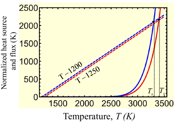
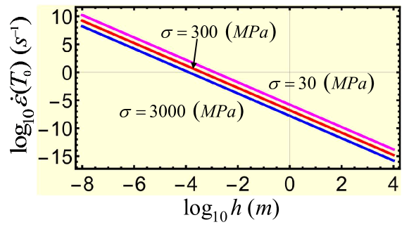
We assume that the initial temperature of the cold slab is [34], cold enough to avoid stress-induced olivine-spinel PT in a bulk, and show that to get the desired jump in the strain rate, the final temperature should be . Indeed, taking from [33] we obtain from Eq.(1) that at the strain rate increases by a factor of (Fig. 3(a)). Thus, if initial strain rate in the localized region was , then after heating to it increases to . These numbers are close to strain rates of for -spinel at 17 GPa, 1800 K, and grain size of that can be estimated from Fig. S10 in [34].
The temperature evolution equation in a localized shear band with the thickness and temperature within the rest of the material with temperature is
| (2) |
where is the mass density, is the specific heat, and is the thermal conductivity. The term is the heat flux through two shear-band surfaces due to temperature gradient , similar to [33], and Eq.(1) was used to calculate plastic dissipation. The thermal conductivity [33], where is the thermal diffusivity, , and . Constant is determined from Eq.(1) as . Then the stationary solution of Eq.(2) (i.e., ) is determined from
| (3) |
Since the Punchbowl Fault exhibited a few-mm thick slip zone [3, 5], we assume . We also choose [33, 34].
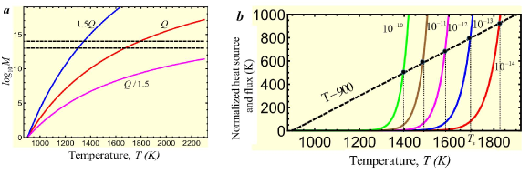
Plots of both sides of Eq.(3) in Fig. 3(b) shows that there are two stationary solutions. One of the solutions with is stable since any fluctuational increase (decrease) in temperature within a band leads to higher (lower) heat flux from the band than the plastic dissipation. The second solution varies from to when strain rate reduces from to . The higher combination is, the lower the stationary temperature is. This solution is unstable since any fluctuational increase (decrease) in temperature within a band leads to higher (lower) plastic dissipation than the heat flux from the band and further increase (decrease) in temperature. This means that (a) localized increase in strain rate and temperature in a thin band is impossible, and temperature increase estimated with neglected heat flux term to justify melting [35] or low shear resistance [3, 5] are wrong (see Supplementary Information); (b) some very significant additional heating source than the traditional plastic flow is required to reach ; otherwise the temperature will be close to ; (c) after reaching , plastic dissipation will lead to unlimited heating up to melting temperature with a corresponding drastic increase in the strain rate. Thus, even if the entire olivine would transform everywhere to much weaker nanograined spinel (not just in selected anticracks) and softening due to small content of other strong phases (which were not included in the previous models) are present, still, strain rate cannot exceed , which cannot cause a localized temperature increase.
Note that the transformation heat for olivine-spinel PT increases temperature by only [36], which is too small to reach .
Below, we suggest PT- and TRIP-related mechanisms of increase in temperature above .
Plastic strain-induced phase transformation olivinespinel and TRIP
Usually, during a PT, spinel appears as a continuous film
along grain boundaries with increasing thickness [37] or as anticrack region nucleated at the grain boundaries [23, 3, 5]. Transition to dislocation plasticity should lead to dislocation pileups and strain-induced PT within grains, which is consistent with band-shaped spinel regions observed within grains in
[23, 3, 5] and related to dislocation pileups.
Large overdrive and nonhydrostatic stresses promote martensitic PT at dislocations within grains [38, 39].
Shear stresses at the tip of the dislocation pileup should also change a slow reconstructive mechanism of olivine-spinel PT to a fast martensitic mechanism. Transformation bands include planes, which include slip system with the smallest critical stress,
see [32], consistent with our assumption above. However, there are also transformation bands, which do not have smaller critical shear stress and do not lead to the orientational softening. That means that orientational softening is not a mandatory
mechanism for initial localization and can be compensated by smaller diopside content along those planes.
Strain-controlled kinetic equation [16, 17] for the volume fraction of the strain-induced high-pressure phase simplified in Supplementary Information is
| (4) |
Here, and are the minimum pressure at which the direct (i.e., to high-pressure phase) strain-induced and pressure-induced PTs are possible, respectively, and is a parameter. We do not consider strain-induced reverse spinelolivine PT, because resultant nanograin spinel deforms dominantly by grain-boundary sliding, which does not produce stress concentrators inside the grains. The first experimental and only existing confirmation of Eq.(4) and parameter identification were performed for PT in Zr [25]. Based on data, for , which we will used due to lack of data for olivinespinel PT. In contrast to pressure/stress-induced PT, time is not a parameter in Eq.(4), plastic strain plays a role of a time-like parameter. Thus, the rate of strain-induced PT is determined by the rate of plastic deformation. To reach , plastic strain , which at strain rate (or ) takes just (or ), instead of millions years without plastic strain. Thus, plastic strain can increase the transformation rate by more than ten orders of magnitude.
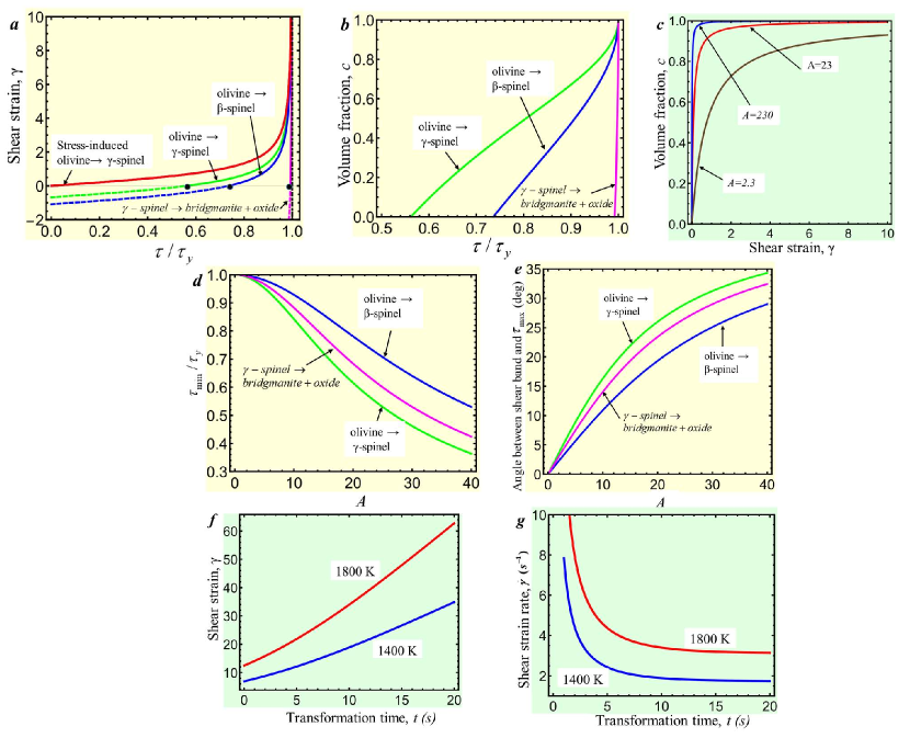
Next, we need to find a mechanism for a drastic increase in strain rate and temperature. We suggest that TRIP caused by olivinespinel PT can cause this. TRIP occurs due to internal stresses caused by volume change during the PT combined with external stresses. We found (Supplementary Information) an analytical 3D solution, in which the plastic shear , which is TRIP, is related to the applied shear stress , the yield strength in shear during PT, and volumetric transformation strain (see Fig. 4(a)) as
| (5) |
Effective transformation volumetric strain during growth of forces plastic strain to restore displacement continuity across an interface (see Fig. 1(b) and (c)), and plastic flow takes place at arbitrary (even infinitesimal)
shear stress. The yield strength in shear during PT is unknown. Atomistic simulations for many materials (e.g., in [12, 40])
show that lattice resistance drops to and even below zero after lattice instability. For strain-induced PT, nanosize nuclei also reduce the yield strength [34]. We assume that .
For (e.g., in a shear band), plastic shear tends to infinity (Fig. 4(a)).
This is the desired singularity we wanted to find above. Note that our 3D solution has the proportionality factor times larger
than in the previous 2D treatments [41, 42, 44, 43], which changes the current results qualitatively.
Self-blown-up deformation-transformation-heating process
Since PT causes TRIP, which (like traditional plasticity) promotes strain-induced PT, it, in turn, promotes TRIP, and so on, there is positive thermomechanochemical feedback, which we called a self-blown-up deformation-transformation-heating process.
In such a case, Eq.(4) cannot be integrated alone but should be considered together with Eq.(5).
For shear-dominated flow , and we obtain (Fig. 4(a)-(d))
| (6) |
| (7) |
Eq.(7) is the criterion for a self-blown-up deformation-transformation-heating process, shown in Fig. 4(d) vs. . It is obtained from Eq.(6) and condition or . The last expression for in Eq.(6) is obtained by excluding from two previous Eqs.(6). For olivine-spinel PT and for olivine-spinel PT [45, 2]; this results in for -spinel and for -spinel, which are not very restrictive. Thus, since , where is the angle between maximum shear stress and shear band, the above criterion is met at for -spinel and for -spinel (Fig. 4(e)). We will focus on olivine-spinel PT since it has larger TRIP and less restrictive constraints.
To have , and ; for , and . Thus, for the self-blown-up deformation-transformation process to produce shear , one needs , i.e., perfect alignment of maximum shear stress and shear band. This contributes to understanding why the self-blown-up deformation-transformation-heating process and deep-focus earthquakes are relatively rear processes. Eq. (7) explains extremely large shear strains (sliding) in a fault or friction surface. Also, since deviatoric shear strain is much larger than , this resolves a puzzle of the deviatoric character of the deep-earthquake source [11, 9]. Note that for very large TRIP shear the term in Eq.(6)2 is negligible (Fig. 4(a)), i.e., TRIP shear is independent of any kinetic properties of strain-induced PT. Also, for , Eq.(6)2 gives . TRIP-induced temperature rise is determined by the equation
| (8) |
in which for we even neglected the transformation heat to have a conservative estimate. The solution is
| (9) |
where is the stationary temperature due to TRIP heating. The shear rate to reach temperature during the PT time , as well as corresponding hear strain are determined from Eq.(9)
| (10) |
Figs. 4(f) and (g) exhibit and required to reach temperatures and vs. transformation time for parameters for the Punchbowl Fault. The faster PT is, the smaller shear but larger strain rates are required. Minimum shears are at (instantaneous PT), and but results in infinite strain rate. For , the desired temperature is reached during transitional heating. For , it is reached by approaching a stationary temperature; that is why the required strain rates approach stationary values. Based on kinetic estimates in [34], time for complete pressure-induced PT at and is ; strain-induced PT may occur by orders of magnitude faster even at a much lower temperature. Practically, limitation comes from the required shear (rather than shear rate). Based on Eq.(6), strain requires , i.e., practically perfect alignment of the shear band along the maximum shear direction. Shear rate is calculated by dividing shear by PT time. For , shear rate is smaller than , and after completing PT it further increases during traditional plastic flow due to (Fig. 3(b)). For , the shear rate is in the range of , on the same order of magnitude as it is expected at during traditional plastic flow.
Note that since during PT , traditional plastic flow (which is neglected) should add to TRIP and further increase both strain rate and temperature. Thus, TRIP and the self-blown-up deformation-transformation-heating process should lead to temperatures higher than in Fig. 3, after which further drastic temperature increase does not need PT and can occur due to traditional plastic flow. Theoretically, thermoplastic unstable temperature increase above can lead to melting, which is one of the mechanisms of high-strain rate shear localization and deep earthquake [11, 35]. However, due to a strong heterogeneity of earth materials along the shear band, including nontransforming minerals, melting may not be reached and is not necessary. As it is estimated above, reaching is sufficient for achieving strain rates . We also want to stress that the melting-based mechanism of the deep earthquake is possible in nature only if some other processes (like self-blown-up deformation-transformation-heating) will increase temperature above (see Supplementary Information).
For laboratory experiments in [3], due to very small thickness of the transformation-deformation band, temperature increase due to TRIP is negligible even for (Supplementary Information). That means that after completing PT, strain rate should reduce to the value corresponding to nanograined spinel under the same stress and temperature, which is , and its contribution to the total shear is small. Thus, this strain is due to TRIP only. Since in the Punchbowl Fault , the major part of this strain is due to thermoplastic flow after PT and above .
Similar processes are expected in multiple transformation-shear and shear bands (Fig. 2) that find ways through weak obstacles and may percolate or just increase the total shear-band volume and amplify generated seismic waves.
In reality, the shear band is not infinite but has a very large (10 to 1000 and larger) ratio of length, at least in the shear direction, to the width. That is why the above theory is applicable away from the boundary of a band. When finite-size single or coalesced deformation or transformation-deformation bands propagate, stresses at their ends are equivalent to those at a dislocation pileup or superdislocation but at a larger scale [46] and with the total Burgers vector , which may be huge. These stresses cause both fast PT and plasticity and further propagation of shear band and trigger initiation of new bands, mostly mutually parallel. Such a stress concentrator is by a factor of , i.e., orders of magnitude, stronger than that at the tip of the anticrack [6, 23, 3, 1, 8, 4, 2, 5] and much more effective in spreading transformation-deformation bands at the higher, microscale. The resulting propagating thermoplastic band can pass through non-transforming minerals and extend outside of metastable olivine wedge. Indeed, it was demonstrated in [5] that the fault originated in metastable Mg2GeO4 olivine during its transformation to spinel propagated through previously transformed spinel.
To summarize, our quantitative mechanisms of very fast localized thermoplastic flow and PT consist of several interrelated steps shown in Fig. 2 and contain several conceptually important points: (a) Proof that plastic flow alone cannot lead to localized in mm-scale band heating, that is why PT is required; (b) Substitution of stress-induced PT with plastic strain-induced PT, which was not previously used in geophysics and leads to completely different kinetic description; (c) Transition to dislocation flow with strong stress concentrators is required to substitute stress-induced PT with barrierless and fast plastic strain-induced PT; (d) Strain-induced PT in a shear band generates severe (singular) TRIP and heating, which in turn produces strain-induced PT and so on, resulting in the self-blown-up PT-TRIP-heating process due to positive thermomechanochemical feedback. (e) This leads to the heating above the temperature, exceeding unstable stationary temperature , after which further heating in a shear band occurs due to traditional thermoplastic flow. Achieving is sufficient to reach and generate seismic waves. (f) These processes repeat themselves at larger scale.
Lack of any of these processes due to not meeting the required conditions (e.g., proper orientation or path with a small content of stronger phases) may lead to inability to reach very fast localized PT and plastic flow and cause an earthquake, which explains that earthquakes are relatively rare events. Similarly, lack of seismic activity below 660 km, where endothermic and slow disproportionation reaction from -spinel to bridgmanite)+ oxide (magnesiowüstite) occurs, can be explained (see Supplementary Information).
Relatively small shear strain in laboratory experiment [23] ( vs. in nature) is because the temperature cannot grow due to an extremely thin band, processes in the third column in Fig. 2 are absent, and TRIP occurs only (see Supplementary Information). A very rare occurrence of such bands in a laboratory is related to small sample size and low probability of realization of sequences of all the processes in Fig. 2, as well as to small temperature window when stress-induced anticrack cannot appear but strain-induced bands can. Our Eq.(1) relates the change in strain rate with respect to the initial one before localization. That is why the final strain rate is distributed with depth similar to the initial strain rate before localization. This is consistent with the correlation between seismicity in transition zone and strain rate before localization [28]. Eq. (7) explains extremely large shear strains (sliding) in a fault or friction surface. Since shear strain is much larger than the volumetric strain, this resolves a puzzle of the deviatoric character of the deep-earthquake source [11, 9].
Our findings change the main concepts in studying the initiation of the deep-focus earthquakes and PTs during plastic flow in geophysics in general. They will be elaborated in much more detail using modern computational multiscale
approaches for studying coupled PTs and plasticity [13]. Introducing strain-induced PT and the self-blown-up transformation-TRIP-heating process
may change the interpretation of various geological phenomena.
In particular, they may explain
possibility of the appearance of microdiamond directly in the cold Earth crust within shear bands [12] during tectonic activities without subduction to the high-pressure and high-temperature mantle and uplifting. Developed theory of the self-blown-up transformation-TRIP-heating process is applicable outside geophysics for various processes in materials under pressure and shear, e.g., for new routes of material synthesis, friction and wear under high load, penetration of the projectiles and meteorites, surface treatment, and severe plastic deformation and mechanochemical technologies [16, 17, 26, 18, 13, 48, 47, 49, 50].
Acknowledgements.
Support from
NSF (CMMI-1943710 and DMR-1904830), and Iowa State University (Vance Coffman
Faculty Chair Professorship) is greatly appreciated.
References
- [1] Green, H.W. & and Burnley, P.C. A new, self-organizing, mechanism for deep-focus earthquakes. Nature, 341, 773-737 (1989).
- [2] Green II H. W. Shearing instabilities accompanying high-pressure phase transformations and the mechanics of deep earthquakes. Proc. Natl Acad. Sci. USA, 104, 9133-9138 (2007).
- [3] Green II, H. W. , Shi F., Bozhilov, K., Xia G., & Reches, Z. Phase transformation and nanometric flow cause extreme weakening during fault slip. Nature Geoscience, 8, 484-489 (2015).
- [4] Schubnel, A., Brunet, F., Hilairet, N., Gasc, J., Wang, Y. & Green, H.W. Deep focus earthquake analogs recorded at high pressure and temperature in the laboratory. Science, 341, 1377–1380 (2013).
- [5] Green, II H. W. Phase-transformation-induced lubrication of earthquake sliding. Phil. Trans. R. Soc. A, 375 20160008 (2017).
- [6] Burnley, P.C. & Green II, H.W. Stress dependence of the mechanism of the olivine-spinel transformation. Nature, 338, 753-756 (1989).
- [7] Kirby, S. Localized polymorphic phase transformations in high-pressure faults and applications to the physical mechanism of deep earthquakes. J. Geophys. Res., 92, 13, 789-800 (1987).
- [8] Kirby, S.H., Stein, S., Okal, E. A. & Rubie, D. C Metastable mantle phase transformations and deep earthquakes in subducting oceanic lithosphere. Rev. Geophys., 34, 261–306 (1996).
- [9] Zhan, Z. Mechanics and implications of deep Earthquakes. Annu. Rev. Earth Planet. Sci., 48, 147-174 (2020).
- [10] Wang, Y., Zhu, L., Shi, F., Schubnel, A., Hilairet, N., Yu, T., Rivers, M., Gasc, J., Addad, A., Deldicque, D., Li, Z. & Brunet, F. A laboratory nanoseismological study on deep-focus earthquake micromechanics. Sci. Adv. 3, e1601896 (2017).
- [11] Frohlich, C. The nature of deep-focus earthquakes. Annu. Rev. Earth Planet. Sci., 17, 227–254 (1989).
- [12] Gao, Y., Ma, Y., An, Q., Levitas, V. I., Zhang, Y., Feng, B., Chaudhuri, J. & Goddard, III W. A. Shear driven formation of nano-diamonds at sub-gigapascals and 300 K. Carbon, 146, 364-368 (2019)
- [13] Levitas, V.I. High-Pressure Phase Transformations under Severe Plastic Deformation by Torsion in Rotational Anvils. Material Transactions, 60, 1294-1301 (2019).
- [14] Meade, C. R. & Jeanloz, R., Acoustic emissions and shear instabilities during phase transformations in Si and Ge at ultrahigh pressures. Nature, 339, 616-618 (1989).
- [15] Meade, C. & Jeanloz, R. Deep-focus earthquakes and recycling of water into Earth’s mantle. Science 252, 68-72 (1991).
- [16] Levitas, V.I. Continuum Mechanical Fundamentals of Mechanochemistry. In: High Pressure Surface Science and Engineering, eds. Y. Gogotsi and V. Domnich, Institute of Physics, Bristol, Section 3, 159-292 (2004)
- [17] Levitas, V. I. High-Pressure Mechanochemistry: Conceptual Multiscale Theory and Interpretation of Experiments. Phys. Rev. B, 70, 184118, 1-24 (2004)
- [18] Levitas, V. I. High pressure phase transformations revisited. Invited Viewpoint article. Journal of Physics: Condensed Matter, 30, 163001 (2018).
- [19] Kawakatsu, H. & Yoshioka, S. Metastable olivine wedge and deep dry cold slab beneath southwest Japan. Earth and Planetary Science Letters, 303, 1-10 (2011).
- [20] Ji, C., Levitas, V. I., Zhu, H., Chaudhuri, J., Marathe, A. & Ma, Y. Shear-Induced Phase Transition of Nanocrystalline Hexagonal Boron Nitride to Wurtzitic Structure at Room Temperature and Low Pressure. Proceedings of the National Academy of Sciences of the United States of America, 109, 19108-19112 (2012).
- [21] Blank, V. D. & Estrin, E. I. Phase Transitions in Solids under High Pressure, CRC Press, Boca Raton (2014)
- [22] Levitas, V. I., Ma, Y., Hashemi, J., Holtz, M. & Guven, N. Strain-induced disorder, phase transformations and transformation induced plasticity in hexagonal boron nitride under compression and shear in a rotational diamond anvil cell: in-situ X-ray diffraction study and modeling. Journal of Chemical Physics, 25, 044507(1-14) (2006)
- [23] Riggs, E & Green, II H. W. A new class of microstructures which lead to transformation-induced faulting in magnesium germanate. J. Geophys. Res. 110, B03202 (2005).
- [24] Levitas, V. I. & Shvedov, L. K. Low Pressure Phase Transformation from Rhombohedral to Cubic BN: experiment and theory. Phys. Rev. B, 65, 104109 (2002).
- [25] Pandey, K. K. & Levitas, V. I. In situ quantitative study of plastic strain-induced phase transformations under high pressure: Example for ultra-pure Zr. Acta Materialia, 196, 338-346 (2020).
- [26] Edalati, K. & Horita, Z. A review on high-pressure torsion (HPT) from 1935 to 1988, Mat. Sci. Eng. A., 652, 325–352 (2016).
- [27] Levitas, V. I., Ma, Y., Selvi, E., Wu, J. & Patten, J. A. High-density amorphous phase of silicon carbide obtained under large plastic shear and high pressure. Physical Review B, 85, 054114 (2012).
- [28] Billen, M. I. Deep slab seismicity limited by rate of deformation in the transition zone. Science Advances 6, eaaz7692 (2020).
- [29] Cordier, P., Demouchy, S., Beausir, B., Taupin, V., Barou, F. & Fressengeas, C. Disclinations provide the missing mechanism for deforming olivine-rich rocks in the mantle. Nature, 507, 51-56 (2014).
- [30] V., Samae, P., Cordier, S., Demouchy, C., Bollinger, J. Gasc, S. Koizumi, A. Mussi, D., Schryvers, & H., Idrissi Stress-induced amorphization triggers deformation in the lithospheric mantle. Nature, 591, 82–86 (2021).
- [31] Hirth, G. & Kohlstedt, D. L. Experimental constraints on the dynamics of the partially molten upper-mantle. 2. Deformation in the dislocation creep regime. J. Geophys. Res. 100, 15441–15449 (1995).
- [32] Raterron, P., Detrez F, Castelnau, O., Bollinger, C., Cordier, P., & Merkel, S. Multiscale modeling of upper mantle plasticity: From single-crystal rheology to multiphase aggregate deformation. Physics of the Earth and Planetary Interiors 228, 232-243 (2014).
- [33] Ogava M. Shear Instability in a Viscoelastic Material as the Cause of Deep Focus Earthquakes. J. Geophysical Research, 92, 801-810 (1987).
- [34] Mohiuddin, A., Karato, S.-I., & Girard, J. Slab weakening during the olivine to ringwoodite transition in the mantle. Nature Geoscience, 13, 170-174 (2020).
- [35] Kanamori, H., Anderson, D.L. & Heaton, T.H. Frictional melting during the rupture of the 1994 Bolivian earthquake. Science 279, 839–842, (1998).
- [36] Sung, C-M. & Burns R. G. Kinetics of high-pressure phase transformations: implications to the evolution of the olivine spinel transition in the downgoing lithosphere and its consequences on the dynamics of the mantle. Tectonophysics, 31, 1-32 (1976).
- [37] Mohiuddin, A. & Karato, S. An experimental study of grain-scale microstructure evolution during the olivine–wadsleyite phase transition under nominally “dry” conditions. Earth Planet. Sci. Lett. 501, 128–137 (2018).
- [38] Poirier, J.-P. Introduction to the Physics of the Earth’s Interior. Cambridge University Press (2000).
- [39] Smyth, J. R., Miyajima, N., Huss, G. R., Hellebrand, E., Rubie, D. C., & Frost, D. J. Olivine–wadsleyite–pyroxene topotaxy: Evidence for coherent nucleation and diffusion-controlled growth at the 410-km discontinuity. Physics of the Earth and Planetary Interiors, 200-201, 85–91 (2012).
- [40] Zarkevich, N. A., Chen, H., Levitas, V. I. & Johnson D. D. Lattice instability during solid-solid structural transformations under general applied stress tensor: example of Si I Si II with metallization. Physical Review Letters, 121, 165701 (2018).
- [41] Levitas, V. I. Phase Transitions in Elastoplastic Materials: Continuum Thermomechanical Theory and Examples of Control. Part I and II. J. Mech. Phys. Solids, 45, 923-947 and 1203-1222 (1997).
- [42] Levitas, V. I. Thermomechanical Theory of Martensitic Phase Transformations in Inelastic Materials. Int. J. Solids and Structures 35, 889-940 (1998).
- [43] Levitas, V. I., Nesterenko V. F. and Meyers M. A. (1998). Strain-Induced Structural Changes and Chemical Reactions. Part I and II. Acta Materialia 46, 5929-5945 and 5947-5963 (1998).
- [44] Levitas, V. I. Structural Changes without Stable Intermediate State in Inelastic Material. Part I and II. Int. J. Plasticity, 16, 805-849 and 851-892 (2000).
- [45] Navrotsky, A. Thermodynamic relations among olivine, spinel, and phenacite structures in silicates and germanates: I. Volume relations and the systems NiO-MgO-GeO2 and CoO-MgO-GeO2. Journal of Solid State Chemistry, 6, 21-41, (1973).
- [46] Levitas, V. I., Esfahani, S. E. & Ghamarian I. Scale-free modeling of coupled evolution of discrete dislocation bands and multivariant martensitic microstructure. Phys. Rev. Letters, 121, 205701 (2018).
- [47] Zharov, A. A. Reaction of Solid Monomers and Polymers under Shear Deformation and High Pressure. High Pressure Chemistry and Physics of Polymers, ed A. L. Kovarskii, Ch. 7, 267-301 (Florida: CRC Press, Boca Raton) (1994)
- [48] Koch, C. C., The Synthesis and Structure of Nanocrystalline Materials Produced by Mechanical Attricion: A Review, Nanostructured Materials, 2, 109-129 (1993).
- [49] Takacs, L. The historical development of mechanochemistry, Chem. Soc. Rev. 42, 7649-7659 (2013).
- [50] Balaz, P, et al. Hallmarks of mechanochemistry: from nanoparticles to technology, Chem. Soc. Rev. 42, 7571-7637 (2013).
- [51] Levitas, V. I., Ozsoy, I. B. Micromechanical modeling of stress-induced phase transformations. Part 1. Thermodynamics and kinetics of coupled interface propagation and reorientation. Int. J. Plasticity, 25, 239-280 (2009).
- [52] Truesdell, C. & Toupin, R.A. The classical field theories. In Handbuch der Physik III/1, ed S. Flügge (Berlin: Springer) (1960).
- [53] Ottonello, G., Civalleri, B., Ganguly, J., Zuccolini, M.V., Noel,Y. Thermophysical properties of the polymorphs of Mg2SiO4: a computational study. Phys Chem Minerals, 36, 87–106 (2007).
- [54] Gleason, G. & Green, II HW. A general test of the hypothesis that transformation-induced faulting cannot occur in the lower mantle. Phys. Earth Planet Inter, 172, 91–103 (2009).
- [55] Takacs, L., Self-sustaining reactions induced by ball milling, Progress in Materials Science, 47, 355-414 (2002).
- [56] Green, II H.W., Shi, F., Bozhilov, K.N., Xia, G. & Reches, Z. 2015 Phase transformation and nanometric flow cause extreme weakening during fault slip. Nat. Geosci. 8, 484–489 (2015).
- [57] Frohlich, C. Deep Earthquakes. Cambridge University Press, Cambridge, UK (2006).
- [58] Karato, S., Riedel, M. R. & Yuen, D.A. Rheological structure and deformation of subducted slabs in the mantle transition zone: implications for mantle circulation and deep earthquakes. Physics of the Earth and Planetary Interiors, 127, 83–108 (2001).
- [59] Kulnitskiy, B. A., Blank, V. D., Levitas, V. I., Perezhogin, I. A., Popov M., Y., Kirichenko, A. N. & Tyukalova, E. V., Transformation-deformation bands in C60 after the treatment in a shear diamond anvil cell. Materials. Res. Express, 3, 045601 (2016).
- [60] Markenscoff, X. “Volume collapse” instabilities in deep-focus earthquakes: A shear source nucleated and driven by pressure. J. Mech. Phys. Solids, 152, 104379 (2021).
- [61] Levitas, V.I. Idesmanm A.V., Olson, G.B. & Stein, E. Numerical Modeling of Martensite Growth in Elastoplastic Material. Philosophical Magazine, A, 82 (3), 429-462 (2002).
Supplementary Information
Resolving puzzles of the phase-transformation-based mechanism of the deep-focus earthquake
Valery I. Levitas
Iowa State University, Departments of Aerospace Engineering and
Mechanical Engineering, Ames, Iowa 50011, USA
Ames Laboratory,
Division of Materials Science and Engineering, Ames, IA, USA
1 Kinetics of plastic strain-induced phase transformations
The strain-controlled kinetic equation derived in [17, 16] using the main conceptual results from the nanoscale modeling of nucleation at the dislocation pileup and micromechanical treatment is
| (11) |
Here, is the pressure, is the volume fraction of a high-pressure phase, is the yield strength of -th phase; and are the minimum pressure at which the direct strain-induced phase transformation (PT) may occur and maximum pressure at which the reverse strain-induced PT proceeds, respectively, is the Heaviside step function used to impose criteria for the direct () and reverse () strain-induced PTs; and are the pressures for the direct and reverse PTs under hydrostatic loading; symbols , , , and are material parameters. Eq.(11) includes the possibility of direct and reverse PTs and the different plastic strain in each phase due to different .
We do not consider strain-induced reverse spinelolivine PT because resultant nanograin spinel deforms dominantly by grain-boundary sliding, which does not produce stress concentrators inside the grains. The difference in yield strength of phases is neglected for compactness and . Then Eq.(11) reduces to
| (12) |
which is Eq. (4) in the main text.
2 Analytical 3D solution for transformation induced plastic shear in a transformation-shear band
To model the transformation-deformation band in olivine, we consider an infinite space within which localized plastic deformation and PT occur (Fig. 5). TRIP occurs due to internal stresses caused by volume change during the PT combined with external stresses. We found simple analytical solutions for PT in a plastic shear band at small [41, 44] and large [43] strains in the 2D formulation. Here, we find the first 3D analytical solution.
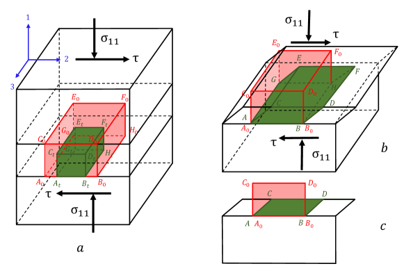
We consider the homogeneous state of the space and band before strain localization and phase transformations as the reference state. Then change in elastic strains is small and can be neglected. Thermal strains are also minor compared to plastic and transformational strains and will be neglected as well. Deformations outside the band are negligible, i.e., rigid space is considered. The stress-strain state within the band is homogeneous. For compactness and transparency, we will use small-strain formalism, while the final results will be valid for large plastic and small transformational strains, which is the case for olivine-spinel PT (volumetric transformation strain for complete PT ) and for olivine-spinel PT ()[45, 2].
Let us choose the orthogonal coordinate system with axis 1 directed along the normal to the shear band and axes 2 and 3 parallel to the shear band. We divide six components of any symmetric tensor, e.g., stress , into two parts:
| (22) |
Components are stresses acting at the surface of the shear band, i.e., components of the traction vector; components are in-band stresses. Also, we chose axis 2 along the applied shear stress , i.e., . Components within the band are equal to corresponding components in the space due to traction continuity conditions. Then they are equal to applied stresses and are considered independent of time during phase transformation.
The total strain consists of plastic and transformational parts:
| (32) |
where transformation strain is a spherical (pure volumetric) tensor. Decomposing Eq.(32) in normal and in-band parts, we obtain
| (42) |
| (52) |
Due to continuity of displacements across the shear-band boundary and rigid space outside the band (i.e., the coherent boundary between shear-band and the rest of the space), we obtain
| (56) |
Eq.(56), which was derived in [42, 51], directly follows from the Hadamard compatibility condition [52] across a coherent boundary. Geometrically, it means that the boundary is undeformed and, due to homogeneity of the strain state within a band, in-band strains are absent.
It follows from Eq.(56) and the plastic incompressibility
| (57) |
The von Mises yield condition
| (58) |
where and are the yield strengths in compression and shear, respectively, is the deviatoric stress, and is the unit tensor. The yield strength during PT is unknown, and based on the discussion in the main text, we will consider it a constant. Associated with the von Mises yield condition plastic flow rule is the proportionality between plastic strain rate and deviatoric stress tensors:
| (65) |
where is the proportionality factor. It follows from Eq.(65)
| (66) |
Designating and utilizing Eq.(66), plastic flow rule simplifies to
| (73) |
Eq.(73) contains just two independent equations
| (74) |
To exclude , we utilize the plasticity condition Eq.(58)
| (75) |
Substituting Eq.(75) in Eq.(74), we obtain
| (76) |
Since during PT the volumetric transformation strain is , where is the volume fraction of spinel, then , and Eq.(76) takes its final form
| (77) |
Eq.(77) represents an explicit expression for plastic shear strain rate induced by PT, i.e., TRIP shear. During both direct and reverse PT, TRIP shear increases independent of the sign of the volumetric transformation strain is . While Eq.(77) has the same form as previous 2D solutions, the proportionality factor is times larger than for 2D treatment. Eq.(77) is used as Eq. (5) in the main text.
For completeness, pressure is determined from the equation
| (78) |
3 Heat transfer analysis of laboratory experiments [23, 3]
Substituting in Eq.(3) of the main text data for Mg2GeO4 from [23], namely (sample GL707), , , , and , as well as from [3], , , , and , we obtain for the first case and for the second case (see Fig. 6). Due to very small shear band thickness in the laboratory experiments, these values are extremely high, far away from the region of stability of spinel, and well above the melting temperature. Since no traces of reverse PT to olivine and melting were observed in [23, 3], these temperatures were not reached, and no thermoplastic shear localization is possible without PT, TRIP, and self-blown-up deformation-transformation-heating process.
However, even with TRIP, substituting in Eq.(9) of the main text data from the same laboratory experiment [3] , (see the main text), and maximum from Fig. S2 in [3], we obtain that the maximum (stationary) temperature increase is just . This should not be surprising because thickness in a laboratory experiment is smaller than in Earth by a factor of 57143. Since stationary temperature increment is proportional to , for , , and , it would be . Thus, in laboratory experiments on Mg2GeO4 [3] temperature increase in the transformation-shear band was absent.
In [3], adiabatic approximation was used to estimate maximum shear stress and internal friction coefficient from the condition that temperature increment does not exceed , maximum increment to reach the olivine-spinel phase equilibrium temperature. A paradoxical result was that the estimated shear stress and friction coefficient were an order of magnitude lower than directly measured. The reason for this paradox is in adiabatic approximation; when heat flux from the shear band is included, the temperature increase is negligible for any reasonable shear resistance and does not restrict the internal friction stress. This also means that the sliding should drastically reduce after completing PT; that is why shear in the Punchbowl Fault, , is drastically larger than in the laboratory, . Consequently, processes in the third column in Fig. 2 in the main text are absent in laboratory experiments and cannot be verified due to small shear band thickness.
Similarly, drastic heating leading to melting and dissociation is predicted in [35] using adiabatic approximation. When heat flux is included, conditions for melting are quite restrictive.
4 Conditions for unstable heating in the shear band due to thermoplastic flow alone
Let us rewrite Eq. (3) from the main text for the stationary temperature during plastic flow alone (i.e., without PT) in the more compact form
| (79) |
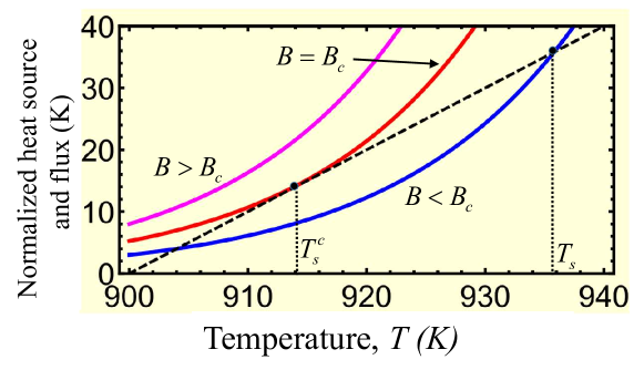
As it follows from Fig. 3(b) in the main text and Fig. 7 here, for small Eq.(79) has two solutions: one of the solutions with is stable and another one with is unstable. This means heating in the shear band for small is impossible without extra heat sources leading . With increasing , the first stable solution slightly exceeds while reduces much faster. At some critical and both solutions coincide, plastic dissipation exceeds the heat flux from the band for all temperatures (excluding ), the stationary solution is unstable, and unlimited heating occurs for any infinitesimal perturbation. For critical , derivatives of both sides of Eq.(79) coincide, i.e.,
| (80) |
Excluding exponent from Eqs. (79) and (80), we obtain a simple equation
| (81) |
with the relevant solution
| (82) |
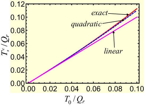
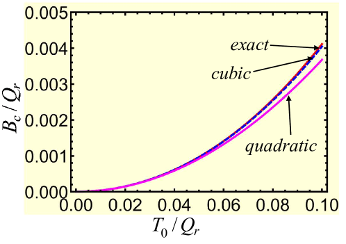
where due to the smallness of the Taylor series is used. Substituting exact from Eq.(82) in Eq. (79), we obtain critical value of :
| (83) |
where is the Euler’s number. Figs. 8 and 9 show plots for and vs. . It is clear that for , is well approximated by quadratic function and reasonably good by the linear one. The cubic approximation is not distinguishable from the exact equation. Similar is very good approximated by a cubic polynomial and reasonably good by the quadratic one.
For data that we used for the Punchbowl Fault, , , , , , - , we have and , while and , i.e., far away from the initiation of the thermoplastic instability, as expected from Fig. 3(b) in the main text.
It is convenient to present instability condition in the form
| (84) |
see Fig. 10. For the above parameters and and , the instability conditions can be satisfied for and , respectively. These parameters are in the range obtained in [33] numerically using linear perturbation analysis. Here, simple analytical expressions are derived. For the laboratory experiment on for Mg2GeO4 from [23], and , and the instability condition can be met for , which is still very large for the laboratory experiment.
Does this mean that shear-induced melting is impossible in Earth and the laboratory due to very small observed band thickness? Actually not. Let us assume that the initial shear band thickness can be much larger. This does not contradict to much smaller observed thickness after phase transformation (including melting) because PT leads to further softening and, due to heterogeneities, may occur in a very narrow part of the initial band. That is why after solid-solid PT or chemical reaction thickness of a band strongly decreases, and instability temperature cannot be reached at the laboratory scale (but can be met in nature). If PT or reaction does not occur below the melting temperature at a high strain rate, melting can be reached. Thus, taking , , we obtain critical , which may be achievable in large-volume high pressure apparatuses. Taking and , which may be reasonable for a shear band in nature, we obtain critical , which is not clear how to reach starting with after all softening mechanisms unrelated to a PT .
5 Phase equilibrium pressure-temperature diagram for olivine, -spinel, and -spinel
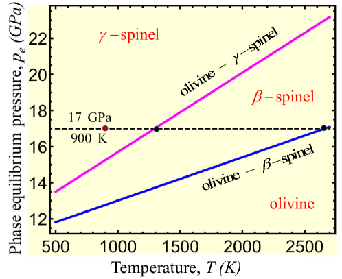
We assume that the minimum pressure for the direct PT, , grows with temperature similar to the phase equilibrium pressure , see Fig. 11. The equilibrium pressure olivine- spinel is (approximated from [53]). Then at we have , well above in Fig. 3 in the main text. The phase equilibrium pressure olivine- spinel is [53] and at we have . Since strain-induced PT may occur even much below the phase equilibrium pressure, we assume that PT olivine- spinel occurs below , the unstable stationary temperature for straining without PT for (Fig. 3 in the main text). Alternatively, PT olivine- spinel can be considered above 1295 K with slightly smaller , which does not change conclusions. Moreover, if spinel that appeared below 1295 K transforms back to the spinel, the same TRIP will take place like for spinel PT, since it is determined by .
6 Analysis of the lack of seismic activity below 660 km
Lack of any of the processes shown in Fig. 2 of the main text due to not meeting the required conditions may explain lack of seismic activity below 660 km, where endothermic and slow disproportionation reaction from ringwoodite to MgSiO3 (bridgmanite)+ (Mgx Fe1-x)O (magnesiowüstite) occurs. It is difficult to say which exactly process is missing because a counterargument may override each argument. For example, one may say that reaction, in contrast to martensitic PT, requires a diffusive mass transport, and both nucleation and growth cannot be as fast as martensitic PT, which is proved for the proxy reaction albitejadeite + coesite [54, 5]. However, this may be true or not because large plastic shears strongly accelerate mass transport and chemical reaction as well [47, 48, 43, 55, 49, 50], and it is unknown how do shears affect this specific reaction. In particular, at friction surfaces the decomposition reaction of dolomite MgCa(CO3)MgO+CaO+2CO2 completes within 0.006 s [56] with temperature increase exceeding 1000 K.
The most probable reasons are:
(a) lack of initial shear localization in nanograined spinel before reaction due to grain sliding deformation without orientational softening (which reduces by a factor of ) and reduced dislocation activity, which makes the transition to strain-induced PT and self-blown-up deformation-transformation-heating process impossible;
(b) the higher initial temperature at 660 km (see [19, 28] and Fig. 1a in the main text); e.g., increase in from 900 K to 1000 K reduces parameter in Eq.(1) in the main text by a factor of 653, and
(c) low initial strain rate below 660 km [28] reduces the final strain rate proportionally.
One of the conditions for PT-induced instability mentioned in [2, 5] is the exothermic character of the olivine-spinel PT, leading to runaway heating. At the same time, the reaction from ringwoodite to bridgmanite + magnesiowüstite is endothermic and cannot produce instability and earthquakes below 600 km. However, for coupled strain-induced PT-TRIP process, plastic heating during PT and contribution of PT heat ( [36]) in temperature increase from 900 to is small. Thus, we do not think that the exothermic character of PT alone is critical. In laboratory experiments, temperature change within the shear band is negligible.
Exothermic PT was utilized in [3] also to explain nanograined spinel structure. The temperature increase due to PT heat increases the driving force for PT and causes runaway nucleation under growth-inhibited conditions. Suppose a slight temperature increase would be the reason for a drastic increase in nucleation rate. In that case, runaway nucleation should occur everywhere rather than to localize within anticracks, especially in hotter regions of the metastable olivine slab closer to its boundary with spinel. It is also unclear why growth is slow at such a large thermodynamic driving force that causes runaway nucleation. At the same time, nucleation at dislocations and dislocations pileups leads to nanograined structure because of growth arrest due to a strong reduction of stresses away from the defect tip [16, 17, 18, 13].
7 Relation to some previous works
TRIP is well known to the geological community, but it was considered to having a small effect [57, 7, 58, 38]. This is correct in general, but for a properly oriented shear band where , plastic shear tends to infinity (see Eq.(77) and Fig. 4(a) in the main text). Shear banding and TRIP are observed in DAC experiments in fullerene [59] and BN [22] despite the PTs to stronger high-pressure phases. For PT from hexagonal to superhard wurtzitic BN, TRIP was evaluated to be 20 times larger than prescribed shear [22]. Shear banding during PT is possible if the yield strength during PT does not increase despite the high strain rate and strength of the high-pressure phase, which supports our conservative hypothesis . Positive feedback between PT and TRIP without heating was suggested in [22] but without any equations. Reaction-induced plasticity (RIP) similar to TRIP was revealed for a chemical reaction within a shear band in Ti-Si powder mixture [43], and TRIP-induced adiabatic heating was considered as a factor promoting reaction rate. However, mechanochemical feedback was not claimed since kinetics was considered within the theory for stress-induced reactions instead of strain-induced.
It is shown in [60] based on the elegant dynamic solution for “pancake-like” flattened ellipsoidal Eshelby inclusion that it can grow self-similarly above some critical pressure. It is also derived that in order for the total strain energy to be finite (and not zero) in the inclusion with tending to zero thickness, deviatoric eigen strain (without specification of its nature) must tend to infinity (even under hydrostatic compression), which ”explains” deviatoric character of the deep-earthquake source. This argument is unphysical: why should zero-thickness inclusion ”desire” to have nonzero strain energy? Eigen strain in inclusion should be determined by processes in inclusion, like PT and plasticity, which is done in the current paper. Huge TRIP shear in Eq.(77) after complete PT explains deviatoric character of the deep-earthquake source. Also, plasticity (that significantly affects the stress-strain fields, reduces thermodynamic driving force, and may arrest PT [61]) is neglected in [60], as well as interfacial energy.