Momentum-Space Spin Antivortex and Spin Transport in Monolayer Pb
Abstract
Nontrivial momentum-space spin texture of electrons can be induced by spin-orbit coupling and underpins various spin transport phenomena, such as current-induced spin polarization and spin Hall effect. In this work, we find that a nontrivial spin texture, spin antivortex, can appear at certain momenta on the line in 2D monolayer Pb on top of SiC. Different from spin vortex due to the band degeneracy in the Rashba model, the existence of this spin antivortex is guaranteed by the Poincaré-Hopf theorem and thus topologically stable. Accompanied with this spin antivortex, a Lifshitz transition of Fermi surfaces occurs at certain momenta on the line, and both phenomena are originated from the anticrossing between the and bands. A rapid variation of the response coefficients for both the current-induced spin polarization and spin Hall conductivity is found when the Fermi energy is tuned around the spin antivortex. Our work demonstrates monolayer Pb as a potentially appealing platform for spintronic applications.
Introduction Momentum-space spin textures of electronic bands often provide an intuitive picture to understand spin transport phenomena such as current-induced spin polarization (CISP, also known as the Edelstein effect or the inverse spin galvanic effect) Edelstein (1990); Kato et al. (2004); Silov et al. (2004); Sih et al. (2005); Zhang et al. (2015); Li et al. (2016); Žutić et al. (2004) and spin Hall effect (SHE) Hirsch (1999); Sinova et al. (2004); Murakami et al. (2003) in spin-orbit coupled materials. The Rashba model Inoue et al. (2003); Trushin and Schliemann (2007); Johansson et al. (2016); Inoue et al. (2004), for example, possesses a spin texture of the vortex type, for which electron spins are oriented tangentially along the Fermi contour and form a vortex texture (also called helical texture) for each of the two spin-split bands. Under an electric field, the nonequilibrium distribution of electrons around a shifted Fermi contour carrying spin vortices leads to a net CISP. Such analytical models of spin vortices usually capture spin textures around high-symmetry points but can be insufficient in describing response functions that rely on integrals over the entire Brillouin zone in realistic materials, where complex spin textures arising far from high-symmetry points contribute dominantly. Here we introduce a new type of spin texture, a spin antivortex, with a unique movable but unremovable nature in the momentum space. We demonstrate that spin antivortices can be hosted by atomically thin metals with strong spin orbit coupling (SOC). Such 2D metals have been realized using the confinement heteroepitaxy technique Briggs et al. (2020), where metal species intercalate underneath graphene epitaxially grown on an insulating SiC substrate. This new growth technique can produce air-stable, crystalline 2D metals at scale, with extraordinary optical Steves et al. (2020) and transport properties Briggs et al. (2020) that may enable the development of new device applications of 2D materials Miró et al. (2014); Avsar et al. (2020); Das et al. (2015). In particular, the strong SOC in 2D heavy metals, such as Pb, Pt, Sn, Au and Bi, can naturally produce spin-split bands when combined with the inversion symmetry breaking guaranteed by the graphene-metal-SiC architecture.
In this work, we study the spin texture for the 2D Pb monolayer and find that besides the spin vortices around high-symmetry momenta , and , spin antivortices with the opposite winding numbers exist at non-high-symmetry momenta along the lines, as labelled by six red crosses in Fig. 1(a). Unlike the Rashba model, in which spin vortices are induced by band degeneracy, the spin antivortices in this system are guaranteed by the Poincaré-Hopf theorem, and thus reveal a movable but locally unremovable nature. A Lifshitz transition of the Fermi surface along KM accompanies the emergence of spin antivortices in a similar energy range. To quantitatively predict the spectroscopic signatures of the spin antivortices and Lifshitz transition, we model their effect on spin transport by combining density functional theory (DFT)Guo et al. (2005, 2008); Freimuth et al. (2010); Lowitzer et al. (2011); Gradhand et al. (2010a, b) with the Green’s function formalism to show that they induce a rapid change of CISP and SHE when the Fermi energy is tuned to align with them. The effect of short-range disorder scattering is also discussed by including the vertex correction in the Green’s function formalism. Our work will guide experimental studies on spin phenomena and pave the way to the spintronic applications of 2D heavy metals.
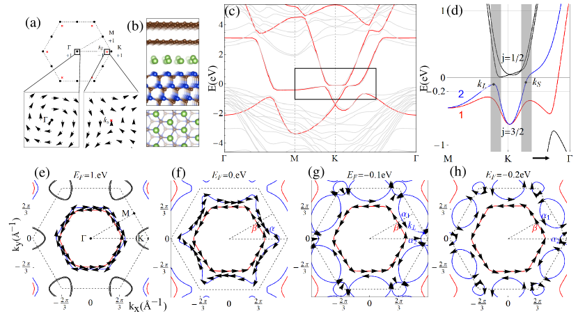
Lifshitz transition and momentum-space spin antivortex in monolayer Pb We start from the ground state lattice structure and electronic structure of monolayer Pb on top of SiC substrate. The Pb atoms form a triangular lattice described by the symmetry group that can be generated by a threefold rotation and an in-plane mirror. Inversion symmetry is broken due to the local environment, as shown in Fig. 1(b). The electronic structure of this system at the DFT level (see Supplemental Material SM Sec. I.B for details) without and with SOC are, respectively, shown in Fig. 1 (c) and 1(d). Focusing on the to eV energy range near the Fermi energy, the two strongly dispersive bands are mainly characterized by Pb and orbitals; the other weakly dispersive band anticrossing with the and bands is of orbital character from both Pb and the topmost Si layer of the SiC substrate. Band interpolation using maximally localized Wannier functions was then performed using the above four orbitals for initial projections (details in Supplemental Material SM ). The resulting Wannier-interpolated bands in Fig. 1(c) agrees well with the original DFT ones within the manifold of the four orbitals. After introducing atomic SOC to the tight binding Hamiltonian obtained from Wannierization, we obtain low-energy bands shown in Fig. 1(d). Labeling bands with SOC by total angular momenta at K, the bands are mainly dominated by Si orbitals and the bands [labeled as bands 1 and 2 in Fig. 1(d)] come from Pb orbitals; these two bands anticross around for eV.
We next show the evolution of Fermi surfaces across a Lifshitz transition in Fig. 1(e-h), where is lowered from eV to and eV. At eV, the spin-split hole pockets (blue) and (red) and the spin-split electron pockets around K (black) come from Pb orbitals. As the Fermi energy lowers to eV, the electron pockets shrink and disappear, while the hole pockets extend towards the Brillouin Zone (BZ) boundary. As the Fermi energy decreases further, the hole pocket are split into the electron pockets and around the M and K points, as shown in Fig. 1(h). A Lifshitz transition that changes the Fermi surface topology occurs at the momentum along the KM line at eV, as shown in Fig. 1(g).
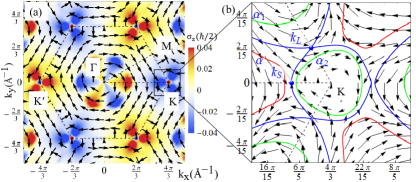
Also evolving with lowering Fermi energies along Fig. 1(eh) are spin textures of the Fermi pockets. At eV, the spin textures of two hole pockets are of Rashba-type. As the Fermi energy lowers, the spin texture of the inner hole pocket (red) remains the same while dramatic changes occur for the outer hole pocket (blue) that experiences the Lifshitz transition. By comparing the spin direction of the blue Fermi pocket at and eV, one notices that the spin direction of the Fermi pocket around at eV follows that at eV, while the spin direction of the Fermi pocket around K at eV reverses its sign, as compared to that at eV. To see this feature more clearly, we focus on the spin texture of band 2 in the whole BZ, as shown in Fig. 2(a), in which the arrows show the in-plane spin directions and the colors indicate the -component spin. It is clear that the in-plane spin forms vortices around , , , and . Zooming in on the spin texture of band 2 around K in Fig. 2(b), we find that, besides the vortex around K, another antivortex centered at appears along the line. The lines , and in Fig. 2(b) show the Fermi surfaces at eV and eV, respectively, and we indeed see a sign change of the spin direction for the momenta at the left and right sides of along the K line between these two Fermi surfaces, consistent with the Fermi pocket plot in Fig. 1(f) and 1(h).
The existence of the spin antivortex can be viewed as a consequence of the Poincaré-Hopf theorem of a tangential vector field on a compact manifold Fulton (2013). The BZ is a torus and we only focus on the in-plane spin component, which can be regarded as a tangential field. According to the Poincaré-Hopf theorem, the total of winding numbers around spin vortex is the Euler number of the torus, namely zero. The winding numbers of spin vortices at six high symmetry momenta, namely , , and three points, are all , as shown in Fig. 2(a). On the other hand, there are six antivortices due to the combination of and symmetries, each with winding number , as shown in Fig. 1(a). Thus, the total winding number in the whole BZ vanishes, as required by the Poincaré-Hopf theorem. This analysis suggests that, unlike a spin vortex around high symmetry momenta, each spin antivortex is movable along the lines, but is locally stable due to its topological nature. The difference between spin antivortex and other spin texture, such as spin vortex in the Rashba model, is further discussed in Sec.II.C of Supplemental MaterialSM . In addition, it is shown that the location of spin antivortex can be controlled by an external gate voltage, as discussed in Sec.II.B of Supplemental MaterialSM .
It is interesting to notice that both the Lifshitz transition and the spin antivortex occur approximately around eV, as shown in Fig. 2(b). This is because both phenomena are related to the anticrossings between the bands from orbitals and the bands from orbitals around or , as shown by the gray regime in Fig. 1(d). We provide more detailed analysis on how the band anticrossing can induce the Lifshitz transition and spin antivortex in Supplemental MaterialSM Sec.II.B.
Current-induced spin polarization and spin Hall effect The Lifshitz transition and spin antivortex can be experimentally verified by their spectroscopic signatures: they can, in principle, be extracted through the spin-resolved angular-resolved photoemission spectroscopy Sobota et al. (2021). Here we focus on the spin transport phenomena of CISP and SHE, which are described by the response equations, for CISP and for SHE, respectively. Here is the spin operator with , is the velocity operator with and is the spin current operator. Based on the threefold rotation and in-plane mirror symmetries , the nonzero in-plane current response coefficients for -direction electrical field are for CISP and for SHE from the Neumann’s principles Neumann and Meyer (1885).
The detailed form of the response coefficients and can be derived from the standard linear response theory and are given by
| (1) |
and
| (2) |
where and are the retarded and advanced Green’s functions, is the trace taken over band indices, and the vertex operator is defined as with the current operator and
| (3) |
Here, describes the vertex correction to the current operator from the ladder diagram of disorder scattering with the disorder density and scattering strength Mahan (2013). We apply the linear response formalism to the above-mentioned tight-binding model parametrized using Wannier functions; details of the numerical technique are discussed in Supplemental MaterialSM Sec. I.
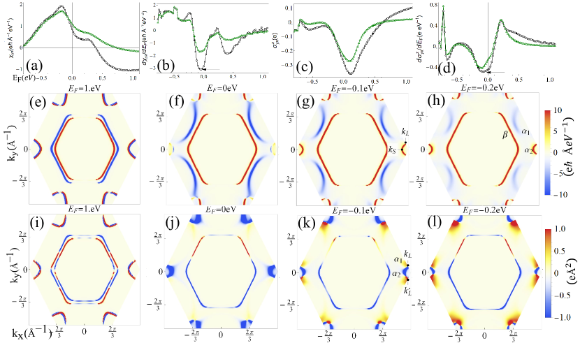
Fig. 3 summarizes our main numerical results for for CISP and for SHE, respectively. Here the green line is for the case without the vertex correction, namely , and the black line with vertex correction. We first analyze and plot its momentum resolved contribution of Eq. (1) in Fig. 3(e)3(i). We find that the main contribution to CISP comes from the Fermi surface since in (1) can be approximated by in the dilute disorder limit. At eV, due to the opposite spin texture for the two hole pockets, they contribute oppositely to CISP, as shown in Fig. 3(e). The outer Fermi pocket will be dominant and thus gives rise to the negative sign of , resembling the CISP contribution in the standard Rashba model Inoue et al. (2003). Near the Lifshitz transition, a dramatic change occurs to the outer Fermi pocket around and . When lowering the Fermi energy from to eV, one can clearly see that the Fermi pocket around and varies from blue (negative) to red (positive), as shown in Fig. 3(f) and 3(g). Physically, this sign change directly reflects the presence of spin antivortices, as the spin direction on the Fermi pocket around and changes its sign across the spin antivortex. In addition, the contribution to CISP from the Fermi pocket around M also decreases due to the reduction of relaxation time (See Sec. II.C of Supplemental MaterialSM ). Combining the above factors leads to (i) the positive sign of in this Fermi energy range ( eV) and (ii) a rapid increase of around eV as decreases. To see this rapid change more clearly, we take a derivative of with respect to , as shown in Fig. 3(b). The peak in the amplitude of indeed occurs around eV, as shown by the arrow in Fig. 3(b), and thus is induced by the Fermi surface crossing the antivortex. The SHE also reveals a rapid change around eV, as shown by a similar peak appears for in Fig. 3(d). This is because the contribution to SHE around the Fermi pockets close to the Lifshitz transition point and that around close to abruptly changes sign from negative (blue) to positive (red) when lowering the Fermi energy from to eV, as shown in Fig. 3(j) and 3(k). Detailed analysis suggests that the sign change of contribution around and is more closely related to the Lifshitz transition due to the fact that the SHE mainly is contributed from interband matrix elements rather than the intraband Fermi surface contribution, as discussed in Sec. II.D of Supplemental MaterialSM . The influence of disorder scattering is also evaluated through the vertex correction, as shown by the dashed lines in Fig. 3(a), 3(b) and 3(c), 3(d). We generally find both the values of and , as well as and , around eV are enhanced by disorder scattering, as discussed in details in Sec.II.C and II.D of Supplemental MaterialSM .
Conclusion and discussion In conclusion, the spin antivortices and Lifshitz transition induced by the anticrossing between the and bands strongly affect spin transport phenomena in the monolayer Pb on SiC. By choosing appropriate parameters (see Sec.II.E of Supplemental MaterialSM ), we find is of the order in our model and the corresponding spin Hall angle is , comparable to the existing experimentally measured values Morota et al. (2011); Mosendz et al. (2010); Ando and Saitoh (2010). Based on the same values, we find the variation of across the band anticrossing regime is around , and thus should be measurable by tuning the carrier density of 2D Pb in experiments. For CISP, is of the order and its variation is in the band anticrossing regime. The charge-to-spin conversion efficiency is , where is the Fermi velocity and is the longitudinal conductivity. This efficiency is close to that proposed and measured of graphene on a transition-metal dichalcogenide Ghiasi et al. (2019); Offidani et al. (2017). While Pb films have been grown on top of SiC with different growth methods Yurtsever et al. (2016); Chen et al. (2020); Wang et al. (2021); Hupalo et al. (2011); Liu et al. (2015), our theory suggests the monolayer Pb as an excellent platform for the study of spin transport phenomena and spintronic applications.
Acknowledgments–. We thank V. Crespi, J. Robinson, N. Samarth, W. Yanez and J. Zhu for helpful discussions. This work is mainly supported by the Penn State MRSECCenter for Nanoscale Science via NSF Grant No. DMR-2011839. C.-X. L. also acknowledges the support of the Office of Naval Research (Grant No. N00014-18-1-2793).
References
- Edelstein (1990) V. M. Edelstein, Solid State Communications 73, 233 (1990).
- Kato et al. (2004) Y. Kato, R. Myers, A. Gossard, and D. Awschalom, Physical Review Letters 93, 176601 (2004).
- Silov et al. (2004) A. Y. Silov, P. Blajnov, J. Wolter, R. Hey, K. Ploog, and N. Averkiev, Applied physics letters 85, 5929 (2004).
- Sih et al. (2005) V. Sih, R. Myers, Y. Kato, W. Lau, A. Gossard, and D. Awschalom, Nature Physics 1, 31 (2005).
- Zhang et al. (2015) H. Zhang, S. Yamamoto, B. Gu, H. Li, M. Maekawa, Y. Fukaya, and A. Kawasuso, Physical review letters 114, 166602 (2015).
- Li et al. (2016) C. H. Li, O. M. van‘t Erve, S. Rajput, L. Li, and B. T. Jonker, Nature communications 7, 1 (2016).
- Žutić et al. (2004) I. Žutić, J. Fabian, and S. D. Sarma, Reviews of modern physics 76, 323 (2004).
- Hirsch (1999) J. Hirsch, Physical review letters 83, 1834 (1999).
- Sinova et al. (2004) J. Sinova, D. Culcer, Q. Niu, N. Sinitsyn, T. Jungwirth, and A. H. MacDonald, Physical review letters 92, 126603 (2004).
- Murakami et al. (2003) S. Murakami, N. Nagaosa, and S.-C. Zhang, Science 301, 1348 (2003).
- Inoue et al. (2003) J.-i. Inoue, G. E. Bauer, and L. W. Molenkamp, Physical Review B 67, 033104 (2003).
- Trushin and Schliemann (2007) M. Trushin and J. Schliemann, Physical Review B 75, 155323 (2007).
- Johansson et al. (2016) A. Johansson, J. Henk, and I. Mertig, Physical Review B 93, 195440 (2016).
- Inoue et al. (2004) J.-i. Inoue, G. E. Bauer, and L. W. Molenkamp, Physical Review B 70, 041303 (2004).
- Briggs et al. (2020) N. Briggs, B. Bersch, Y. Wang, J. Jiang, R. J. Koch, N. Nayir, K. Wang, M. Kolmer, W. Ko, A. D. L. F. Duran, et al., Nature materials 19, 637 (2020).
- Steves et al. (2020) M. A. Steves, Y. Wang, N. Briggs, T. Zhao, H. El-Sherif, B. M. Bersch, S. Subramanian, C. Dong, T. Bowen, A. D. L. Fuente Duran, et al., Nano letters 20, 8312 (2020).
- Miró et al. (2014) P. Miró, M. Audiffred, and T. Heine, Chemical Society Reviews 43, 6537 (2014).
- Avsar et al. (2020) A. Avsar, H. Ochoa, F. Guinea, B. Özyilmaz, B. Van Wees, and I. J. Vera-Marun, Reviews of Modern Physics 92, 021003 (2020).
- Das et al. (2015) S. Das, J. A. Robinson, M. Dubey, H. Terrones, and M. Terrones, Annual Review of Materials Research 45, 1 (2015).
- Guo et al. (2005) G. Guo, Y. Yao, and Q. Niu, Physical review letters 94, 226601 (2005).
- Guo et al. (2008) G.-Y. Guo, S. Murakami, T.-W. Chen, and N. Nagaosa, Physical review letters 100, 096401 (2008).
- Freimuth et al. (2010) F. Freimuth, S. Blügel, and Y. Mokrousov, Physical review letters 105, 246602 (2010).
- Lowitzer et al. (2011) S. Lowitzer, M. Gradhand, D. Ködderitzsch, D. V. Fedorov, I. Mertig, and H. Ebert, Physical review letters 106, 056601 (2011).
- Gradhand et al. (2010a) M. Gradhand, D. V. Fedorov, P. Zahn, and I. Mertig, Physical review letters 104, 186403 (2010a).
- Gradhand et al. (2010b) M. Gradhand, D. V. Fedorov, P. Zahn, and I. Mertig, Physical Review B 81, 245109 (2010b).
- Fulton (2013) W. Fulton, Algebraic topology: a first course, vol. 153 (Springer Science & Business Media, 2013).
- Sobota et al. (2021) J. A. Sobota, Y. He, and Z.-X. Shen, Reviews of Modern Physics 93, 025006 (2021).
- Neumann and Meyer (1885) F. E. Neumann and O. E. Meyer, Vorlesungen über die Theorie der Elasticität der festen Körper und des Lichtäthers, gehalten an der Universität Königsberg (B.G. Teubner, 1885).
- Mahan (2013) G. D. Mahan, Many-particle physics (Springer Science & Business Media, 2013).
- Morota et al. (2011) M. Morota, Y. Niimi, K. Ohnishi, D. Wei, T. Tanaka, H. Kontani, T. Kimura, and Y. Otani, Physical Review B 83, 174405 (2011).
- Mosendz et al. (2010) O. Mosendz, V. Vlaminck, J. Pearson, F. Fradin, G. Bauer, S. Bader, and A. Hoffmann, Physical Review B 82, 214403 (2010).
- Ando and Saitoh (2010) K. Ando and E. Saitoh, Journal of Applied Physics 108, 113925 (2010).
- Ghiasi et al. (2019) T. S. Ghiasi, A. A. Kaverzin, P. J. Blah, and B. J. van Wees, Nano letters 19, 5959 (2019).
- Offidani et al. (2017) M. Offidani, M. Milletarì, R. Raimondi, and A. Ferreira, Physical review letters 119, 196801 (2017).
- Yurtsever et al. (2016) A. Yurtsever, J. Onoda, T. Iimori, K. Niki, T. Miyamachi, M. Abe, S. Mizuno, S. Tanaka, F. Komori, and Y. Sugimoto, Small 12, 3956 (2016).
- Chen et al. (2020) S. Chen, P. A. Thiel, E. Conrad, and M. C. Tringides, Physical Review Materials 4, 124005 (2020).
- Wang et al. (2021) J. Wang, M. Kim, L. Chen, K.-M. Ho, M. Tringides, C.-Z. Wang, and S. Wang, Physical Review B 103, 085403 (2021).
- Hupalo et al. (2011) M. Hupalo, X. Liu, C.-Z. Wang, W.-C. Lu, Y.-X. Yao, K.-M. Ho, and M. C. Tringides, Advanced Materials 23, 2082 (2011).
- Liu et al. (2015) X. Liu, T. Hu, Y. Miao, D. Ma, P. K. Chu, F. Ma, and K. Xu, Journal of Applied Physics 117, 065304 (2015).
- (40) See Supplemental Material for construction of the tight binding model from DFT and detailed numerical calculation of spin transport response functions for Rashba 2DEG and 2D Pb, which includes Refs. [41-53].
- Perdew et al. (1996) J. P. Perdew, K. Burke, and M. Ernzerhof, Phys. Rev. Lett. 77, 3865 (1996).
- Perdew et al. (1997) J. P. Perdew, K. Burke, and M. Ernzerhof, Phys. Rev. Lett. 78, 1396 (1997).
- Blöchl (1994) P. E. Blöchl, Phys. Rev. B 50, 17953 (1994).
- Kresse and Joubert (1999) G. Kresse and D. Joubert, Phys. Rev. B 59, 1758 (1999), eprint 0927-0256(96)00008.
- Kresse and Furthmüller (1996) G. Kresse and J. Furthmüller, Phys. Rev. B 54, 11169 (1996).
- Grimme et al. (2010) S. Grimme, J. Antony, S. Ehrlich, and H. Krieg, J. Chem. Phys. 132, 154104 (2010).
- Giannozzi et al. (2009) P. Giannozzi, S. Baroni, N. Bonini, M. Calandra, R. Car, C. Cavazzoni, D. Ceresoli, G. L. Chiarotti, M. Cococcioni, I. Dabo, et al., J. Phys. Condens. Matter 21, 395502 (2009), eprint 0906.2569.
- Marzari and Vanderbilt (1997) N. Marzari and D. Vanderbilt, Phys. Rev. B 56, 12847 (1997).
- Mostofi et al. (2008) A. A. Mostofi, J. R. Yates, Y.-S. Lee, I. Souza, D. Vanderbilt, and N. Marzari, Comput. Phys. Commun. 178, 685 (2008).
- Souza et al. (2001) I. Souza, N. Marzari, and D. Vanderbilt, Phys. Rev. B 65, 035109 (2001).
- Wei et al. (2021) Y.-W. Wei, C.-K. Li, Y. Cao, and J. Feng, Computer Physics Communications 258, 107551 (2021).
- Barata and Hussein (2012) J. C. A. Barata and M. S. Hussein, Brazilian Journal of Physics 42, 146 (2012).
- Sinova et al. (2015) J. Sinova, S. O. Valenzuela, J. Wunderlich, C. Back, and T. Jungwirth, Reviews of Modern Physics 87, 1213 (2015).