Characterizing and Improving the Resilience of Accelerators in Autonomous Robots
Abstract
Motion planning is a computationally intensive and well-studied problem in autonomous robots. However, motion planning hardware accelerators (MPA) must be soft-error resilient for deployment in safety-critical applications, and blanket application of traditional mitigation techniques is ill-suited due to cost, power, and performance overheads. We propose Collision Exposure Factor (CEF), a novel metric to assess the failure vulnerability of circuits processing spatial relationships, including motion planning. CEF is based on the insight that the safety violation probability increases with the surface area of the physical space exposed by a bit-flip. We evaluate CEF on four MPAs. We demonstrate empirically that CEF is correlated with safety violation probability, and that CEF-aware selective error mitigation provides , , and lower Failures-In-Time (FIT) rate on average for the same amount of protected memory compared to uniform, bit-position, and access-frequency-aware selection of critical data. Furthermore, we show how to employ CEF to enable fault characterization using fewer fault injection (FI) experiments than exhaustive FI, and evaluate our FI approach on different robots and MPAs. We demonstrate that CEF-aware FI can provide insights on vulnerable bits in an MPA while taking the same amount of time as uniform statistical FI. Finally, we use the CEF to formulate guidelines for designing soft-error resilient MPAs.
Index Terms:
Reliability, Autonomous robots, Motion planning, Collision detection.1 Introduction
Autonomous robots are increasingly used for real-time and safety-critical tasks, including medical care [35, 22], autonomous driving [103, 105], and home assistance [113, 57]. The rate of autonomous robot deployment is expected to reach 2.2 million units per year by 2022 [49, 28, 48]. As autonomous robots are becoming an integral part of our lives, it is crucial to ensure that an autonomous robot does not collide with other objects, and thereby harm the safety of its surroundings.
Motion planning allows an autonomous robot to navigate and reach its end goal safely without collisions. Therefore, motion planning is key to the many tasks performed by autonomous robots, including navigation, object manipulation, footstep planning, and full-body movement. It has been an area of study since the 1970s [60, 56], and is today one of the key research topics in robotics. For example, motion planning constitutes about of the total publications in top robotics conferences [1, 3] (ICRA-2020 had 1073 papers, 121 of which were in motion planning). Motion planning has also received significant attention from industry, with an increasing number of patents. For example, the number of patents granted every year by the United States Patent Office (USPTO) on collision detection and motion planning has increased by from 2015 to 2020 [107, 32].
The computational and real-time demands of motion planning exceed those provided by typical CPUs. Recently, several approaches have been proposed to accelerate motion planning on different hardware platforms, including GPUs [10, 29], FPGAs [6, 78, 93], and ASICs [76, 95, 66, 116]. Motion Planning Accelerators (MPAs) have achieved impressive performance gains and are being adopted in industry [84, 46, 89].
However, the use of MPAs in robotics applications has significant safety implications. For example, the IEC 61508 [47] provides functional safety standards for electronic systems used in applications such as robotics in terms of allowable FIT (Section 2.3), where 1 FIT is one failure per billion hours. In modern systems, errors induced by particle strikes and radiation, or soft errors, make up the majority of SRAM and register-level faults [71, 97]. Hence, soft errors are a major threat to FIT level compliance in MPAs used in robotics applications. Furthermore, due to their transient nature, soft errors cannot be eliminated during the design and test phases of a chip, and hence need runtime mitigation.
There have been many studies on the effects of soft errors on CPUs and GPUs [75, 104, 65, 108, 41, 110, 25], deep learning accelerators [64, 83], and autonomous vehicle systems [9, 52, 53]. However, their impact on accelerators for robotics has not been studied. Application-agnostic blanket error mitigation techniques such as error-correcting codes (ECC) and dual/triple modular redundancy (DMR/TMR) can increase the area, cost, and power by - (Table IV), and degrade the performance of these hardware accelerators. With consumer applications driving growth of robotics, the electronics controlling these systems will become increasingly cost-sensitive [31, 80, 19]. Furthermore, any increase in the MPA’s power consumption significantly reduces the operation time of a mobile robot with a single charge as MPAs suitable for real-time motion planning contribute to - of the total power consumption of robotic systems [106, 59, 115, 67]. While there has been work on sensor and actuator faults in autonomous robots [18], there has been no study of the reliability of MPAs in the presence of soft errors. To the best of our knowledge, we are the first paper on characterizing and improving the reliability of MPAs.
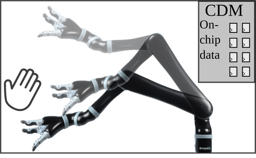
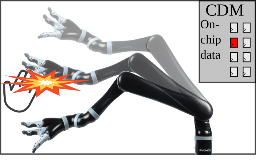
In this paper, we study soft errors in the collision detection module (CDM), which is the largest, most energy-consuming, and safety-critical component in MPAs [76, 95, 66, 6]. We find that CDMs in these accelerators consist of on-chip storage elements to store the information about space that the robot passes through for possible motions. These storage elements account for more than % of the sequential elements, and so we focus on it in this paper.
Figure 1 shows the effect of soft errors in the CDM. In the error-free scenario (Figure 1(a)), the robot navigates safely to the end goal. However, in Figure 1(b), a soft error causes the MPA to misidentify a path taken by the robot as safe, thereby resulting in a collision. This mis-identification is due to an error modifying the geometric representation of the space that the robot passes through.
Prior work has explored memory and register file designs that allow flexible partition into protected and non-protected regions for incorporating selective error mitigation in systems using CPUs and GPUs [118, 13, 73, 112, 117]. These techniques protect only the most vulnerable data and do so by placing it in protected memory. A challenge with applying such an approach to error mitigation is that it requires accurate and fast identification of the most critical data. One approach is to use exhaustive fault injection (FI) to identify storage bits that exhibit the highest resilience improvement when protected from soft errors. Unfortunately, exhaustive FI can take up to CPU hours for a typical MPA (Section 6.1.1). Such high FI time overhead for error mitigation each time the MPA is reconfigured for a different task or robot introduces practical deployment challenges. For fully autonomous robots, the MPA’s storage data can be generated or modified at runtime [51, 44, 27], requiring runtime characterization of vulnerable data for selective error mitigation. Also, as noted in earlier work [75] exhaustive FI is an inefficient way to gain insight during architecture design.
Prior work on FI techniques for CPUs and GPUs [104, 65, 41, 110, 25, 79] has obtained significant reductions in the FI time. These FI tools and techniques are targeted towards specific languages, Instruction Set Architectures (ISA), or CPU/GPU system simulators and often exploit the microarchitecture or ISA to reduce the FI time and estimate the failure probability (Section 8). However, these techniques cannot be directly applied to robotic accelerators that use specialized microarchitectures and instruction sets. Thus, there is a need for techniques that efficiently characterize the effect of soft errors in robotics applications.
Architectural Vulnerability Factor (AVF) has been widely used to define the vulnerability of a system and can be measured using an analytical method such as Architecturally Correct Execution (ACE) analysis [75] or FI [63]. Directly applying AVF methodology such as ACE analysis to MPAs requires considering the positions of obstacles in the environment, thus leading to the need to run a large number of simulations to accurately estimate the fraction of time a hardware storage element contains an ACE bit.
To overcome these challenges, we introduce a novel heuristic, Collision Exposure Factor (CEF) that depends only upon the accelerator and robot, not on the environment. Other heuristics, such as bit position [64] and access-frequency [58, 70] have been proposed to find critical bits for deep learning accelerators and embedded applications, respectively. However, our analysis shows that considerable variation exists in the failure probabilities of bits with the same access-frequency or bit position in MPAs. In contrast, our approach provides a higher reduction in the overall failure probability as our proposed heuristic is more accurate at finding critical bits in the MPAs (Section 6.2).
The CEF estimates the architectural vulnerability factor of memory locations storing spatial information. The 3D model data of the swept spaces of a robot’s possible motions play a key role in real-time collision detection and motion planning. The main reason for safety violations due to a soft error is a modification of this stored 3D model of the swept space, which potentially leads to erroneous collision detection (Figure 1). To account for this violation, we define the CEF as the surface area of the swept space of the robot exposed to obstacles by a soft error.
By considering the entire swept space of the robot’s motion, the CEF decouples the effects of the robot model and the environment on safety violations. CEF can be calculated once for a given MPA and robot without needing to consider obstacles in the environment (which might be highly dynamic). The underlying reason this separation is possible is that, in the most widely used approaches for real-time motion planning, a robot has a fixed set of possible short motions that are precomputed independently of obstacle positions [62]. During operation a subset of these motions is selected to navigate to a given goal depending upon obstacle positions. For purposes of fault analysis we decouple these steps by assuming a conservative distribution (e.g., uniform) on where objects will appear. We show empirically that the CEF computed this way independent of the actual environment is positively correlated with the average failure probability due to a soft error.
Further, we propose a CEF-aware error mitigation technique to selectively protect values with higher CEF in an MPA’s on-chip storage. Finally, we propose a two-phase FI methodology: Phase 1 FI to find the CEF of all the bits (for a given robot and MPA), and Phase 2 FI to find the relation between the CEF and failure probability with fault site pruning. Uniform statistical FI-based characterization of the CDM provides similar speedup over exhaustive FI as CEF-aware FI (Section 6.1.1). However, it does not find the safety-violation probability of an individual bit nor does it find relative vulnerability of different bits, which is needed for error mitigation. In CEF-aware FI, on the other hand, decoupling the two FI phases allows efficient calculation of the CEF and safety-violation probability for every bit in the CDM.
In summary, we make the following contributions in this paper:
-
•
Establish the necessary conditions for safety violations (i.e., collisions), and propose Collision Exposure Factor (CEF), a reliability metric for CDM storage elements.
-
•
Propose an efficient CEF-aware error mitigation technique that selectively protects values with higher CEF, and compare it to uniform, exhaustive FI, bit position-aware, and access-frequency-aware application of DMR, TMR, and ECC techniques for four different CDM designs.
-
•
Propose a two-phase FI methodology using the CEF of storage elements for fault site pruning to reduce FI time by orders of magnitude.
Our results show that CEF-aware selective error mitigation results in , , and lower FIT rate for the same amount of protected memory compared to uniform, bit position, and access-frequency-aware selection of critical data. Further, CEF-aware FI reduces the FI time by with minimal loss of accuracy, and finds the FIT rate of the MPA and individual bits. Finally, we study the impact of architectural design parameters on resilience and error mitigation overheads, and demonstrate the potential for developing efficient soft error resilient MPA architectures using the CEF metric.
2 Background and Motivation
This section briefly summarizes relevant background information on motion planning, general CDM architecture, and safety in robotics. Finally, we summarize the limitations of current FI methodologies, and discuss the need for application-specific reliability metric and FI methodology for MPAs.
2.1 Motion Planning
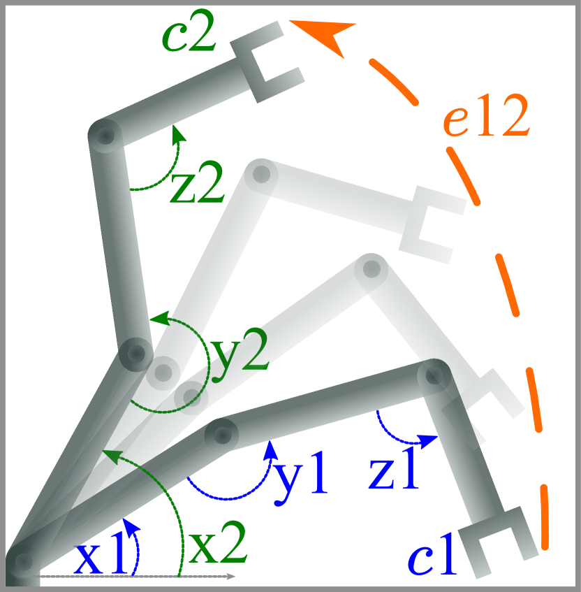
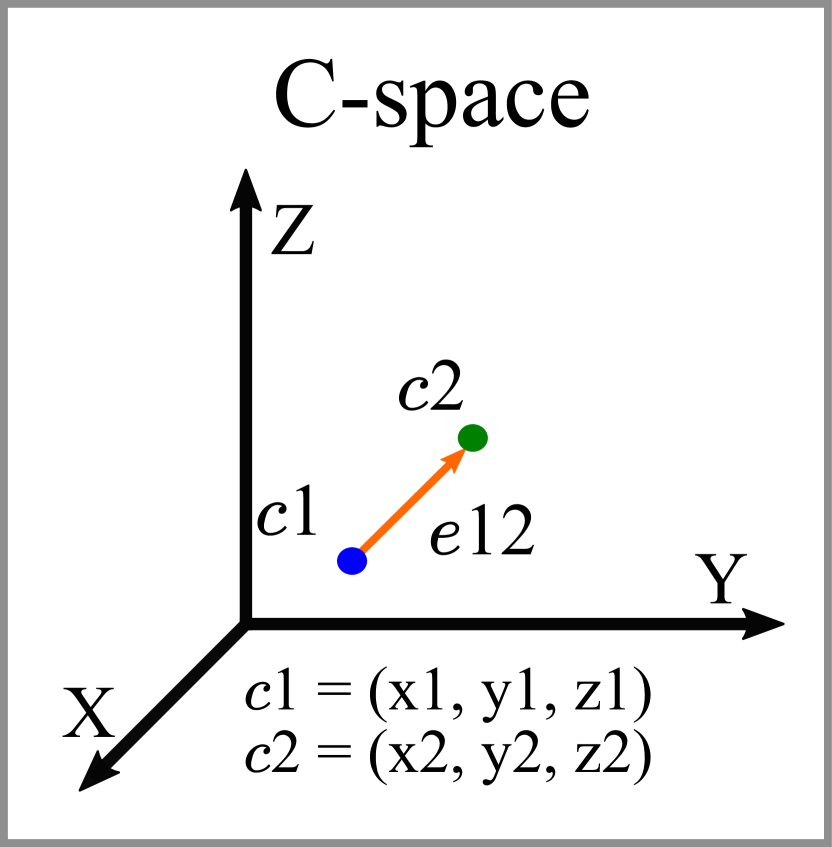
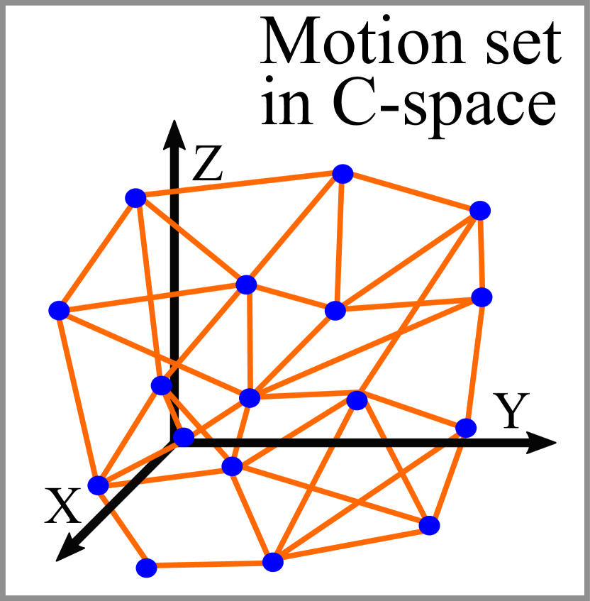
The objective of motion planning is to compute a collision-free path for a robot. Motion planning is performed in the robot’s configuration space (C-space), which has the same number of dimensions as the robot’s degrees of freedom (DOFs). Figure 2(a) shows a planar robot with three DOFs, while Figure 2(b) represents its C-space. Each dimension of the C-space represents the range of angles of a joint of the robot. The point with coordinates (x1, y1, z1) in the C-space corresponds to the pose in Figure 2(a). Similarly, edge represents the robot’s motion from to .
The complexity of motion planning increases exponentially with the robot’s DOFs [90]. Thus, approximate methods such as probabilistic roadmaps [55] are widely used [61, 90] over the last 20 years. Many hardware accelerators [6, 93, 76, 77, 66, 116] have been proposed for these algorithms.
2.1.1 Probabilistic roadmaps

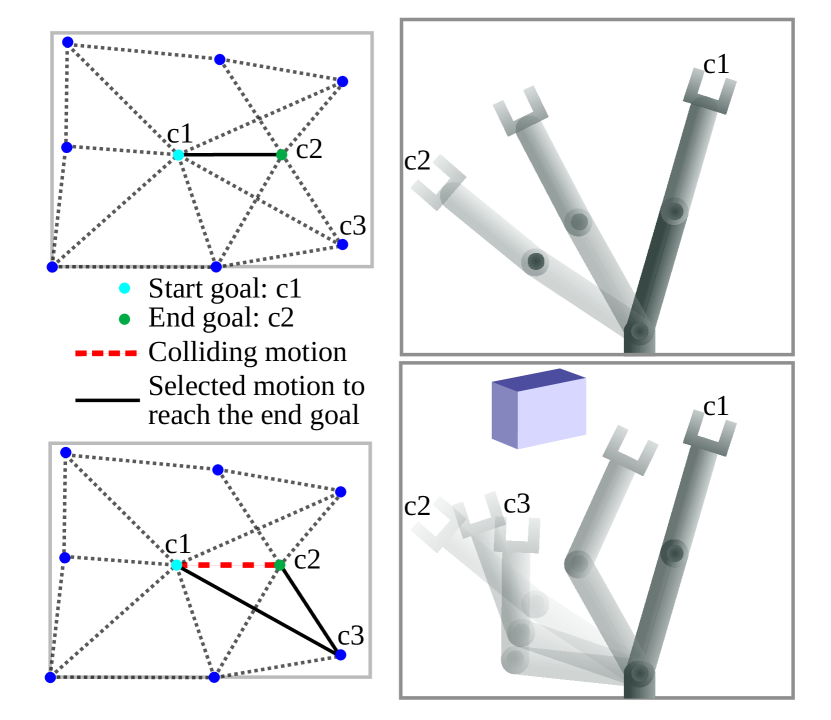
Probabilistic motion planning consists of two phases. In the preprocessing stage, a graph, called a motion set, is constructed in the robot’s C-space. Figure 2(c) and Figure 3(a) give examples of motion sets for a robot with three and two DOFs, respectively. The nodes in the graph correspond to the robot’s spatial poses, and an edge between close-by nodes represent motion generated by a local planner (e.g., linear interpolation between two poses) from one pose to another. Motion set consists of collision-free poses and motions of the robot for a given environmental scenario. In the query phase, a path search algorithm (e.g., Dijkstra’s algorithm) is used to find a path between given start and end poses using the precomputed motion set. A path consists of one or more motions from the motion set. The probabilistic roadmap is a multi-query method, i.e., the same motion set is used to perform motion planning for multiple combinations of start and goal poses.
Leven and Hutchinson [62] proposed a real-time motion planning approach based on probabilistic roadmaps for a dynamic environment and is also used by MPAs [93, 76, 77, 66, 116, 39]. In this approach, the motion set is generated for an obstacle-free environment. At runtime, collision detection is performed to find collision-free motions in this set for a given placement of obstacles. The path search module considers collision-free motions to find a feasible path between the start and end pose in the resulting collision-free motion set graph. For example, in Figure 3(b) (bottom), an obstacle in the robot’s environment makes some of the motions in the motion set flagged as “colliding motion”, which are avoided by the path search module to find a path between c1 and c2.
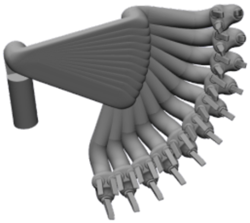
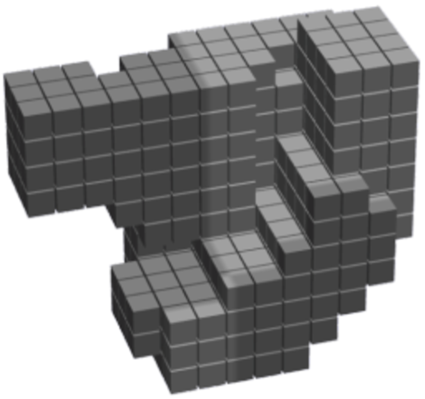
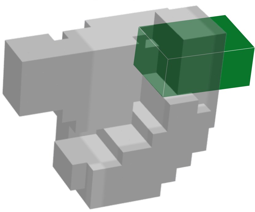
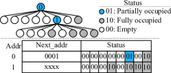
The information about the swept space of each motion in the motion set is stored in the memory to facilitate real-time collision detection. Swept space of a motion is the part of space occupied by a robot as the given motion is followed. For example, as shown in Figure 4(a) and Figure 4(b), a motion’s swept space is discretized, and its 3D model is stored. As shown in Figure 4(c), the motion’s swept space is checked for overlap with obstacles for collision detection at runtime. For fully autonomous robots, depending upon the environment, the motion set is modified [51, 44, 27] and swept spaces of new motions are generated at runtime. This update is performed outside of the critical path of motion planning.
The collision detection step is the most time- and energy-consuming in motion planning and takes up to 99% of the total runtime on a CPU [10]. As collision detection must be performed in real-time with low latency to ensure safety in an environment with dynamic obstacles, MPAs typically dedicate more than 85% of their total area to accelerate collision detection [76, 77, 66], making the CDM the most vulnerable component in an MPA. Unfortunately, an erroneous collision detection can potentially lead to a collision between the robot and an obstacle in its surroundings, making collision detection safety-critical. Thus, we focus on the CDM and perform fault characterization of CDMs of four MPAs, which we refer to as A1 [78], A2 [76], A3 [66], and A4 [116] (Section 5.2) throughout this paper.
2.2 Collision Detection Modules (CDM)
Many approaches have been proposed to accelerate collision detection on different hardware platforms. The architecture proposed by Murray et al. [78] uses specialized combinational circuits for a given motion set, but it is not reconfigurable to different motion sets at runtime. In contrast, GPU-based collision detection acceleration [10, 29] provides high flexibility, but it is not energy-efficient. Configurable collision detection hardware accelerators [6, 93, 76, 77, 66, 116] provide a balance between flexibility and performance/energy-efficiency. We focus on such configurable CDM architectures.
Figure 7 illustrates the architecture of a generic configurable CDM. The CDM consists of collision detection circuits (CDCs). It exploits inter-motion parallelism to check multiple motions for collision in parallel. Each CDC consists of on-chip memory to store a motion’s swept space, and exploits inter-query and intra-query data reuse. The on-chip storage can be configured for different motions at runtime. Based on our synthesis experiments, the on-chip memory to store swept spaces constitutes more than of the sequential elements in CDMs.
The key design consideration of CDMs is the geometric representation used to store swept spaces in the memory. Several representations for storing the 3D model have been proposed for motion planning, including polygonal meshes [5], bounding box hierarchies [109, 33], voxels [88], and octrees [50]. These approaches differ in storage requirements, representation accuracy, and computational complexity.
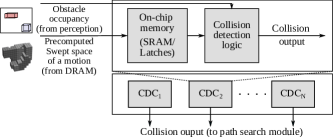

Note that the proposed metric CEF is applicable regardless of the geometric representation used. All CDM hardware accelerators use either grid-based (Figure 5(b), Figure 5(c)) or octree-based representations (Figure 7) (explained in Section 3.1) as these representations are less compute- and memory-intensive. For both representations, the swept space of a motion is discretized into fixed-size cubes known as voxels. Voxelized swept space is then stored using a set of structures specific to the representation used. At runtime, a perception sensor module senses obstacles occupancy information, converts it to voxels, and sends it to the CDCs. The CDCs perform collision detection for stored motions and send the output to the path search module.
2.3 Functional Safety in Robotics
| No ECC | Full ECC | Selective ECC (SIL 2) | Selective ECC (SIL 3) | |
|---|---|---|---|---|
| Total area (mm2) | 450 | 502.5 | 454.5 | 469.8 |
| Cost/die ($) | 59.9 | 70.0 | 60.8 | 63.6 |
Safety is a crucial consideration in robotics. Hence, the failure rate of circuits used in robotics applications, including MPAs, is an important factor. The FIT rate of a circuit consisting of multiple components can be computed using Equation (1) [75, 64].
| (1) |
is the raw FIT rate defined in FIT/Mb units and depends upon multiple factors including technology node, ambient conditions, and elevation [87]. is the number (in Mb) of sequential elements/latches in component . is the probability that a fault in component affects the output of the application.
IEC 61508 [47] defines an international safety standard for safety-critical electronic systems. This standard is based on the risks of failure and defines four Safety Integrity Levels (SIL). Each SIL expresses the upper bound on the FIT rate. SIL 1 is the least stringent, while SIL 4 is the most stringent. The maximum allowable FIT rate decreases by three orders of magnitude from SIL 1 () to SIL 4 (). Note that the IEC 61508 standard considers the entire electronic system, not only the MPA.
One approach to make circuits soft error-resilient for certifiable safety is to use hardware error mitigation techniques on storage structures, which incurs high cost/power/performance overheads. Autonomous vehicles and robotics industries typically have shallow profit margins. For example, the profit margin per unit is under for several automobile industries [114]. Electronic systems contribute up to to the total cost of a car [82, 20] (at the time of writing). Hence cost-effective solutions to make MPAs more reliable are imperative [19]. The overheads for complete protection of storage structures from soft errors increase with their size. In such a case, the protection may be sacrificed entirely if the area/power overheads are not under budget. In comparison, selective protection is flexible and provides certifiable safety with less overhead than complete protection of storage structures by protecting only the most vulnerable data.
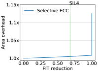
Table I compares the die area and cost for complete and selective ECC for the A3 [66]. As shown in Table II, selective ECC can reduce the cost by for SIL 3 ( increase in the profit margin). While the table compares only the die cost, an increase in the die area has a cumulative effect on the total cost of an electronic system, amplifying the need for selective error mitigation.
2.4 Fault Injection (FI)
In a circuit, a soft error can occur at any location and time. Assuming a single-bit error model, where only one bit is affected by a soft error in the component, exhaustive fault characterization typically requires A B FI runs. In this equation, A is the number of fault sites in space, and B is the number of fault sites in time. A is determined by the number of bits, and B is determined by the application’s total execution cycles and the number of possible inputs to the application. Unfortunately, this requires very high numbers of FI runs. In MPAs, different combinations of obstacle positions (input to collision detection) add to the number of FI runs, making the space even larger.
Accelerators’ fault characterization is typically carried out by statistical FI experiments [26, 41, 63, 15, 64, 40]. Statistical FI performs random sampling in the fault space and allows to tune the number of FI experiments as per the required confidence of the estimated FIT rate for a system [63]. Often, statistical FI is performed per component to find the safety-critical components in a circuit. However, the CDM component occupies more than of the area in an MPA and mainly consists of sizeable on-chip storage structures to store swept spaces. Hence, selective error mitigation of CDM requires a strategic approach to determine the safety-critical data in the on-chip storage. Further, the number of FI runs needed for statistical FI increases with a decrease in the probability of a bit error resulting in an output error, i.e., the failure probability of a component [63]. Typical CDMs have a low overall failure probability () which increases the number of FI runs required when using uniform random statistical FI (Section 6.1.1). Therefore, it would be beneficial to develop an application-aware FI strategy in which the sites for FI are strategically selected while keeping the number of FI runs required low.
3 Reliability Metric for Motion Planning
In this section we start by considering how erroneous collision-detection outcomes can lead to safety-critical events, then describe Collision Exposure Factor (CEF) in detail, and finally discuss how to apply CEF to building resilient MPAs.
Specialized accelerators, such as a CDM, obtain efficiency by replacing long sequences of software instructions with specialized hardware. Such accelerators may perform computations under the supervision of a command processor via an ISA interface (e.g., Google’s TPU [54]), and/or may start computation triggered by an event such as the arrival of a new frame of data in a buffer [17]. While an error originating in the accelerator could potentially propagate to the command processor and thereby result in erroneous operation (e.g., hang or system software crash) this paper focuses on Silent Data Corruption (SDC) within the CDM that can result in the robot colliding with an object in its environment.
Given a motion set and the current positions of obstacles collision detection finds motions that may lead to collisions. We define an SDC-C as an event involving a false-negative result when performing collision detection for a proposed motion and an object (i.e., a colliding motion is misidentified to be collision-free even though sensors detected an object the proposed motion would collide with if chosen during path search). Since, in general, an obstacle might appear anywhere in the environment, a naive (but expensive) approach to estimate SDC-C probability is to simulate many sample environments, each with randomly placed obstacles. Below we consider a more efficient approach suitable, for example, during CDM architecture design.
3.1 Collision Exposure Factor (CEF)
To analyze the errors that can occur in a CDM circuit and their effect on SDC-C probability, we focus on bit changes that can lead to false-negative collision detection. Specifically, we consider the impact of a change in a single bit used to represent a portion of a motion’s swept space. As mentioned in Section 2.2, swept spaces of the motions are stored in CDM memory and used to find possible collisions with the obstacles. Each bit in the on-chip storage helps specify the bounds of some motion’s swept space. We define the critical space of a bit as the region excluded from the swept space if that bit changes value due to a fault. This region represents a part of the swept space that can potentially lead to a false-negative collision detection. We then define the collision exposure factor (CEF) of a bit as the surface area of that bit’s critical space exposed to obstacles. If the geometric representation uses voxelized swept spaces, the CEF can be normalized to the surface area of one face of a voxel.
For a given erroneous bit, it is more likely that an obstacle occupies its critical space and results in an SDC-C as the exposed surface area of this critical space increases. Hence, intuitively, the SDC-C probability of a bit is proportional to its CEF value (Section 6.1.2). Note that the CEF of a bit is independent of the position of the obstacles in the environment. The CEF captures the probability of obstacles appearing in critical space and decouples the effect of a soft-error and exact position of obstacles on SDC-C probability. While the CEF definition assumes a uniform distribution of obstacles, it can also be extended to nonuniform distributions. For example, the CEF value can be scaled by the estimated probability of obstacles occupying the critical space for a nonuniform distribution of obstacles in the environment.
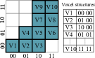
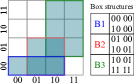
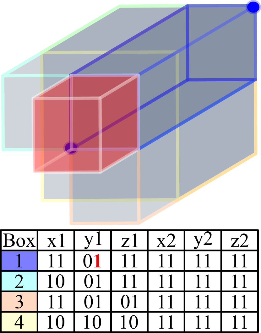
Figure 8 illustrates the critical space of specific bits due to single-bit errors for different geometric representations. Figure 8(a) reproduces Figure 6(a), and represents the swept space of a motion. Geometric representation methods convert the swept space to a set of structures, such as voxels (used in A1 described in Section 5.2), boxes (used in A2), or octree nodes (used in A3 and A4). Each of these structures is encoded into bits and stored in the on-chip storage of the CDM. For example, a voxel structure is stored using its coordinates, a box structure is stored using the coordinates of the diagonal voxels, and an octree node structure is stored using a custom data structure described below. A bit flip caused by a soft error would modify the space represented by the structure in different ways depending on the location of the bit in the structure and the geometric representation.
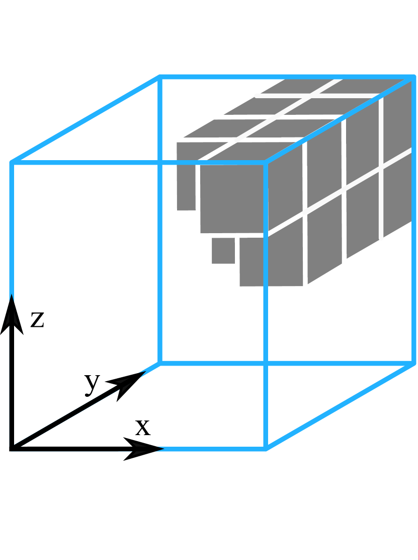
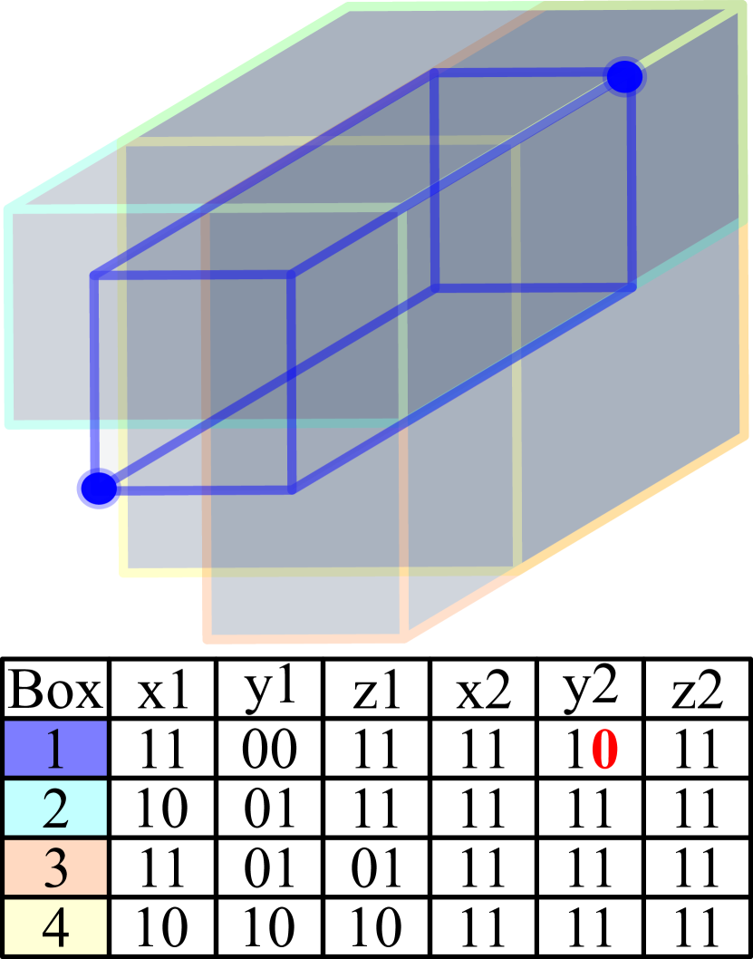
Figure 8(b) shows a box-based representation of the swept space, where four boxes are required to cover the swept space. Since space is divided into four voxels in , , and directions, a total of six () bits are used to store a coordinate. The highlighted box is represented with coordinates and of the diagonal voxels, before any error is introduced. In Figure 8(c), flipping a specific bit causes the value of to increase by one voxel. As the voxel highlighted in red is now excluded from the box, and no other box covers the voxel, it becomes part of the bit’s critical space. A soft error in this bit results in the exclusion of the critical space from swept space; hence the collision detection circuit fails to detect a collision if an obstacle occupies this critical space, leading to an SDC-C. In contrast, in Figure 8(d), a bit flip causes to decrease, but this bit flip is masked and does not impact the CDM’s output as other boxes cover the voxels exposed.
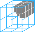
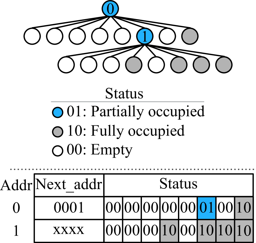
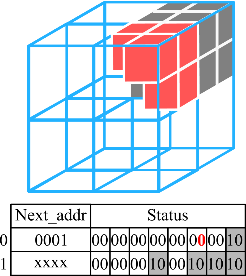
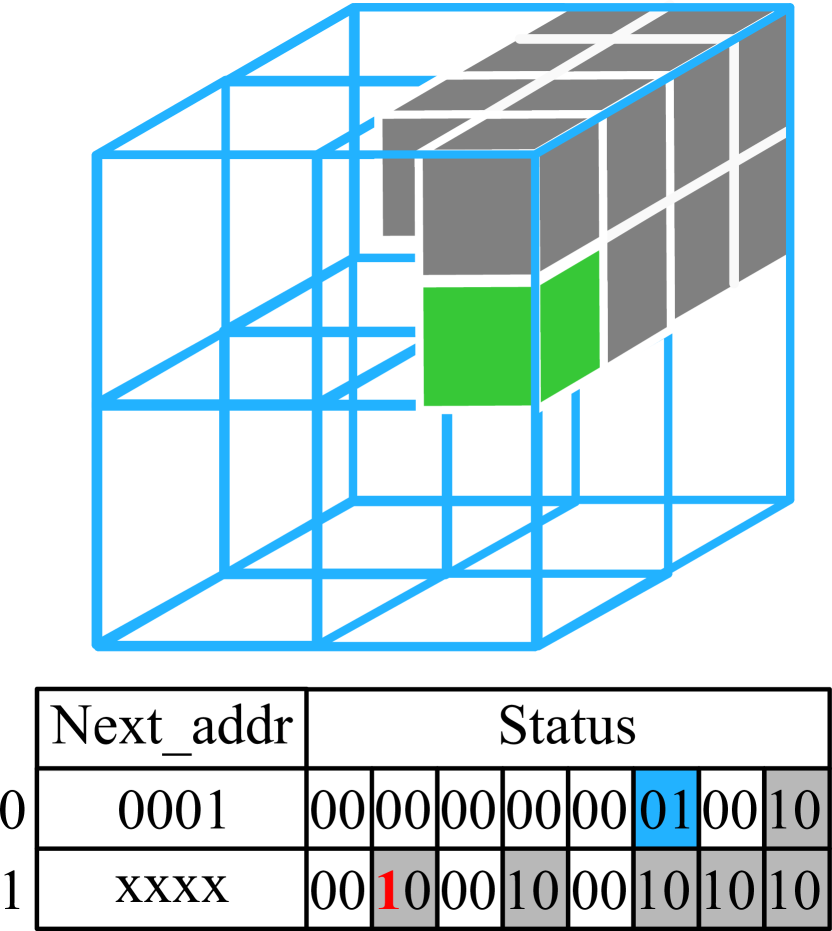
Figure 8(e) shows the octree representation of the same swept space. In this representation, the root node and all partially occupied nodes are stored in memory using a tree data structure. Each node in the tree contains two fields: “status” and “next_addr”. The status field contains an entry for each octant within the node indicating whether that octant is empty, partially or fully occupied. Only partially occupied octants are further divided. The next_addr field contains the start address of an array holding the resulting children nodes. For example, in Figure 8(e), the node stored in memory at address 0 contains only one partially occupied octant, and the node containing information about it is stored at address . In Figure 8(f), a bit flip in the node at address 0 modifies the status of a particular octant to be “fully empty”, thereby adding all the voxels in that octant to the critical space. In Figure 8(g), a bit flip in the node at address 1 modifies the status of an octant to “fully occupied”, resulting in a false-positive rather than a false-negative. In this case, motions that would not lead to a collision may be disallowed. However, this false-positive outcome does not result in potential for a collision (an SDC-C). Therefore, this voxel (highlighted in green) is not a part of the critical space.
Input: Motion_set, Swept_data, Swept_voxels, CDM;
Output: bit_info = {bitID: (CEF, Critical_space)};
For a given motion set of the robot and accelerator, the CEF of all the bits can be calculated using Algorithm 1. The algorithm works by considering each possible motion in turn (Line 1). For a given motion, Swept_data returns the storage bits used to represent its swept space (Line 2), and Swept_voxel returns the voxels in the swept space of that motion (Line 3). The loop between Line 4 and 14 considers each bit in the Swept_data. The CDM takes precomputed swept space (i.e., bits) and obstacle occupancy voxels as inputs and performs collision detection (Figure 7). The storage elements of the CDM are initialized with bits. To find the critical space an FI run is performed setting voxels as the obstacle occupancy voxels input to the CDM (Line 6). Specifically, a fault is injected into a low-level (e.g., RTL or microarchitectural simulator) model of the CDM at bit b (Line 6). The CDM outputs a Collision_vector containing collision detection output for each voxel in voxels. To find the critical space, each bit of the Collision_vector is checked (Lines 7-11). For an error-free run, the CDM detects collision for all the voxels in the swept space (i.e., voxels). However, for an FI run, a voxel v is added to the Critical_space if the CDM does not detect a collision (Line 8 and 9). CEF is then calculated by measuring the exposed surface area of the Critical_space (Line 12). Note that the CEF is obtained without the need to consider a potentially unbounded set of environments and object placements. Thus the number of FI runs to measure CEF using Algorithm 1 is orders of magnitude lower than exhaustive FI in which for each bit, multiple FI runs need to be performed with a large number of environment scenarios.
As presented above, Algorithm 1 assumes an RTL or architecture model for the CDM. We note that the resulting reliance upon fault injection to determine CEF could be avoided provided an analytical model is available to compute the critical space on Lines 5 to 12. Such a model could be used to analyze CEF prior to the development of RTL or architecture simulators.
Algorithm 1 is proposed for CDMs that use a voxelized representation of spatial data and output collision decisions (A1-A4). The majority of the collision detection acceleration approaches for robotics use voxelized representation as it consumes less memory and computational resources compared to polygonal mesh-based representation [23]. However, the concept behind CEF is applicable regardless of the underlying design parameters, and Algorithm 1 to measure the CEF needs can be modified for a different CDM. For example, for a triangle meshes-based representation of swept space, Line 5 to Line 12 can be replaced by a geometry-based calculation of the exposed surface area.
CEF is useful for CDMs that dedicate a significant area to storage structures for spatial data. Earlier work on FPGA-based accelerators [76] uses combinational logic to encode spatial data. Combinational logic is known to be less prone to soft errors compared to sequential elements [30]. However, the definition of CEF applies to erroneous combinational logic gates if needed.
3.2 CEF-aware Error Mitigation
For a fixed budget of area/power overhead, selective protection of the most vulnerable bits provides the optimal reduction in the FIT rate. Selective error mitigation in storage structures can be implemented by reliability-aware data placement to partially protected memory. However, this requires efficient ways to identify vulnerable data as the data can be generated/modified at runtime. We find that the CEF of a bit gives a measure of its impact on the SDC-C probability of the CDM (Section 6.1.2). Therefore, we can use information about the CEF of each bit in an input design to selectively apply error mitigation techniques such as ECC, DMR/TMR, and strike suppression. This reduces the cost of providing resilience compared to blanket protection of all the bits.
Selective mitigation is applied by CEF-aware data placement to the on-chip memory of the accelerator. Different structures such as voxel (A1), box (A2), and octree node (A3) are stored in the on-chip storage of the CDM depending upon the geometric representation method used. CEF-aware error mitigation is performed by placing structures with higher CEF in the protected storage regions. In our evaluation, the sum of CEFs over all the bits in a structure is used to sort the structures in descending order of CEF for selective error mitigation. Because CEF of a bit is proportional to the SDC-C probability, CEF-aware data placement results in a higher reduction of the overall FIT rate for a given fraction of protected storage compared to other heuristics (Section 6.2). The CEF measurement is done offline or outside of the critical path using Algorithm 1 after motion set generation.
Selective error mitigation can also be used to guide the accelerator design process. At the accelerator design stage, the designer can perform CEF-aware FI (Section 4.1) for a set of target robots, motion sets, and the expected number of obstacles in the environment to find the distribution of CEF, SDC-C probability of bits, and the FIT rate of the accelerator without any error mitigation. Based on this information, a designer can determine the required fraction of protected memory for a given FIT rate requirement or achievable FIT rate for a given area/power budget for error mitigation. As we show in Section 6.2.2, selective error mitigation reduces the required fraction of protected memory for a given FIT rate requirement compared to the complete protection of memory.
4 CEF-aware Reliability Characterization
SDC-C probability and the FIT rate measurements are important to find the error mitigation requirements for certifiable safety. Exhaustive FI to find the SDC-C probability of all the bits takes a long time (Section 2.4). In this section, we demonstrate how to use the CEF to enable a hierarchical fault analysis methodology that reduces the number of FI runs to measure SDC-C probability.
4.1 CEF-aware FI
| Exhaustive FI | Uniform random statistical FI | CEF-aware FI | |||
| Phase 1 (CEF measurement) | Phase 1 + Phase 2 (SDC-C measurement) | ||||
| Description | Performs FI on all combinations of bits and environment scenarios | Samples a few combinations of bits and environment scenarios to perform FI | Performs environment-agnostic FI to measure CEF of all the bits (Algorithm 1) | Samples combinations of environment scenarios and bits and from each CEF group to perform FI | |
| Number of FI runs | |||||
| FI time | hours | 2-4 hours | 1-2 hours | 2-4 hours | |
| Measures overall FIT rate | ✓ | ✓ | ✗ | ✓( 2.5% error) | |
|
✓ | ✗ | ✓(Approx.) | ✓(Approx.) | |
| Measures SDC probability of different bits | ✓ | ✗ | ✗ | ✓(Approx.) | |
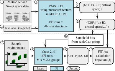
We propose a two-phase CEF-aware FI (shown in Figure 9 and described below), a technique to speed up FI for MPAs.
Phase 1: CEF measurement (Environment independent)
For a given motion set and fault model , Phase 1 performs microarchitecture- or RTL-level FI to find the CEF and critical space of each bit in the swept space data. Algorithm 1 is used for this phase. The number of FI runs for this phase is limited to the number of bits in swept space data of all the motions in the robot’s motion set. The CEF and critical space of all bits are stored to be used in the next phase . Note that environmental information, such as the position of obstacles or the robot, is not needed for this phase, as CEF does not depend upon the environment.
Phase 2: SDC-C probability measurement
A bit flip might lead to an SDC-C depending upon the position of obstacles as shown in Section 3. Since for a dynamic environment, obstacles can appear anywhere in the space, a large number of FI runs with random environmental scenarios are required to measure the SDC-C probability of a bit with statistical significance. In our experiments, the representative environment scenarios are generated using apriori information about the environment, such as the distribution and average number/size of the obstacles.
In Phase 2, we use the CEF information gathered in Phase 1 to speed up the fault analysis. As mentioned, there is a strong (positive) correlation between the CEF and SDC-C probability (Section 6.1.2). Thus, we can speed up the FI experiments many-fold by performing FI for only a subset of bits with a given CEF value to measure the approximate SDC-C probability for all bits with the same CEF. The CEF information gathered in Phase 1 is used to group bits with equal CEF values together . Then, for each CEF value, bits are selected at random . Finally, using multiple sample environment scenarios and FI simulations , the SDC-C probability for each CEF value is measured . Note that is a tunable parameter in the above heuristic. We use the analytical model in Leveugle et al. [63] to determine the value of to measure SDC-C probability with the required confidence level and error margin. The CEF-aware sampling, while being faster than exhaustive FI, may introduce inaccuracies due to the approximations it makes. However, the accuracy can be increased by increasing the value of - we evaluate this trade-off in Section 6.1.1.
To speed up the FI simulation, we further exploit the fault propagation in the studied CDMs. All the accelerators studied in this work use a geometric representation that divides the space into voxels. For a given motion and environment scenario, a non-empty subset of swept space and obstacle occupancy voxels signify potential collision. Thus the effect of a bit flip can be captured by storing the erroneous swept space voxels of the corresponding motion, instead of performing slow microarchitectural and RTL simulations for multiple environmental scenarios. Simple set operations can be used to find the SDC-C probability.
For a given bit flip, an FI simulation is used to find the erroneous swept space (i.e., set of voxels) using Algorithm 1. Line 3 of the Algorithm 1 is modified to use the set of all environment voxels as voxels. Similarly, Lines 8 and 9 are modified to measure the erroneous swept space (i.e., colliding voxels). For each environment scenario, the subsets of obstacles occupancy voxels and erroneous and error-free swept space are measured. If the erroneous subset is empty, but the error-free subset is non-empty, the bit flip will result in an SDC-C. The same strategy is used for exhaustive, statistical, and CEF-aware FI. While we focus on FI to measure CEF and SDC-C probability, we believe that an analytical model can be used to replace the multiple runs and find the relation between critical space and SDC-C probability. We defer this to future work.
Equation 2 is used to calculate the SDC-C probability of a CDM. Here is the set of all bits stored in the CDM’s on-chip memory. CEF() is the CEF value of bit , and is the SDC-C probability for the CEF value .
| (2) |
Table II compares the different phases of CEF-aware FI with exhaustive and uniform random statistical FI approaches for CDM fault characterization and error mitigation. We also use CEF and CEF-aware FI to analyze and compare the effects of microarchitectural design parameters of the CDM, and to derive the principles of resilience-aware MPA design (Section 7).
4.2 FIT Rate Calculation
We derived P() in the previous section (CEF-aware FI). To calculate the FIT rate of a CDM, we modify Equation (1) as:
| (3) |
P() is the probability that a soft error results in an SDC-C (i.e., number of failures per soft error). Since gives the number of soft errors per billion hours per Mbit, the term “P(” gives the number of failures per billion hours per Mbit due to soft errors. Multiplying this term with the total number of bits gives the resultant FIT rate for the entire CDM.
Equation (1) is based on the assumption that a soft error only affects a single execution of the application, and storage elements are reloaded between executions. However, in the MPAs we study, the on-chip data is typically reused across multiple executions of the same application [38, 95, 76, 116] to reduce the DRAM-bandwidth requirement and data movement. In such a case, a bit flip due to a soft error will persist in the buffer and affect multiple executions, until the buffers are reloaded. Therefore, to calculate the effective FIT rate for MPAs with data reuse, we modify Equation 1 and add the term in Equation 3. is the expected number of executions of the application before the bits are reloaded. Thus, “P(” is the number of failures per soft error, and Equation 3 yields the FIT rate for accelerators with data reuse.
5 Experimental Methodology
5.1 Experimental Setup
| Robot | Degrees of freedom | Reach in one direction | Mechanical power (W) |
|---|---|---|---|
| Kinova Jaco2 [59] | 7 | 90 cm | 25 |
| Programmable Universal Machine for Assembly (PUMA) 761 [115] | 6 | 150 cm | 30 |
| AL5D [67] | 4 | 27 cm | 12 |
Table III summarizes the robots used in our experiments. These robotic arms are representative of widely used industrial robots [86, 74], and are also included in larger humanoid robots [4]. Because we did not have access to the real robots, we use the Klampt [43] software simulator to simulate the robot’s movements and the environment- this has also been used in prior work [42, 95, 78].
The environment size for a robot is determined by its reach, and the environment is discretized into a grid of voxels. For each robot, we generate a motion set with poses and motions, using Leven and Hutchinson’s strategy [62], similar to prior work [78]. We use uniform motion sets in all our experiments, i.e., poses are distributed uniformly in the C-space.
To measure the SDC-C probability, we perform FI with a set of random environment scenarios. Each sample environment contains cuboid-shaped randomly placed obstacles, and the length/height/width of each obstacle is cm, which is consistent with other work on motion planning and collision detection [78, 66]. We generate four sets of environments to study the effect of the number of obstacles on the SDC-C probability (Section 6.1.2). We use the label D () to represent a set of environment scenarios, where obstacles occupy an average volume of the environment. The average number of obstacles increases with the value .
5.2 Collision Detection Modules (CDM)
| Accelerator | Representation | Data reuse | #CDCs | Power (W) | Area (mm2) | ECC area/power overhead | TMR area/power overhead |
| A1 [76, 95] | Voxel | Yes | 32,768 | N/A | N/A | 900/720% | 125/100% |
| A2 [76, 95] | Box | Yes | 32,768 | 35 | 400 | 900/720% | 125/100% |
| A3 [66] | Octree | No | 128 | 0.47 | 1.7 | 12/9% | 100/75% |
| [66] | Octree | Yes | 32,768 | 121 | 450 | 12/9% | 100/75% |
| A4 [116] | Flattened Octree | Yes | 32,768 | 20 | - | 12/12% | 200/200% |
Table IV summarizes the four accelerators studied in this work and overll CDM area/power overheads for complete protection of on-chip storage using ECC and TMR error mitigation techniques. These constitute the only published work on ASIC-based programmable, real-time accelerators for motion planning and collision detection, to the best of our knowledge.
We had to build microarchitectural simulators and RTL models of these CDMs ourselves as there was no existing simulator. We synthesized our RTL models using the Synopsys Design Compiler [2] and the OpenRAM Memory Compiler [37] to estimate the area and power of storage elements in CDMs at 45nm technology (FreePDK45 design library [99]). Because we are interested in the relative area and power consumption of different storage elements and combinational circuits, the technology node’s choice should not significantly impact the results.
A1 (Base accelerator): This architecture was proposed by Murray et al. [76], and is based on the earlier proposed accelerator for FPGAs [78]. A motion’s swept space is stored in registers using the 3D Cartesian coordinates of each voxel in the swept space. Figure 5(a) and 5(b) show how a swept space is converted to voxels. The collision detection circuit compares the obstacle occupancy voxels with each voxel in the swept space to find if the motion is in collision with obstacles.
A2 (Spatial locality-aware accelerator): This architecture, proposed by Murray et al. [76] and Sorin et al. [95], is an optimization of A1. There is a significant degree of spatial locality in the voxels in a swept space; hence, contiguous voxels are merged into a larger box. A box can be represented by the coordinates of two diagonal voxels. Figure 5(c) gives an example.
In A1 and A2, all on-chip registers are read in parallel by the collision detection logic, requiring a separate ECC decoder circuit for each register. Hence, the ECC area/power overheads are significantly high for A1 and A2 in Table IV.
A3 (Octree-based accelerator): This architecture was proposed by Lian et al. (2018) [66], and uses the octree structure to store the motion’s swept space (explained in Section 3). Collision detection is performed by traversing the tree to find if obstacle occupancy voxels overlap with the swept space.
The proposed design of A3 uses CDCs, where motions in the motion set are processed for collision detection in batches. Hence, there is no inter-query on-chip data reuse, which results in significant DRAM bandwidth requirement [116]. For comparison, we also study a scaled-up version of A3, called A3, where the number of CDCs is equal to A1 and A2 (), and on-chip data is reused across multiple collision queries, reducing DRAM memory traffic. While the SDC-C probabilities for both A3 and A3 are equal, their FIT rates are different due to differences in the sizes of their components and the value of (Equation 3).
A4 (Flattened octree-based accelerator): This architecture was proposed by Yang et al. (2020) [116], and proposes processing-in-memory for collision detection with a flattened octree-based representation of the swept space. In the flattened octree-based representation, multiple levels of the trees can be flattened in a single level. For example, if all the levels of a 5-level tree are flattened, the resultant tree consists of a single root node with children, where each child node is or specifying occupancy of a single node. Such representation consumes more storage but facilitates efficient processing-in-memory, reducing data-movement overhead significantly.
5.3 Fault Injection (FI)
We use a Python-based implementation of microarchitectural simulators for FI, as RTL-level FI was very slow. We use Dell EMC R440 CPU nodes. However, to validate the FI accuracy of our microarchitectural simulators, we performed RTL-level FI with the Cadence Incisive Functional Safety Simulator [12]). We found that FI using our microarchitectural simulator exhibited correlation with the RTL-level FI.
We represent soft errors as single-bit flips in hardware registers, which is consistent with most other papers studying the effects of soft errors [7, 16, 111, 25]. While we focus on single-bit flips, Equation (2) can be extended to accommodate a multi-bit fault model. We defer this to future work.
For CEF-aware FI, we determine the value of (number of samples) per CEF group required to measure the SDC-C probability with confidence level and error margin [63]. The SDC-C probability and population size of the highest CEF group are used to determine the value of , as these bits contribute the most to the overall SDC-C probability. In our experiments, the value of is for A1 and A4, for A2, and for A3.
5.4 FIT Rate Calculation
To calculate the FIT rate of the accelerators, we use Equation (3), where is the expected number of executions of the application before the bits are reloaded in on-chip storage, and its value depends on the accelerator’s architecture and deployment. Reloading of data can be overlapped with the collision detection to hide the latency of DRAM accesses. We set the value of for the accelerators that exploit inter-query data reuse (A1, A2, A3, and A4), as the power overhead of DRAM accesses is within for refreshing data after collision detection queries. Similarly, is used for the accelerator that does not reuse data across queries (A3). We use FIT/Mb (for 16nm CMOS [64]) in Equation (3). We choose a 16nm technology node, which is used by all the accelerators studied. Note that while the choice of N and affect the absolute values of the FIT rate, they affect neither our fault characterization nor CEF-aware error mitigation.
6 Results
In this section we present our results for fault characterization (Section 6.1) and error mitigation (Section 6.2) using CEF.
6.1 Fault Characterization
6.1.1 CEF-aware FI
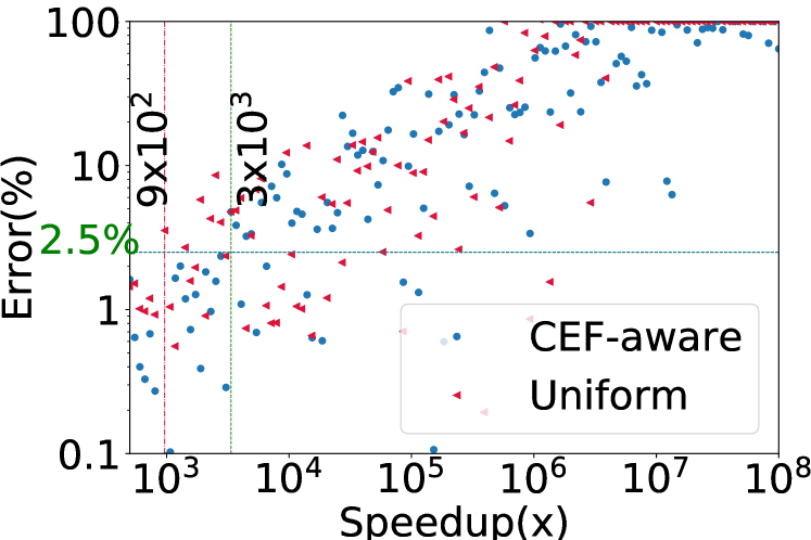
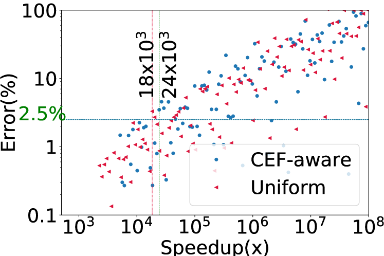
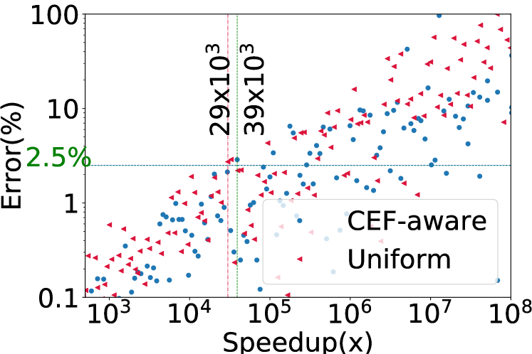
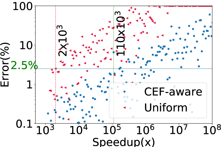
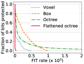
In Section 4, we propose two-phase CEF-aware FI to reduce the number of FI runs. In CEF-aware FI, instead of performing FI for all the bits for multiple environment scenarios, we sample a subset from a group of bits with the same CEF value. This sampling introduces inaccuracies in the measured SDC-C probability and FIT rates compared to exhaustive FI. Figure 10 shows the speedup versus error of the calculated FIT for CEF-aware FI and uniform statistical FI. The speedup is the ratio of the number of exhaustive FI runs to that of CEF-aware FI or uniform statistical FI.
As can be seen from the figure, on average, CEF-aware FI achieves speedup over exhaustive FI (geometric mean) with error margin. The vertical line represents speedup for error less than . The error margin can be reduced further at the cost of more FI trials (Section 4). Uniform statistical FI exhibits a similar speedup as CEF-aware FI over exhaustive FI. Note however that uniform statistical FI cannot be used to find vulnerable bits for selective error mitigation (Table II). The speedup of CEF-aware FI over exhaustive FI is due to two reasons: (1) a significant fraction of bits have CEF equal to , and hence have very low or SDC-C probability. CEF-aware FI ignores these bits for FI, (2) Only a few bits have high CEF and SDC-C probability, and hence contribute the most to overall SDC-C probability. CEF-aware FI segregates such bits and requires fewer samples to measure SDC-C.
Phase 1 of CEF-aware FI consumes , , , and CPU hours for A1, A2, A3, and A4, respectively. Phase 2 of CEF-aware FI consumes less than CPU hours for all accelerators. In contrast, as per our experiments, exhaustive FI takes , , , and CPU hours for A1, A2, A3, and A4, respectively.
6.1.2 Evaluation of reliability metric
As discussed in Section 4, we propose the CEF as a reliability metric for the MPA’s bits. We study the relationship between the CEF and the SDC-C probability to determine if they are indeed positively correlated to demonstrate the validity of CEF metric.
We use the benchmarks [D, D, D, D] (Section 5.1) to study the effect of obstacle occupancy density on the SDC-C probability. Figure 11 shows the SDC-C probability for different accelerators, robots, and benchmarks. For all the benchmarks, the SDC-C probability increases as the CEF increases. Note that as the obstacle occupancy density increases, the SDC-C probability also increases, as there are higher chances that the soft error in a CDM will result in a collision.


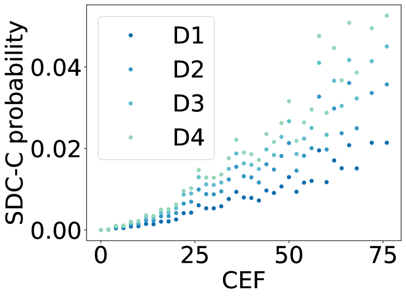
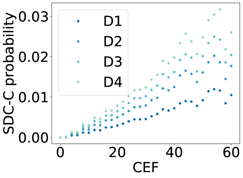
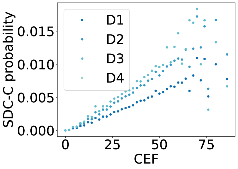
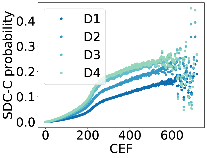
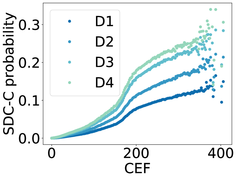
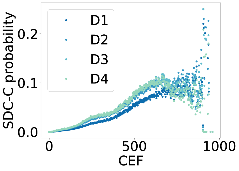
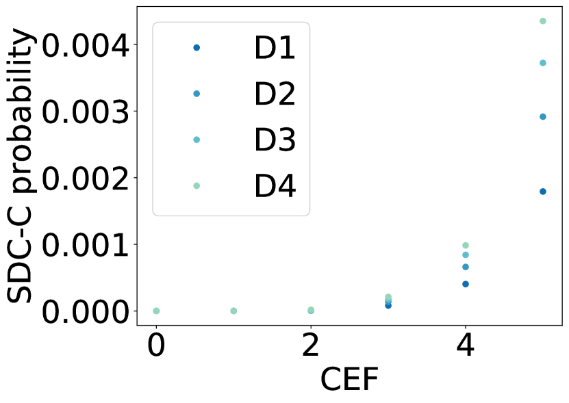
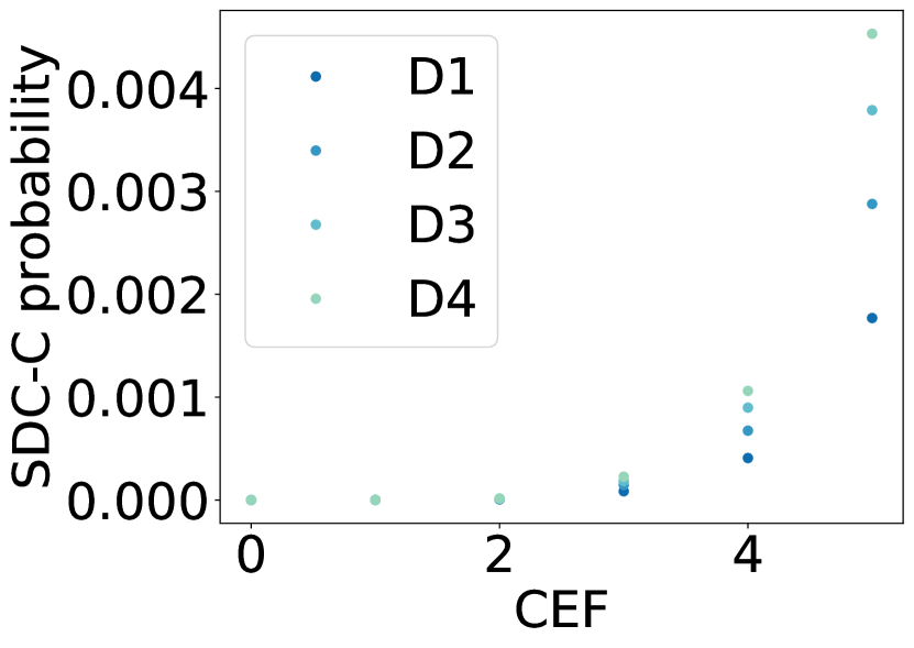
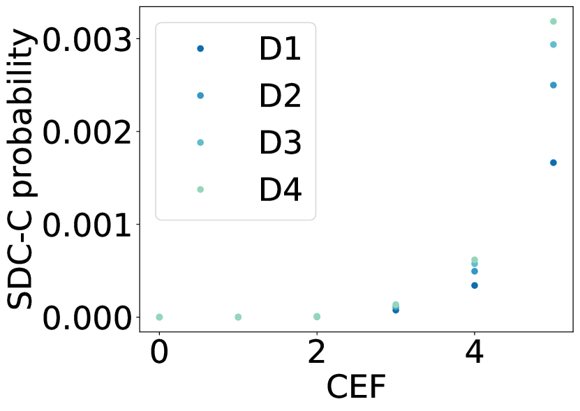
The SDC-C probability is thus strongly positively correlated with CEF values across benchmarks, which signifies that the CEF can be used as a reliability metric for MPAs.
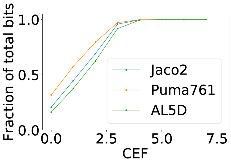
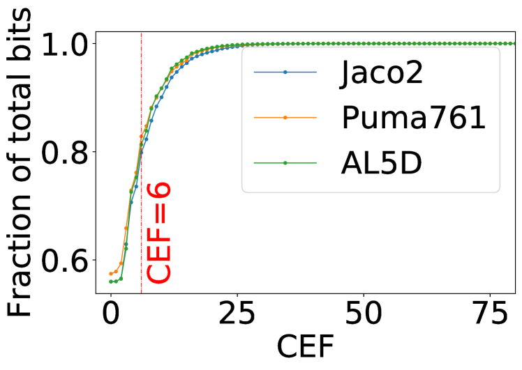
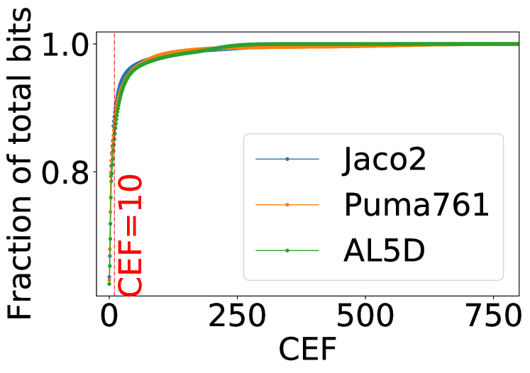
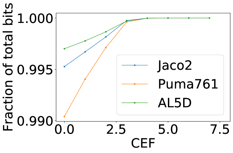
6.1.3 Characterization of CEF
To further understand the contribution of individual bits to the overall SDC-C probability, we group the bits according to their CEFs, and plot the cumulative distribution of bits in the CDM. Figure 12 shows that for all four CDMs, there is a high degree of asymmetry in the distribution of bits according to the CEF. For A1 and A4, and of the total bits have CEF equal to , respectively, and do not need to be protected. On the other hand, for A2, only of the total bits have CEF greater than and significantly contribute to the overall SDC-C probability. Thus, protecting only bits can reduce the FIT rate by , as we show in Section 6.2. Similarly, in A3, only of the total bits have a CEF greater than . We further examine the CEF distribution asymmetry for each accelerator.
A1: In A1, each structure/variable stores a voxel using its coordinates to represent a part of the swept space. A soft error in any bit of the coordinate will result in misrepresentation of that voxel, and so bit position does not affect CEF range (Figure 13(a)).
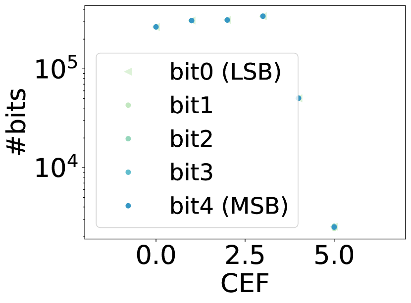
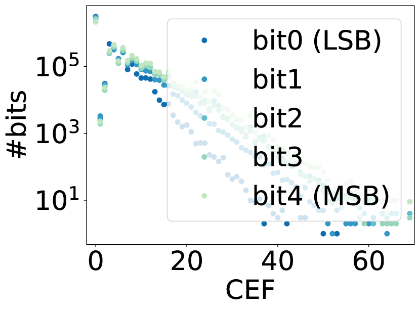
A2: The effect of faults in different bits of coordinates is shown in Figure 13(b). We can see that the CEF range of bits decreases from the most significant bit (MSB) to the least significant bit (LSB), as a fault in the MSB is likely to result in a higher change in the box size represented by a pair of coordinates than LSB. Thus, the number of bits with high CEF values increases from LSB to MSB. For example, the ratio between the number of MSBs () and the number of LSBs () with CEF is .
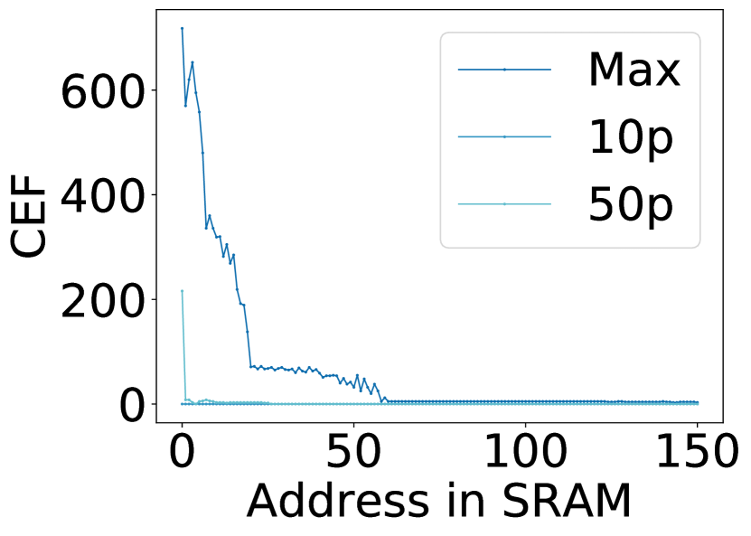
A3: We calculate the range of CEF for bits for different SRAM addresses, as shown in Figure 13(c). All nodes in the octree for a motion’s swept space are stored in the continuous address space of the SRAM; the nodes closer to the octree’s root node that divide the 3D space at a coarser granularity are stored in the lower address range of SRAM. As can be seen, the CEFs of bits with lower SRAM addresses are much higher than those with higher SRAM addresses. For example, the average CEF of bits in SRAM address is that of the average CEF of bits in SRAM address .
A4: A flattened-octree consists of a node for each voxel in the environment. The swept space of a motion in the motion set is a small fraction of the entire environment. Thus, most of the nodes in the flattened octree are empty, and only a small fraction of nodes are occupied. An error in an empty node representation results in false-positive and hence has CEF equal to zero. Due to this, more than of the bits have CEF equal to for A4.
In summary, for all three accelerators, the distribution of the bits as per CEF is highly asymmetric. Hence, the CEF metric facilitates finding the most SDC-C-prone bits in the circuit.
6.2 Error Mitigation Techniques

As described in Section 3.2, we propose CEF-aware selective error mitigation technique. We first evaluate the CEF-aware selection of structures for reliability-aware data placement at deployment time. We further evaluate the area savings achieved by the proposed techniques for accelerators A1, A2, A3, and A4 for different SIL targets at design time. Note that A3’s FIT rate () is well below the highest SIL requirement, and hence it does not need error mitigation. Therefore, we do not consider A3.
6.2.1 CEF-aware selective error mitigation
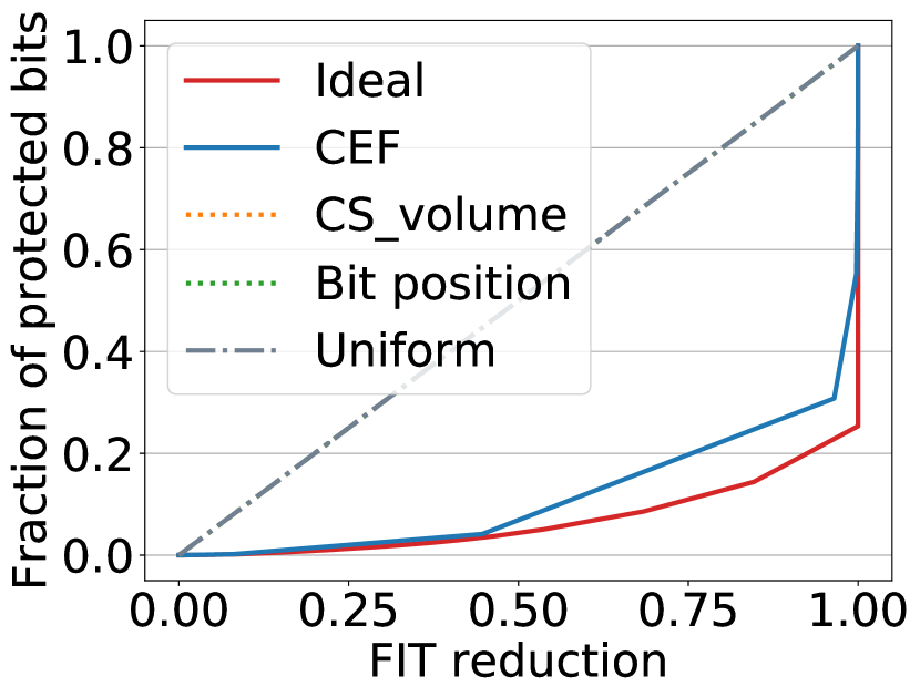
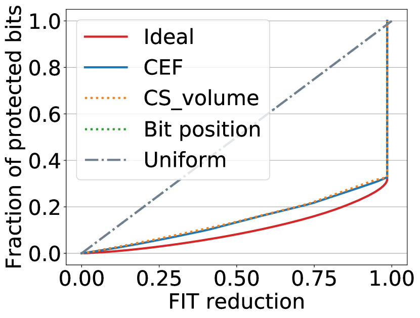
Figure 14 compares the FIT reduction achieved by different selection criteria for the same fraction of protected memory. We assume that protecting a bit reduces its FIT rate to 0 as our aim is to compare different heuristics for selecting the bits to be protected, which is independent of the underlying error mitigation technique. We also compare with another intuitive approach to define the reliability metric that uses the volume of the critical space (CS_volume) instead of exposed surface area. We further discuss the results for A1, A2, , and A4.
A1: We compare our approach with ideal, uniform, bit position, and CS_volume-aware error mitigation. Bit position does not require FI and can be used as a proxy for the vulnerability factor, where the vulnerability of the bits decreases from the MSB to the LSB. Bit position has been previously proposed for selective error mitigation in DNN accelerators [64]. Figure 14(a) shows the fraction of protected bits versus the FIT reduction curve for CEF-aware selection and the other heuristics for A1. The CEF-aware selection of bits results in reduction in the FIT rate on average (geometric mean) for the same amount of protected bits compared to CS_volume-aware, bit position-aware, and uniform selection. The FIT reduction for CEF-aware error mitigation is only lower than the ideal FIT reduction that can be achieved by exhaustive FI that is slower than CEF-aware FI.
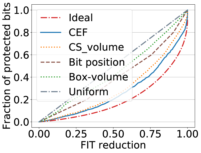
A2: We compare CEF with ideal, uniform, CS_volume, bit position, and box-volume. For A2, a structure represents a box; the volume of the box can be used as the vulnerability factor of the structure. Box-volume is an application-specific heuristic that does not require fault characterization. Figure 14(b) shows the fraction of protected bits versus the FIT reduction for different selection heuristics. The CEF-aware selection of bits results in average , , , and lower FIT rate than CS_volume, bit position, box volume, and uniform selection for the same amount of protected bits. The FIT reduction for CEF-aware error mitigation is only lower than the ideal FIT reduction achieved by exhaustive FI.
Intuitively, one may expect bit position to provide higher benefits than CEF, as typically MSBs are more critical. However, we find that CEF provides a higher reduction in the FIT rate than the bit position, due to two reasons. First, though the bit position captures the failure probability of bits within a structure, it does not capture the relative failure probabilities across different structures. For example, in A2, different boxes cover different numbers of voxels in the swept space that is not covered by other boxes; these voxels contribute to the critical space. The CEF increases as the value increases, and so structures with higher have higher failure probabilities, which is not captured by bit position. Second, the bit position does not consider whether the error will lead to a false-negative or a false-positive. Similarly, box-volume does not necessarily capture the number of critical voxels . In contrast, the CEF captures the relative failure impact of all the structures, and hence provides a higher FIT rate reduction.
: Figure 14(c) shows the fraction of protected bits versus the FIT reduction for different selection criteria in A3. We compare CEF with two heuristics: uniform and access-frequency-based selection. Access-frequency-based selection has been proposed for embedded applications [58, 70]. We find that the CEF-aware selection of bits results in an average and lower FIT rate for the same amount of protected bits compared to CS_volume and access-frequency. This is because the access-frequency-based heuristic captures the failure probability of structures within a single motion, but not the relative failure probabilities across different motions. Further, CEF-aware selection achieves and lower FIT rate than uniform and ideal error mitigation, respectively.
A4: Figure 14(d) compares different selection criteria for A4. We find that the CEF-aware selection of bits results in an average reduction in FIT rate for the same amount of protected bits compared to CS_volume. In the proposed accelerator, the access-frequency for all the bits of a flattened octree is the same, and hence uniform and access-frequency-based selection given the same reduction in the FIT rate. Further, CEF-aware selection achieves and reduction in FIT rate than uniform/access-frequency and ideal error mitigation respectively.
6.2.2 Area savings using CEF-aware error mitigation
Further, we measure the area/power overheads to achieve different SILs using the CEF-aware error mitigation approach. Latch hardening is more suitable than ECC for error mitigation in registers that are accessed in parallel, as adding an ECC encoder-decoder circuit for every register would incur significant area and energy overheads - this is shown in Table IV for A1 and A2 accelerators. Hence, we do not use ECC for A1 and A2 accelerators. We instead use the latch hardening techniques (summarized in Table V) in Sullivan et al. [101] to measure the overheads for A1 and A2.
In contrast, we use ECC (SEC-DED code) for A3 and A4 as these accelerators use SRAM for on-chip storage or DRAM (Table IV). For A3, each entry in SRAM consists of 24 bits. We assume an overhead of 7 bits () to store the ECC bits. For A4, each entry in DRAM consists of bits, with 8 bits overhead for ECC bits. We ignore the area overhead of the error detection/correction circuits themselves. Note that other approaches for ECC [34] can also be combined with CEF-aware selection.
| Latch type | Area Overhead | FIT reduction |
|---|---|---|
| Strike Supression (RCC [91]) | 1.15x | 6.3x |
| Redundant Node (SEUT [91]) | 2x | 37x |
| Triple Module Redundancy (TMR [68]) | 3.5x | 1,000,000x |
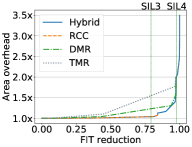
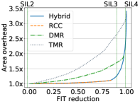
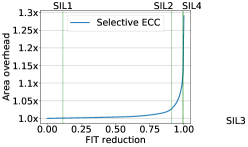
Figure 15 shows the storage area overhead versus FIT reduction for CEF-aware error mitigation for A1, A2, A3, and A4. SIL 1-SIL 4 markers are shown for FIT achievement for the Jaco2 robot and different safety standard levels.
In both A1 and A2, on-chip storage elements consume of the total area/power of the CDM. Thus, applying TMR ( overhead) on all the bits of the CDM incurs area/power overheads. In comparison, for A1, SIL 3 and SIL 4 can be achieved using CEF-aware hybrid latch hardening at and area/power overheads, respectively. Similarly, for A2, SIL 2, SIL 3, and SIL 4 can be achieved at , , and area/power overheads.
For A3, the SRAM contributes to of the total area/power of the CDM, and the complete ECC results in a area/power overhead. However, with CEF-aware selection, SIL 1, SIL 2, SIL 3, and SIL 4 incur , , , and area/power overheads, respectively. For A4, the storage elements of the DRAM contributes to of the total area/power of the CDM, and the blanket application of ECC results in a area/power overhead. In comparison, CEF-aware selection incurs area/power overheads for SIL 4, which is significantly lower than uniform application.
7 Architectural Implications
In this section, we compare the reliabilities of the four CDMs to draw lessons for resilience-aware CDM design. The CDM area is typically dominated by the sequential elements [76, 66], which are more prone to soft errors compared to combinational elements [30, 92, 94]. Error mitigation can incur significant performance, area, and energy overheads (e.g., area and energy for TMR), depending upon the CDM architecture. Hence, we need to consider the overheads of error mitigation for making architectural decisions.
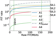
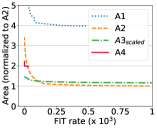
Figure 16(a) compares the FIT rates of accelerators A1, A2, A3, , and A4. Figure 16(b) compares the error mitigation overhead for these accelerators for different FIT rates. Even though has the highest FIT rate (Figure 16(a)), ECC can be used for low overhead error mitigation in as it uses SRAM.
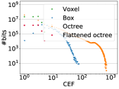
Geometric representation of swept space: Figure 16(c) compares the CEF distribution of different geometric representations used in the CDMs studied for a motion set of the Jaco2 robot.
We find that two aspects of the geometric representation mainly affect the CEF distribution and range: (1) redundancy, and the (2) volume covered by a structure. In the box-based representation, to take advantage of spatial locality, the optimization process converts the swept space into a set of boxes. Each box covers the maximum possible number of voxels in the swept space. This adds redundancy as some voxels are covered by multiple boxes, and are hence not included in critical space. In the octree-based representation, nodes near the root node divide the space at a coarser level and represent a much larger volume. Also, there is no redundancy in the representation. These factors result in an overall higher CEF for octree. Conversely, in voxel- and flattened-octree-based representation, each structure/bit represents a single voxel, and so their CEF is less than (maximum surfaces of a voxel).
Further, geometric representation determines the suitable storage structures and the error mitigation approach. For example, using SRAM/DRAM banks and ECC error mitigation results in lower costs of error mitigation for stringent FIT rate requirements as shown in Figure 16(d) (A3 and A4).
Data reuse: Many accelerators use on-chip buffers to store frequently used data, and exploit data reuse to reduce memory accesses. As a result, a soft error-induced bit flip persists until it is overwritten by reloading the swept space data as explained in Section 4.2. Therefore, if the erroneous data is used for collision queries, the FIT rate increases by times (Equation 3). However, frequent reloading of on-chip data increases DRAM accesses and incurs performance and energy overheads. Thus there is a trade-off between the overhead of error mitigation and DRAM accesses.
8 Related work
Fault Characterization: Several FI tools focus on CPUs and GPUs [104, 65, 41, 110, 25, 79]. TRIDENT [65] uses compiler information to estimate SDC probability without performing FI for CPU. gem5-Approxilyzer [110] uses gem5 simulator [11] for FI, and proposes a methodology for fault site pruning. GPU FI tools [25, 79] use GPGPU-Sim [8] for FI, and propose fault site pruning for GPU SIMT execution model. SASSIFI [41] proposes an instrumentation-based FI tool for NVIDIA GPUs. These tools are useful for fault characterization of general purpose applications, but they cannot be easily applied to robotics accelerators that use specialized microarchitectures and instruction sets. More recent papers have studied the resilience of DNN accelerators [64, 83], and autonomous vehicle systems [9, 52, 53]. We focus, instead, on robotics accelerators processing spatial information. Due to the differences between the datapath and information processed by the DNN accelerators and motion planning accelerators, the fault propagation to the output is significantly different between them.
Another body of work has proposed metrics to characterize the vulnerability of structures to faults [75, 24, 96, 98]. Mukherjee et al. [75] defined the Architectural Vulnerability Factor (AVF), and proposed Architectural Correct Execution analysis (ACE-analysis) to approximate AVF for microprocessor structures [75]. Sridharan et al. [96] proposed the Program Vulnerability Factor (PVF) to decouple the program’s fault-masking effect from that of the microarchitecture, and quantify the vulnerability of a program. Fang et al. extended this work in ePVF [24] to consider only SDC-causing bits. Although useful for CPUs and GPUs, architectural or microarchitectural ACE-analysis is challenging to apply to accelerators due to differences in the ISA and workload. For MPAs in particular, whether a bit is ACE heavily depends upon the position of obstacles, and requires multiple simulations to estimate. The CEF gives a measure of the fraction of runtime for which a bit is ACE without such simulations.
Error Mitigation Techniques: There has been significant work on selective error mitigation techniques for CPUs [85] and GPUs [72, 81, 69]. Mittal et al. [72] proposed compressing similar values in GPUs. Palframan et al. [81] analyzed GPGPU applications and proposed architectural modifications to reduce the magnitude of errors. Unfortunately, these methods are difficult to apply to MPAs due to differences in the ISA and microarchitecture.
Reis et al. [85] and Mahmoud et al. [69] proposed software-level instruction replication to improve the resilience of CPUs and GPUs respectively. However, accelerators typically use complex custom instructions and perform more computations per instruction [17, 66, 78], and hence software-level duplication would result in significant overheads. Li et al. [65] examined the resilience properties of DNN accelerators and proposed a method to protect vulnerable bits. Guan et al. [36] proposed leveraging application-specific data properties in CNNs to minimize the error correction overhead. In contrast, we focus on accelerators processing spatial information. These are very different from DNN/CNN accelerators.
Motion Planning: Many techniques have been proposed to accelerate motion planning on CPUs and GPUs [10, 29, 6, 93]. However, these do not meet the energy and performance requirements of autonomous robots [77, 66]. ASIC-based and FPGA-based MPAs [77, 95, 66, 116] meet real-time constraints, but they focus on performance and energy optimizations, rather than resilience. Other work [102, 18] has studied resilient motion planning under sensor and communication faults, but not soft errors. Note that many of these techniques use the term roadmap instead of motion set to denote the same idea.
9 Conclusions and Future Work
Motion planning is a critical task in autonomous robots, and motion planning accelerators (MPAs) have been proposed to speed it up significantly. Collision detection is the most resource-consuming and safety-critical module in MPAs. In this work, we propose a spatially-aware reliability metric (CEF) for MPAs, based on the exposed surface area of critical space. We propose a CEF-aware mitigation strategy and Fault Injection (FI) method based on this metric. We also find that CEF-aware error mitigation achieves significant FIT (Failures in Time) rate reduction, even while incurring low area and energy overheads. We find that CEF-aware FI results in speedup over exhaustive FI to identify the critical bits. Finally, we identify the architectural design parameters affecting the resilience and error mitigation overheads in MPAs.
There are several possible directions for future work. First, while we focus on single bit flips, both the reliability metric CEF, and the proposed error mitigation and FI methods can be extended to a multi-bit fault model. In particular, Phase 1 of FI, CEF measurement needs to be modified to include multi-bit fault model, where CEF of a bit can be calculated as an average of CEF for different multi-bit fault combinations. Second, while we focused on MPAs, the underlying ideas can be applied to other robotics accelerators that process spatial information. Finally, our observations on the effect of the different design parameters on the resilience and error mitigation overhead open up the direction of “resilience-aware” algorithm-hardware co-design.
References
- [1] 2020 IEEE International Conference on Robotics and Automation, ICRA 2020, Paris, France, May 31 - August 31, 2020. IEEE, 2020. [Online]. Available: https://ieeexplore.ieee.org/xpl/conhome/9187508/proceeding
- [2] “Design compiler,” https://www.synopsys.com/implementation-and-signoff/rtl-synthesis-test/dc-ultra.html, 2020.
- [3] IEEE/RSJ International Conference on Intelligent Robots and Systems, IROS 2020, Las Vegas, NV, USA, October 24, 2020 - January 24, 2021. IEEE, 2020. [Online]. Available: https://doi.org/10.1109/IROS45743.2020
- [4] E. Ackerman, “Jaco is a low-power robot arm that hooks to your wheelchair,” https://spectrum.ieee.org/the-human-os/robotics/medical-robots/robot-arm-helps-disabled-11-year-old-girl-show-horse-in-competition, 2019.
- [5] J. Amanatides and K. Choi, “Ray tracing triangular meshes,” 1995.
- [6] N. Atay and B. Bayazit, “A motion planning processor on reconfigurable hardware,” in Proceedings of IEEE International Conference on Robotics and Automation (ICRA). IEEE, 2006, pp. 125–132.
- [7] F. Ayatolahi, B. Sangchoolie, R. Johansson, and J. Karlsson, “A study of the impact of single bit-flip and double bit-flip errors on program execution,” in Proceedings of the International Conference on Computer Safety, Reliability, and Security, ser. SAFECOMP. Springer-Verlag, 2013, pp. 265–276.
- [8] A. Bakhoda, G. L. Yuan, W. W. L. Fung, H. Wong, and T. M. Aamodt, “Analyzing cuda workloads using a detailed gpu simulator,” in 2009 IEEE International Symposium on Performance Analysis of Systems and Software, 2009, pp. 163–174.
- [9] S. S. Banerjee, S. Jha, J. Cyriac, Z. T. Kalbarczyk, and R. K. Iyer, “Hands off the wheel in autonomous vehicles?: A systems perspective on over a million miles of field data,” ser. DSN. IEEE, 2018, pp. 586–597.
- [10] J. Bialkowski, S. Karaman, and E. Frazzoli, “Massively parallelizing the RRT and the RRT,” ser. IROS, 2011, pp. 3513–3518.
- [11] N. Binkert, B. Beckmann, G. Black, S. K. Reinhardt, A. Saidi, A. Basu, J. Hestness, D. R. Hower, T. Krishna, S. Sardashti, R. Sen, K. Sewell, M. Shoaib, N. Vaish, M. D. Hill, and D. A. Wood, “The gem5 simulator,” SIGARCH Comput. Archit. News, vol. 39, no. 2, p. 1–7, 2011.
- [12] Cadence Design Systems, “Incisive functional safety simulator,” https://www.cadence.com/en_US/home/tools/system-design-and-verification/simulation-and-testbench-verification/incisive-functional-safety-simulator.html, 2020.
- [13] Y. Cao, L. Chen, and Z. Zhang, “Memory design for selective error protection,” in Proceedings of the IEEE International Conference on Computer Design, ser. ICCD, 2015, pp. 133–140.
- [14] R. Cappel and C. Perry-Sullivan, “Yield and cost challenges at 16nm and beyond,” https://sst.semiconductor-digest.com/2016/02/yield-and-cost-challenges-at-16nm-and-beyond/, 2016.
- [15] C.-K. Chang, S. Lym, N. Kelly, M. B. Sullivan, and M. Erez, “Evaluating and accelerating high-fidelity error injection for hpc,” in Proceedings of the International Conference for High Performance Computing, Networking, Storage, and Analysis, ser. SC ’18. IEEE Press, 2018.
- [16] A. Chatzidimitriou, P. Bodmann, G. Papadimitriou, D. Gizopoulos, and P. Rech, “Demystifying soft error assessment strategies on arm cpus: Microarchitectural fault injection vs. neutron beam experiments,” in Proceedings of the International Conference on Dependable Systems and Networks, ser. DSN, 2019, pp. 26–38.
- [17] Y.-H. Chen, J. Emer, and V. Sze, “Eyeriss: A Spatial Architecture for Energy-Efficient Dataflow for Convolutional Neural Networks,” in Proceedings of the International Symposium on Computer Architecture (ISCA), 2016, pp. 367–379, iSSN: 1063-6897.
- [18] A. L. Christensen, R. O’Grady, M. Birattari, and M. Dorigo, “Fault detection in autonomous robots based on fault injection and learning,” Autonomous Robots, pp. 49–67, 2008.
- [19] Daniel Sorin, “Reliable robotics in academia and industry,” Keynote 2019 IEEE 25th International Symposium on On-Line Testing and Robust System Design (IOLTS), 2021.
- [20] Deloitte, “Semiconductors - the next wave,” https://www2.deloitte.com/content/dam/Deloitte/cn/Documents/technology-media-telecommunications/deloitte-cn-tmt-semiconductors-the-next-wave-en-190422.pdf, 2019.
- [21] S. Designline, “Fd soi benefits rise at 14nm,” https://www.eetimes.com/fd-soi-benefits-rise-at-14nm/, 2016.
- [22] Diligent Robotics, “Moxi helps clinical staff do more,” https://diligentrobots.com/moxi, 2020.
- [23] C. Ericson, Real-Time Collision Detection. CRC Press, Inc., 2004.
- [24] B. Fang, Q. Lu, K. Pattabiraman, M. Ripeanu, and S. Gurumurthi, “epvf: An enhanced program vulnerability factor methodology for cross-layer resilience analysis,” in Proceedings of the International Conference on Dependable Systems and Networks, ser. DSN, 2016, pp. 168–179.
- [25] B. Fang, K. Pattabiraman, M. Ripeanu, and S. Gurumurthi, “A systematic methodology for evaluating the error resilience of gpgpu applications.” IEEE Press, 2016, pp. 3397–3411.
- [26] N. Farazmand, R. Ubal, and D. Kaeli, “Statistical fault injection-based avf analysis of a gpu architecure,” IEEE Workshop on Silicon Errors in Logic, 01 2012.
- [27] A. Faust, O. Ramirez, M. Fiser, K. Oslund, A. Francis, J. Davidson, and L. Tapia, “Prm-rl: Long-range robotic navigation tasks by combining reinforcement learning and sampling-based planning,” in IEEE International Conference on Robotics and Automation (ICRA), Brisbane, Australia, 2018, pp. 5113–5120. [Online]. Available: https://arxiv.org/abs/1710.03937
- [28] Gartner, “Gartner forecasts more than 740,000 autonomous-ready vehicles to be added to global market in 2023,” https://www.gartner.com/en/newsroom/press-releases/2019-11-14-gartner-forecasts-more-than-740000-autonomous-ready-vehicles-to-be-added-to-global-market-in-2023, 2019.
- [29] R. Gayle, P. Segars, M. Lin, and D. Manocha, “Path planning for deformable robots in complex environments,” in Robotics: Science and Systems, 2005, pp. 225–232.
- [30] B. Gill, N. Seifert, and V. Zia, “Comparison of alpha-particle and neutron-induced combinational and sequential logic error rates at the 32nm technology node,” in IEEE International Reliability Physics Symposium, 2009, pp. 199–205.
- [31] T. Globe and Mail, “Turning autonomous cars into profit won’t be easy,” https://www.theglobeandmail.com/opinion/article-turning-autonomous-cars-into-profit-wont-be-easy/, 2019.
- [32] Google, “Google patents,” https://patents.google.com/?q=%22collision+detection%22,%22motion+planning%22,%22collision+avoidance%22,%22path+planning%22&q=autonomous,%22self+driving%22,robotics&country=US&status=GRANT&language=ENGLISH&type=PATENT, 2020.
- [33] S. Gottschalk, M. C. Lin, and D. Manocha, “Obbtree: A hierarchical structure for rapid interference detection,” in Proceedings of the Annual Conference on Computer Graphics and Interactive Techniques, ser. SIGGRAPH. Association for Computing Machinery, 1996, pp. 171–180.
- [34] J. Gracia-Moran, L. Saiz-Adalid, J. Baraza-Calvo, and P. Gil, “Correction of adjacent errors with low redundant matrix error correction codes,” in 2018 Eighth Latin-American Symposium on Dependable Computing (LADC), 2018, pp. 107–114.
- [35] J. Groopman, “Robots that care,” https://www.newyorker.com/magazine/2009/11/02/robots-that-care, 2009.
- [36] H. Guan, L. Ning, Z. Lin, X. Shen, H. Zhou, and S.-H. Lim, “In-Place Zero-Space Memory Protection for CNN,” in Advances in Neural Information Processing Systems, H. Wallach, H. Larochelle, A. Beygelzimer, F. d. Alché-Buc, E. Fox, and R. Garnett, Eds. Curran Associates, Inc., 2019, pp. 5734–5743.
- [37] M. R. Guthaus, J. E. Stine, S. Ataei, B. Chen, B. Wu, and M. Sarwar, “OpenRAM: An open-source memory compiler,” in 2016 IEEE/ACM International Conference on Computer-Aided Design (ICCAD), Nov. 2016, pp. 1–6, iSSN: 1558-2434.
- [38] S. Han, X. Liu, H. Mao, J. Pu, A. Pedram, M. A. Horowitz, and W. J. Dally, “EIE: Efficient Inference Engine on Compressed Deep Neural Network,” in Proceedings of the International Symposium on Computer Architecture (ISCA), vol. 16, 2016, pp. 243–254.
- [39] Y. Han, Y. Yang, X. Chen, and S. Lian, “Dadu series - fast and efficient robot accelerators,” in 2020 IEEE/ACM International Conference On Computer Aided Design (ICCAD), 2020, pp. 1–8.
- [40] S. K. S. Hari, M. Sullivan, T. Tsai, and S. W. Keckler, “Making convolutions resilient via algorithm-based error detection techniques,” IEEE Transactions on Dependable and Secure Computing, pp. 1–1, 2021.
- [41] S. K. S. Hari, T. Tsai, M. Stephenson, S. W. Keckler, and J. Emer, “SASSIFI: An architecture-level fault injection tool for GPU application resilience evaluation,” in IEEE International Symposium on Performance Analysis of Systems and Software, ser. ISPASS, 2017, pp. 249–258.
- [42] K. Hauser, “Lazy collision checking in asymptotically-optimal motion planning,” in Proceedings of the IEEE International Conference on Robotics and Automation, ser. ICRA, 2015, pp. 2951–2957.
- [43] K. Hauser, Robust Contact Generation for Robot Simulation with Unstructured Meshes. Springer, Cham, 2016, pp. 357–373.
- [44] K. K. Hauser and J. Latombe, “Integrating task and prm motion planning : Dealing with many infeasible motion planning queries,” 2009.
- [45] J. L. Hennessy and D. A. Patterson, Computer Architecture, a quantitative approach. Morgan Kaufmann, 2012.
- [46] V. Honkote, D. Kurian, S. Muthukumar, D. Ghosh, S. Yada, K. Jain, B. Jackson, I. Klotchkov, M. R. Nimmagadda, S. Dattawadkar, P. Deshmukh, A. Gupta, J. Timbadiya, R. Pali, K. Narayanan, S. Soni, S. Chhabra, P. Dhama, N. Sreenivasulu, J. Kollikunnel, S. Kadavakollu, V. D. Sivaraj, P. Aseron, L. Azarenkov, N. Robinson, A. Radhakrishnan, M. Moiseev, G. Nandakumar, A. Madhukumar, R. Popov, K. P. Sahu, R. Peguvandla, A. D. R. Ruiz, M. Bhartiya, A. Srinivasan, and V. De, “2.4 a distributed autonomous and collaborative multi-robot system featuring a low-power robot soc in 22nm cmos for integrated battery-powered minibots,” in 2019 IEEE International Solid- State Circuits Conference - (ISSCC), 2019, pp. 48–50.
- [47] IEC, “Functional safety and iec 61508,” http://www.iec.ch/functionalsafety/, 2020.
- [48] IFR, “Executive summary world robotics 2019 industrial robots,” https://ifr.org/downloads/press2018/ExecutiveSummaryWR2019IndustrialRobots.pdf, 2019.
- [49] IFR, “Executive summary world robotics 2019 service robots,” https://ifr.org/downloads/press2018/Executive_Summary_WR_Service_Robots_2019.pdf, 2019.
- [50] C. L. Jackins and S. L. Tanimoto, “Oct-trees and their use in representing three-dimensional objects,” Computer Graphics and Image Processing, pp. 249–270, 1980.
- [51] L. Jaillet and T. Siméon, “A prm-based motion planner for dynamically changing environments,” 2004 IEEE/RSJ International Conference on Intelligent Robots and Systems (IROS) (IEEE Cat. No.04CH37566), vol. 2, pp. 1606–1611 vol.2, 2004.
- [52] S. Jha, S. Banerjee, T. Tsai, S. K. S. Hari, M. B. Sullivan, Z. T. Kalbarczyk, S. W. Keckler, and R. K. Iyer, “ML-Based Fault Injection for Autonomous Vehicles: A Case for Bayesian Fault Injection,” in Proceedings of the International Conference on Dependable Systems and Networks, ser. DSN, 2019, pp. 112–124.
- [53] S. Jha, S. S. Banerjee, J. Cyriac, Z. T. Kalbarczyk, and R. K. Iyer, “AVFI: Fault Injection for Autonomous Vehicles,” ser. DSN-W. IEEE, 2018, pp. 55–56.
- [54] N. P. Jouppi, C. Young, N. Patil, D. Patterson, G. Agrawal, R. Bajwa, S. Bates, S. Bhatia, N. Boden, A. Borchers, R. Boyle, P.-l. Cantin, C. Chao, C. Clark, J. Coriell, M. Daley, M. Dau, J. Dean, B. Gelb, T. V. Ghaemmaghami, R. Gottipati, W. Gulland, R. Hagmann, C. R. Ho, D. Hogberg, J. Hu, R. Hundt, D. Hurt, J. Ibarz, A. Jaffey, A. Jaworski, A. Kaplan, H. Khaitan, D. Killebrew, A. Koch, N. Kumar, S. Lacy, J. Laudon, J. Law, D. Le, C. Leary, Z. Liu, K. Lucke, A. Lundin, G. MacKean, A. Maggiore, M. Mahony, K. Miller, R. Nagarajan, R. Narayanaswami, R. Ni, K. Nix, T. Norrie, M. Omernick, N. Penukonda, A. Phelps, J. Ross, M. Ross, A. Salek, E. Samadiani, C. Severn, G. Sizikov, M. Snelham, J. Souter, D. Steinberg, A. Swing, M. Tan, G. Thorson, B. Tian, H. Toma, E. Tuttle, V. Vasudevan, R. Walter, W. Wang, E. Wilcox, and D. H. Yoon, “In-datacenter performance analysis of a tensor processing unit,” in Proceedings of the International Symposium on Computer Architecture (ISCA), June 2017, pp. 1–12.
- [55] L. Kavraki, P. Svestka, J. Latombe, and M. Overmars, “Probabilistic roadmaps for path planning in high-dimensional configuration spaces,” IEEE Transactions on Robotics and Automation, pp. 566 – 580, 1996.
- [56] L. E. Kavraki and S. M. LaValle, Motion Planning. Berlin, Heidelberg: Springer Berlin Heidelberg, 2008, pp. 109–131.
- [57] T. Kevan, “Will robots find a place in the smart home?” https://www.digitalengineering247.com/article/will-robots-find-a-place-in-the-smart-home, 2019.
- [58] S. Kim and A. Somani, “Area efficient architectures for information integrity in cache memories,” in Proceedings of the 26th International Symposium on Computer Architecture (Cat. No.99CB36367), 1999, pp. 246–255.
- [59] KINOVA, “Kinova jaco assistive robot,” https://www.kinovarobotics.com/sites/default/files/KINO-2018-Bro-Assistive-ZH_YUL-06-R-Web.pdf, 2018.
- [60] S. M. LaValle, “Motion planning,” IEEE Robotics Automation Magazine, pp. 79–89, 2011.
- [61] S. M. LaValle, Planning Algorithms. USA: Cambridge University Press, 2006.
- [62] P. Leven and S. Hutchinson, “A framework for real-time path planning in changing environments,” The International Journal of Robotics Research, pp. 999–1030, 2002.
- [63] R. Leveugle, A. Calvez, P. Maistri, and P. Vanhauwaert, “Statistical fault injection: Quantified error and confidence,” in Proceedings of the Conference on Design, Automation and Test in Europe, ser. DATE. European Design and Automation Association, 2009, pp. 502–506.
- [64] G. Li, S. K. S. Hari, M. Sullivan, T. Tsai, K. Pattabiraman, J. Emer, and S. W. Keckler, “Understanding error propagation in deep learning neural network (DNN) accelerators and applications,” in Proceedings of the International Conference for High Performance Computing, Networking, Storage and Analysis, ser. SC. Association for Computing Machinery, 2017, pp. 1–12.
- [65] G. Li, K. Pattabiraman, S. K. S. Hari, M. Sullivan, and T. Tsai, “Modeling Soft-Error propagation in programs,” ser. DSN. IEEE, 2018, pp. 27–38.
- [66] S. Lian, Y. Han, X. Chen, Y. Wang, and H. Xiao, “Dadu-p: A scalable accelerator for robot motion planning in a dynamic environment,” in Proceedings of the Annual Design Automation Conference, ser. DAC. Association for Computing Machinery, 2018.
- [67] Lynxmotion, “Al5d robot arm specs,” http://www.lynxmotion.com/driver.aspx?Topic=specs04, 2020.
- [68] R. E. Lyons and W. Vanderkulk, “The use of triple-modular redundancy to improve computer reliability,” IBM Journal of Research and Development, vol. 6, no. 2, pp. 200–209, 1962.
- [69] A. Mahmoud, S. K. S. Hari, M. B. Sullivan, T. Tsai, and S. W. Keckler, “Optimizing software-directed instruction replication for GPU error detection,” in Proceedings of the International Conference for High Performance Computing, Networking, Storage and Analysis, ser. SC, Dallas, Texas, 2018, pp. 1–12.
- [70] M. Mehrara and T. Austin, “Exploiting selective placement for low-cost memory protection,” Transactions on Architecture and Code Optimization, pp. 1–24, 2008.
- [71] S. Mitra, T. Karnik, N. Seifert, and M. Zhang, “Logic soft errors in sub-65nm technologies design and CAD challenges,” in Proceedings of the Annual Design Automation Conference, 2005, pp. 2–4, iSSN: 0738-100X.
- [72] S. Mittal, H. Wang, A. Jog, and J. S. Vetter, “Design and Analysis of Soft-Error Resilience Mechanisms for GPU Register File,” in 2017 30th International Conference on VLSI Design and 2017 16th International Conference on Embedded Systems (VLSID), 2017, pp. 409–414.
- [73] P. Montesinos, W. Liu, and J. Torrellas, “Using register lifetime predictions to protect register files against soft errors,” in Proceedings of the IEEE/IFIP International Conference on Dependable Systems and Networks, ser. DSN, 2007, pp. 286–296.
- [74] H. P. Moravec, “Puma,” https://www.britannica.com/technology/PUMA-robot, 2021.
- [75] S. S. Mukherjee, C. Weaver, J. Emer, S. K. Reinhardt, and T. Austin, “A systematic methodology to compute the architectural vulnerability factors for a high-performance microprocessor,” in Proceedings of the ACM/IEEE International Symposium on Microarchitecture, ser. MICRO. IEEE Computer Society, 2003, pp. 29–40.
- [76] S. Murray, W. Floyd-jones, G. Konidaris, and D. J. Sorin, “A Programmable Architecture for Robot Motion Planning Acceleration,” in International Conference on Application-specific Systems, Architectures and Processors, ser. ASAP. IEEE, 2019, pp. 185–188.
- [77] S. Murray, W. Floyd-Jones, Y. Qi, D. J. Sorin, and G. Konidaris, “Robot motion planning on a chip,” in Robotics: Science and Systems, 2016.
- [78] S. Murray, W. Floyd-Jones, Y. Qi, G. Konidaris, and D. J. Sorin, “The microarchitecture of a real-time robot motion planning accelerator,” in Proceedings of the ACM/IEEE International Symposium on Microarchitecture, ser. MICRO. IEEE Press, 2016.
- [79] B. Nie, L. Yang, A. Jog, and E. Smirni, “Fault site pruning for practical reliability analysis of GPGPU applications,” in Proceedings of the ACM/IEEE International Symposium on Microarchitecture (MICRO), ser. MICRO-51, 2018, pp. 749–761.
- [80] OHMNILABS, “The importance of low-cost robotics,” https://ohmnilabs.com/content/the-importance-of-low-cost-robotics/, 2019.
- [81] D. J. Palframan, N. S. Kim, and M. H. Lipasti, “Precision-aware soft error protection for GPUs,” in Proceedings of the International Symposium on High-Performance Computer Architecture (HPCA), 2014, pp. 49–59.
- [82] J. Ramsey, “40https://www.autoblog.com/2020/05/11/car-electronics-cost-semiconductor-chips/, 2020.
- [83] B. Reagen, U. Gupta, L. Pentecost, P. Whatmough, S. K. Lee, N. Mulholland, D. Brooks, and G.-Y. Wei, “Ares: A framework for quantifying the resilience of deep neural networks,” in Proceedings of the Annual Design Automation Conference, ser. DAC. Association for Computing Machinery, 2018.
- [84] Realtime Robotics, Inc., “Realtime robotics,” https://rtr.ai/, 2020.
- [85] G. Reis, J. Chang, N. Vachharajani, R. Rangan, and D. August, “SWIFT: software implemented fault tolerance,” in International Symposium on Code Generation and Optimization, 2005, pp. 243–254.
- [86] R. B. Review, “Kinova honored for jaco robotic arm,” https://www.roboticsbusinessreview.com/health-medical/kinova_honored_for_jaco_robotic_arm/, 2014.
- [87] M. Riera, A. Canal, Ramon anf Gonzalez, J. Abella, M. Anglada, and M. Torrents, “Soft-error vulnerability evolution:a 4d study (bulk/soi, planar/finfet),” in International Workshop on Reliability and Aging in Forthcoming Electronic Systems, 2015.
- [88] Y. Roth-Tabak and R. Jain, “Building an environment model using depth information,” Computer, vol. 22, pp. 85–90, 1989.
- [89] M. Rouman, “Siemens and realtime robotics accelerate the integration of industrial robotic workcells,” https://blogs.sw.siemens.com/tecnomatix/siemens-and-realtime-robotics-accelerate-the-integration-of-industrial-robotic-workcells/, 2020.
- [90] O. Salzman, “Sampling-based robot motion planning,” Communications of the ACM, pp. 54–63, 2019. [Online]. Available: https://doi.org/10.1145/3318164
- [91] N. Seifert, V. Ambrose, B. Gill, Q. Shi, R. Allmon, C. Recchia, S. Mukherjee, N. Nassif, J. Krause, J. Pickholtz, and A. Balasubramanian, “On the radiation-induced soft error performance of hardened sequential elements in advanced bulk cmos technologies,” in IEEE International Reliability Physics Symposium, 2010, pp. 188–197.
- [92] N. Seifert, B. Gill, S. Jahinuzzaman, J. Basile, V. Ambrose, Q. Shi, R. Allmon, and A. Bramnik, “Soft error susceptibilities of 22 nm tri-gate devices,” IEEE Transactions on Nuclear Science, vol. 59, no. 6, pp. 2666–2673, 2012.
- [93] X. Shi, L. Cao, D. Wang, L. Liu, G. You, S. Liu, and C. Wang, “HERO: Accelerating Autonomous Robotic Tasks with FPGA,” ser. IROS, 2018, pp. 7766–7772.
- [94] P. Shivakumar, M. Kistler, S. W. Keckler, D. Burger, and L. Alvisi, “Modeling the effect of technology trends on the soft error rate of combinational logic,” in Proceedings International Conference on Dependable Systems and Networks, ser. DSN, 2002, pp. 389–398.
- [95] D. J. Sorin, G. Konidaris, W. Floyd-Jones, and S. Murray, “Motion Planning for Aotonomous Vehicles and Reconfigurable Motion Planning Processor,” U.S. Patent 20 190 163 191, 2019.
- [96] V. Sridharan and D. R. Kaeli, “Eliminating microarchitectural dependency from architectural vulnerability,” in Proceedings of the International Symposium on High-Performance Computer Architecture, ser. HPCA, 2009, pp. 117–128.
- [97] V. Sridharan, N. DeBardeleben, S. Blanchard, K. B. Ferreira, J. Stearley, J. Shalf, and S. Gurumurthi, “Memory Errors in Modern Systems: The Good, The Bad, and The Ugly,” ACM SIGPLAN Notices, vol. 50, pp. 297–310, 2015.
- [98] V. Sridharan and D. R. Kaeli, “Using hardware vulnerability factors to enhance AVF analysis,” in Proceedings of the IEEE international symposium on Computer architecture, ser. ISCA. Saint-Malo, France: Association for Computing Machinery, Jun. 2010, pp. 461–472.
- [99] J. E. Stine, I. D. Castellanos, M. H. Wood, J. Henson, F. Love, W. R. Davis, P. D. Franzon, M. Bucher, S. Basavarajaiah, J. Oh, and R. Jenkal, “FreePDK: An open-source variation-aware design kit,” in IEEE International Conference on Microelectronic Systems Education (MSE), 2007, pp. 173–174.
- [100] D. Stow, Y. Xie, T. Siddiqua, and G. H. Loh, “Cost-effective design of scalable high-performance systems using active and passive interposers,” in 2017 IEEE/ACM International Conference on Computer-Aided Design (ICCAD), 2017, pp. 728–735.
- [101] M. Sullivan, B. Zimmer, S. Hari, T. Tsai, and S. W. Keckler, “An Analytical Model for Hardened Latch Selection and Exploration,” ser. SELSE, 2016.
- [102] X. Sun, R. Nambiar, M. Melhorn, Y. Shoukry, and P. Nuzzo, “DoS-Resilient Multi-Robot Temporal Logic Motion Planning,” in Proceedings of IEEE International Conference on Robotics and Automation (ICRA), 2019, pp. 6051–6057.
- [103] Tesla, “Future of driving,” https://techxplore.com/news/2020-04-robots-heroes-war-coronavirus.html, 2020.
- [104] S. Tselonis and D. Gizopoulos, “GUFI: A framework for GPUs reliability assessment,” ser. ISPASS. IEEE, 2016, pp. 90–100.
- [105] Uber Advanced Technologies Group, “We believe in the power of technology,” https://www.uber.com/ca/en/atg/technology/, 2020.
- [106] Universal Robots, “The ur5e - a flexible collaborative robot arm,” https://www.universal-robots.com/products/ur5-robot/, 2020.
- [107] USPTO, “Uspto patent full-text and image database,” http://patft.uspto.gov/netahtml/PTO/search-adv.htm, 2020.
- [108] A. Vallero, S. Tselonis, D. Gizopoulos, and S. Di Carlo, “Multi-faceted microarchitecture level reliability characterization for NVIDIA and AMD GPUs,” ser. VTS. IEEE, 2018, pp. 1–6.
- [109] G. van den Bergen, “Efficient collision detection of complex deformable models using aabb trees,” Journal of Graphics Tools, pp. 1–13, 1998.
- [110] R. Venkatagiri, K. Ahmed, A. Mahmoud, S. Misailovic, D. Marinov, C. W. Fletcher, and S. V. Adve, “gem5-approxilyzer: An open-source tool for application-level soft error analysis,” in Proceedings of the International Conference on Dependable Systems and Networks, ser. DSN, 2019, pp. 214–221.
- [111] R. Venkatagiri, K. Swaminathan, C. Lin, L. Wang, A. Buyuktosunoglu, P. Bose, and S. Adve, “Impact of software approximations on the resiliency of a video summarization system,” in Proceedings of the International Conference on Dependable Systems and Networks, ser. DSN, 2018, pp. 598–609.
- [112] X. Vera, J. Abella, J.-A. Pineiro, A. Gonzalez, and R. Ronen, “Selectively protecting a register file,” U.S. Patent 20 080 155 375, 2008.
- [113] Washington State University, “Smart home tests first elder care robot,” https://www.sciencedaily.com/releases/2019/01/190114130913.htm, 2019.
- [114] M. Wayland, “Toyota’s per-car profits lap detroit’s big 3 automakers,” https://www.detroitnews.com/story/business/autos/2015/02/22/toyota-per-car-profits-beat-ford-gm-chrysler/23852189/, 2015.
- [115] Wikipedia, “Programmable universal machine for assembly,” https://en.wikipedia.org/wiki/Programmable_Universal_Machine_for_Assembly/, 2020.
- [116] Y. Yang, X. Chen, and Y. Han, “Dadu-cd: Fast and efficient processing-in-memory accelerator for collision detection,” in 2020 57th ACM/IEEE Design Automation Conference (DAC), 2020, pp. 1–6.
- [117] D. H. Yoon and M. Erez, “Virtualized ecc: Flexible reliability in main memory,” IEEE Micro, pp. 11–19, 2011.
- [118] R. Zheng and M. C. Huang, “Redundant memory array architecture for efficient selective protection,” in Proceedings of the International Symposium on Computer Architecture, ser. ISCA ’17. Association for Computing Machinery, 2017, p. 214–227.