Microstructural analysis of GaN films grown on (1 0 0) MgF2 substrate by 4D nanobeam diffraction and energy-dispersive X-ray spectrometry
I Additional NBED patterns
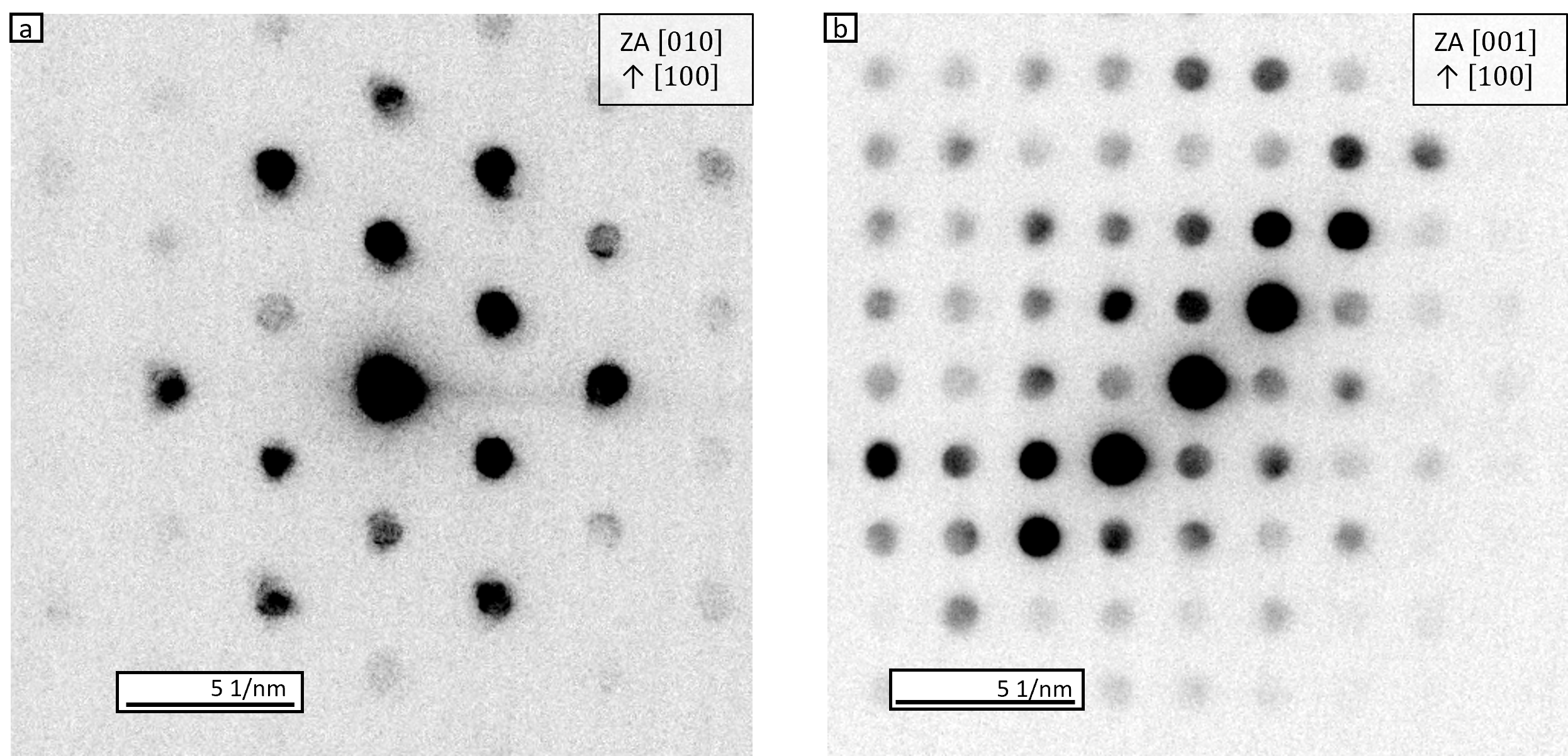
As an addition to the presented NBED patterns in the main text in Fig. S1 representative patterns of the MgF2 substrate for both orientations are shown. These patterns confirm the orientation of the substrate as (100) MgF2.
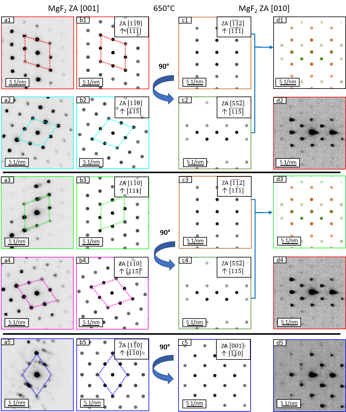
As the mainly observed NBED patterns are the same for both temperatures they are only shown for the sample grown at 525 ∘C in the main text. In Fig. S2 representative NBED patterns of the five mainly observed orientation of c-GaN are shown in the same way together with the calculated patterns as in Fig. 4 in the main text.
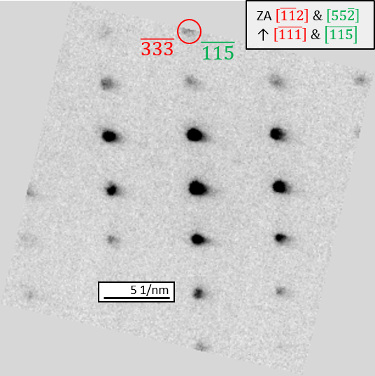
In Fig. S3 a NBED pattern of the 525 ∘C sample is shown which is rotated to have the out of plane direction vertical. Instead to the other presented patterns the edges are not cut to show that we observe at the edge of this pattern the spot. As this pattern is a superposition of at least two c-GaN orientations having both a spot at these position.
II Mathematical treatment of twinning: cubic systems
Cubic GaN crystallizes as the fcc zincblende structure. In such systems, twinning planes are of type . There are several ways to describe twinning; here we choose a mirror operation at the twinning plane. For this purpose, we seek for the transformation matrix such that
| (1) |
where and denote vectors in the untwinned and twinned crystal, respectively.
In order to determine , we need to know the transformation of three linearly independent vectors, i.e.
| (2) |
It is straightforward to show that this leads to a matrix equation
| (3) |
where
| (4) |
and
| (5) |
There are different – crystallographically equivalent – ways to describe twinning in cubic systems, i.e.
-
1.
Mirror operation at twinning plane (normal : ). This way, we have and directions perpendicular to are unaffected. Ex.: will be transformed into , whereas and are unaffected. These considerations immediately show that successive twinning on planes containing the same direction – as e.g. and share [110] – conserves this direction. Hence, in this case, untwinned crystal, primary twin and secondary twin share this direction, or related to electron diffraction, share this zone axis.
-
2.
Rotation about by 180. Same transformation except that all directions are replaced by their opposite direction.
-
3.
For also the rotation about by also leads to an equivalent transformation.
Here, we will follow route 1, i.e. mirror operation. Hence, we have
| (6) |
II.1 Relevant cases for the c-GaN system
II.1.1 Twinning on = (111)
Following the above considerations, we obtain
| (7) |
which finally yields
| (8) |
II.1.2 Twinning on =
An analogous treatment yields
| (9) |
II.1.3 Twinning on =
An analogous treatment yields
| (10) |
II.1.4 Twinning on =
An analogous treatment yields
| (11) |
II.2 Secondary twins
As secondary twins, we denote the result of successive twinning operations on two (different) twin planes followed by , i.e. the transformation
| (12) |
It is important to realize that for a single twin, we have
| (13) |
whereas for secondary twins, we have
| (14) |
II.3 Twin transforms of specific directions
Here, results of twin transforms of specific directions in a cubic system are summarized. It should be noted, that these calculations are independent of any epitaxial relation to a substrate. For subsequent comparison to experimental data, however, certain projections need to be calculated. Table S1 summarizes results of two consecutive twin operations on different planes. As noted above, consecutive twinning on identical twin planes will restore the untwinned orientation (compare also Table S1).
In line with NBED data shown in Figs. 3 and 4 of the publication, consecutive twinning on planes sharing the same direction have to be considered. e.g. and sharing the direction. Inspection of the table (6th row) shows that [111] will be transformed parallel to [511] (twinning on and consecutive twinning on (111) transforms it parallel to , which is off as observed in experiments. In the same way (not shown in Table S1), will be transformed parallel to (twinning on (111)) and further into , which is off .
Table S1 further allows deduction of primary and secondary twinning on other planes, not sharing . It turns out, that the considered directions mostly transform into high-indexed directions and in all cases, no additional diffraction spots will appear. Valuable insight is gained from the fact that diffraction spots can only be observed along or zone axes. This allows for estimation of the amount of twinning on other planes by creating a virtual dark field by a (virtual) ring aperture containing spots. The dark regions of the resulting virtual dark field can be assumed to belong partly to the other planes.
| PT | ST | [001] | [10] | [110] | [111] | [] |
|---|---|---|---|---|---|---|
| (111) | (—) | 1 0 | ||||
| (111) | ||||||
| (—) | ||||||
| (—) | ||||||
| (—) | ||||||
II.4 Reciprocal space maps (RSM) and electron diffraction patterns
Up to this point, only twinning transforms have been discussed without referring to special epitaxial relations and cross-section directions used for obtaining electron diffraction patterns or X-ray RSM. Experimentally, cross-sections along MgF2 [010] and [001] have been analyzed revealing two main orientational relationships:
GaN (110) MgF2 (100) with GaN MgF2 [001] (in short: c-GaN [001](100) MgF2) and GaN (111) MgF2 (100) with GaN MgF2 [001] (in short:
c-GaN [001](100)MgF2) and their respective variants as a result of the twofold symmetry of the substrate surface (compare also Table S2). For the former (subsequently denoted as ’2/2-epitaxy’), this variant is fully equivalent due to the twofold symmetry of the layer along [110]. For the latter (subsequently denoted as ’2/3-epitaxy’), the variant corresponds to a twinning transform with (111) c-GaN as a twinning plane, hence the notation as ’2/-epitaxy’.
| phase / epitaxy | MgF2 | GaN | [%] | ||||
|---|---|---|---|---|---|---|---|
| UVW | HKL | D [nm] | uvw | hkl | d [nm] | ||
| c-GaN / 2/2 epitaxy | 100 | 020 | 0.2310 | 110 | 002 | 0.2260 | 2.2 |
| 002 | 0.1525 | 20 | 0.1598 | -4.8 | |||
| c-GaN / 2/3 epitaxy | 100 | 020 | 0.2310 | 111 | 0.1846 | 20.0† | |
| 002 | 0.1525 | 0.1598 | -4.8 | ||||
| c-GaN / 2/ epitaxy | 100 | 020 | 0.2310 | 0.1846 | 20.0† | ||
| 002 | 0.1525 | 0.1598 | -4.8 | ||||
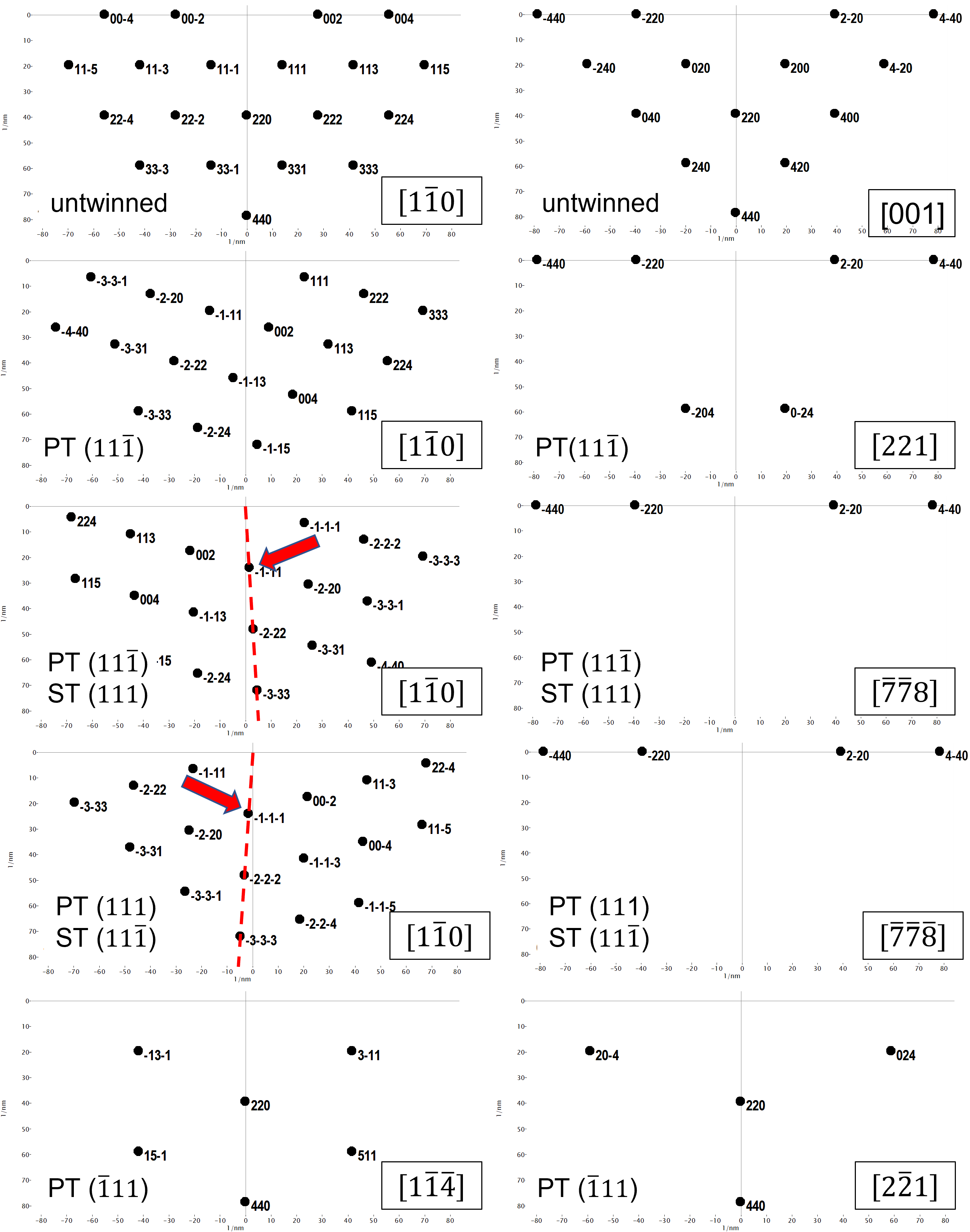
Subsequently, electron diffraction patterns (or equivalently RSM) are presented for the two systems in order to show possible spot overlap and additional spots possibly specific for certain variants. Fig. S4 summarizes specific diffraction patterns for the 2/2-epitaxy. Comparing the different patterns, the result summarized in Table S1 are visualized. An important observation is the tilt of and planes by , which explains the splitting of (111) spots observed by X-ray diffraction (compare Fig.8 in the manuscript), which averages over many twin domains, i.e. effectively superimposes individual patterns.
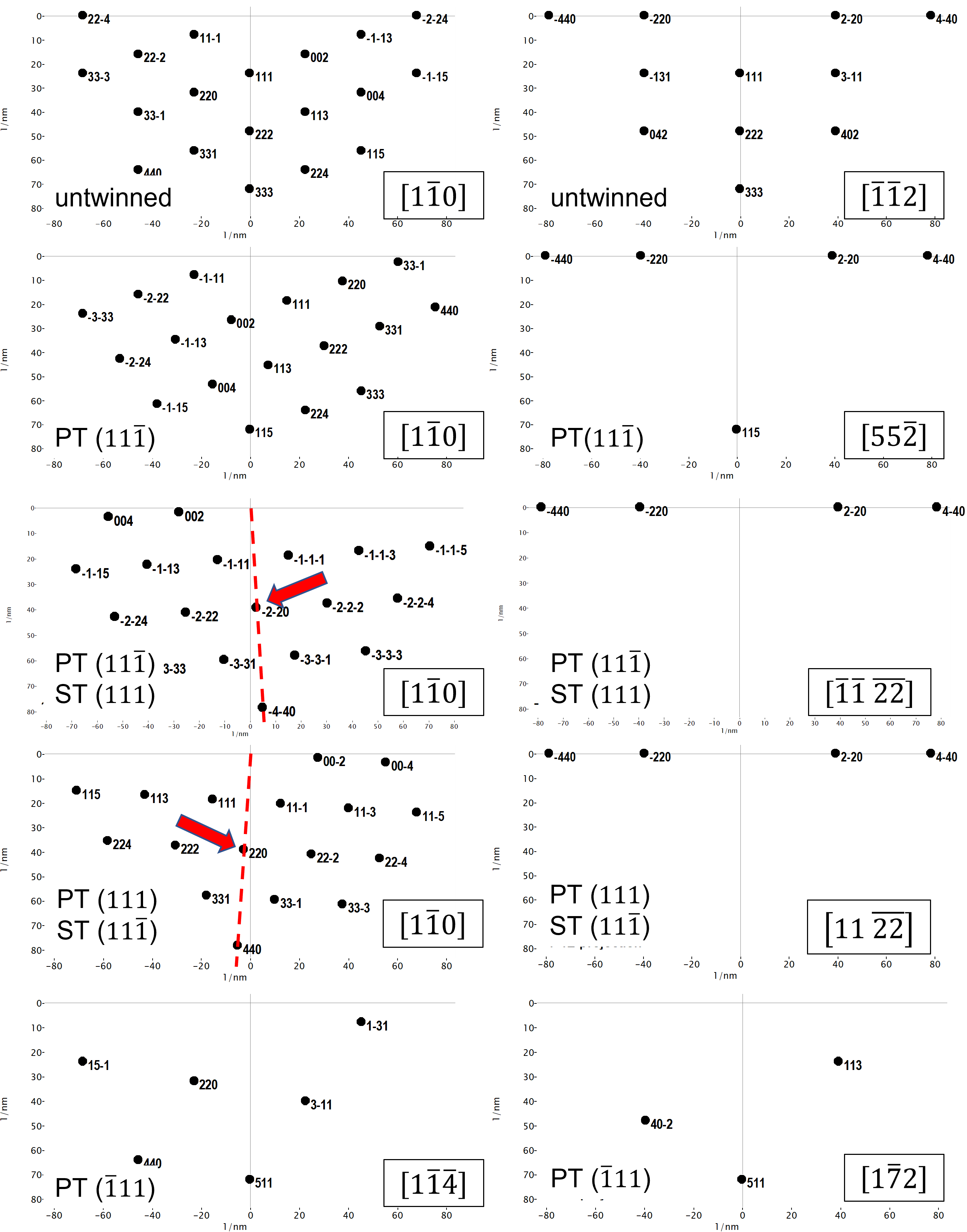
Fig. S5 summarizes specific diffraction patterns for the 2/3-epitaxy; note, that patterns due to 2/-epitaxy are simply obtained by rotation about the Qz axis (compare e.g. rows 3 and four). Comparing the different patterns, the result summarized in Table S1 are visualized. An important observation is the tilt of and planes by , which should give rise to splitting of (220) spots in X-ray diffraction reciprocal space maps.