Response of the GAGG(Ce) scintillator to charged particles compared with the CsI(Tl) scintillator
Abstract
GAGG(Ce) is a novel scintillator with a fast response and high light output without a hygroscopic nature. It is expected to be a useful detector for charged particles at high-counting rates. However, the response of the GAGG(Ce) scintillator to charged particles has not been fully examined. In the present work, the light output and energy resolution of the GAGG(Ce) scintillator were measured for protons and alpha particles at –68 MeV and –54 MeV as well as gamma rays at keV from a 137Cs source. The results were compared with those of the CsI(Tl) scintillator. The scintillation efficiencies of the GAGG(Ce) and CsI(Tl) scintillators were obtained and parametrized as a function of linear energy transfer .
1 Introduction
Ce-doped Gd3Al2Ga3O12 [GAGG(Ce)] is a novel scintillation material developed by Institute for Materials Research, Tohoku University and Furukawa CO., LTD [1, 2, 3]. The main decay time constant of the GAGG(Ce) scintillator is reported as 60–100 ns [4, 5, 6], thus it seems to be appropriate for measurements at high-counting rates. The GAGG(Ce) scintillator has been employed as gamma-ray detectors for numerous purposes such as Compton camera [7, 8], positron emission tomography [9], and radiation imaging [10].
So far, the Tl-doped alkali iodides such as NaI(Tl) and CsI(Tl) scintillators have been commonly used not only for gamma-ray measurements [11, 12] but also for charged particle detections [13, 14, 15]. The properties of the GAGG(Ce) scintillator are compared with those of the NaI(Tl) and CsI(Tl) scintillators in Table 1 [16].
The NaI(Tl) scintillator has a light output of about 40,000 photons/MeV. The scintillation light of NaI(Tl) can be efficiently detected with a photomultiplier tube owing to its emission peak located at 415 nm. The decay time of the NaI(Tl) scintillator is faster than that of the CsI(Tl) scintillator, making it tolerant of high-counting rates. However, the NaI(Tl) scintillator has a strong hygroscopic nature, and it must be packed in an airtight container, which makes a dead layer in charged particle detections.
The CsI(Tl) scintillator has a high light output larger than the NaI(Tl) scintillator. Because its emission wavelength matches to the Si-based photon detectors such as a PIN photo diode and avalanche photo diode (APD), the CsI(Tl) scintillators are often used with them. It has a slight hygroscopic nature but can be used without a package to prevent hygroscopy, which makes it useful for charged particle detection. The major disadvantage of the CsI(Tl) scintillator is its slow decay time of the scintillation, thus it is not suitable for a measurement at high-counting rates.
Among the three scintillators, presented in Table 1, the GAGG(Ce) scintillator has the fastest decay time. The light output and energy resolution for gamma rays are comparable with those of the NaI(Tl) and CsI(Tl) scintillators. Moreover, it does not have a hygroscopic nature and can be used without any package. Therefore, the GAGG(Ce) scintillator would be useful for a charged particle detection at high-counting rates. However, the response of the GAGG(Ce) scintillator to charged particles has not been fully examined. The particle identification between alpha particles at MeV from an 241Am source and gamma rays at keV from a 137Cs source by a pulse shape discrimination was investigated in Refs. [17, 16]. The light output and non-proportionality for low-energy alpha particles at 1.5–8.8 MeV were reported in Ref. [18].
| GAGG(Ce) | NaI(Tl) | CsI(Tl) | |
| Density (g/cm3) | 6.63 | 3.67 | 4.53 |
| Light output (photons/MeV) | 46,000 | 40,000 | 50,000 |
| Emission-peak wavelength (nm) | 530 | 415 | 540 |
| Decay time (ns) | 95(79), 351(21) | 230 | 680 |
| Hygroscopic nature | None | Strong | Slight |
In this article, we report the responses of the GAGG(Ce) scintillator to protons and alpha particles at –68 MeV and –54 MeV. The results were compared with those of the CsI(Tl) scintillator. First, we acquired the pulse shapes from the GAGG(Ce) and CsI(Tl) scintillators for gamma rays. Then we investigated the pulse heights and the energy resolutions with changing the time constants of a shaping amplifier. Finally, we obtained the incident-energy dependence of the light outputs using the protons and alpha particles. The scintillation efficiencies of the GAGG(Ce) and CsI(Tl) scintillators were analyzed as a function of the linear energy transfer (LET) .
2 Performance test with a 137Cs gamma-ray source
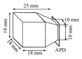
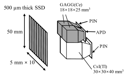
The responses of the GAGG(Ce) and CsI(Tl) scintillators to gamma rays were investigated using a 137Cs gamma-ray source. Figure 1 shows the geometry of the GAGG(Ce) and CsI(Tl) scintillators used in the measurement. The crystals have sizes of 18 18 25 mm3. The back side of the crystals was tapered so that the crystals can be attached to photon detectors with a sensitive area of 10 10 mm2. The photon detectors were HAMAMATSU S8664-1010 APDs. These crystals were frosted on the surface and wrapped with 65-m-thick enhanced specular reflector (ESR) films [19] to increase the light collection efficiency.
The electrical signal from the APD was amplified by a Mesytec MPR-16 preamplifier followed by a Mesytec MSCF-16 shaping amplifier. The decay time of the preamplifier is 25 s. The shaping amplifier has a 5th order CR-RC5 filter circuit with a selectable time constant of 0.25, 0.50, 1.0, and 2.0 s. The MSCF-16 shaping amplifier also has a function of a fast amplifier with a shorter time constant for timing measurements. The pulse height from the MSCF-16 shaper output was measured with a Mesytec MADC-32 peak sensing analog to digital converter (ADC).
2.1 Pulse shape
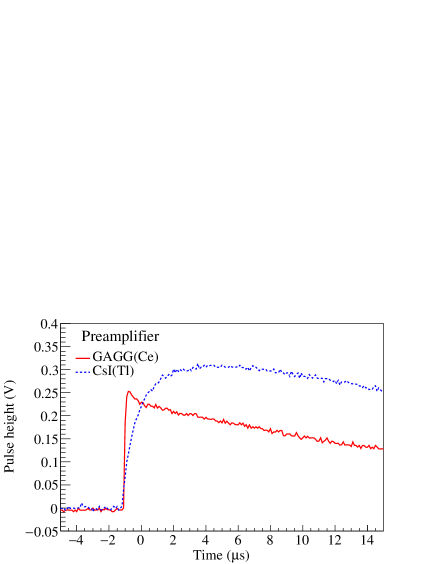
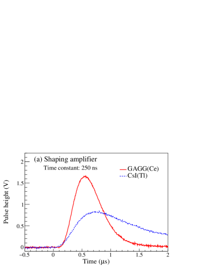
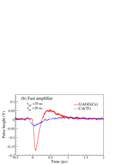
The pulse shapes from the preamplifier and shaping amplifier for 662-keV gamma rays were acquired with an oscilloscope. The time constant of the shaping amplifier was set at 250 ns. The differentiation and integration time constants of the fast amplifier were set at ns and ns, respectively.
The output signals from the preamplifier are shown in Fig. 2. The red solid and blue dashed lines represent the pulse shapes of the GAGG(Ce) and CsI(Tl) scintillators, respectively. The pulse heights of the preamplifier outputs in Fig. 2 are comparable between the GAGG(Ce) and CsI(Tl) scintillators. This means that the light outputs from the GAGG(Ce) and CsI(Tl) scintillators for gamma rays are comparable. We define the signal rise time as the period of time during which the pulse height changes from 10 to 90 of the peak. The rise time of the GAGG(Ce) scintillator was 0.13 s, which is about 1/10 of that of the CsI(Tl) scintillator of 1.86 s. This rise time reflects the decay times of the scintillation process.
The outputs from the fast and shaping amplifiers in MSCF-16 are shown in Fig. 3. Although the light outputs from the GAGG(Ce) and CsI(Tl) scintillators are comparable, the pulse heights of the shaping and fast amplifiers of the GAGG(Ce) scintillator are about twice and four times larger than those of the CsI(Tl) scintillators, respectively. Because the decay time of the GAGG(Ce) scintillator is much shorter than that of the CsI(Tl) scintillator, the GAGG(Ce) scintillator has the advantage that its output signal is efficiently processed with the shaping and fast amplifiers with a short time constant for high-counting-rate measurements.
|
|
2.2 Pulse height and energy resolution
The pulse-height spectra of the scintillators for gamma rays from the 137Cs source are shown in Fig. 4. The red and blue spectra represent the GAGG(Ce) and CsI(Tl) scintillators, respectively. The time constant of the MSCF-16 shaping amplifier was set at 2 s. The pulse height and the energy resolution were estimated by fitting the spectra by Gauss functions.
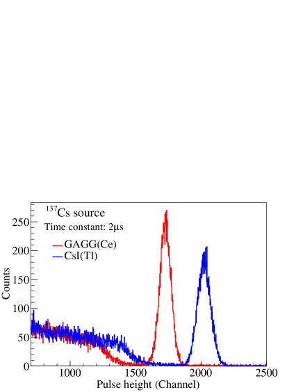
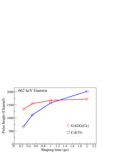
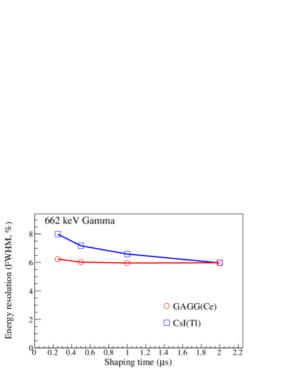
Figure 5 shows the measured pulse heights (left) and energy resolutions (right) in FWHM when the time constant of the MSCF-16 shaping amplifier was set at 0.25, 0.50, 1.0, and 2.0 s. The red circles and the blue squares represent the GAGG(Ce) and CsI(Tl) scintillators, respectively. The pulse heights of both the scintillators decrease with the shorter shaping times. The pulse height of the GAGG(Ce) scintillator decreases less than that of the CsI(Ce) scintillator. The energy resolutions of the gamma-ray measurements with the GAGG(Ce) and CsI(Tl) scintillators are comparable when the time constant is set at 2.0 s. This means that the intrinsic energy resolutions of the scintillators are almost the same. On the other hand, when the time constants become shorter, the energy resolution with the CsI(Tl) scintillator is worse than that with the GAGG(Ce) scintillator because the pulse height of CsI(Tl) from the shaping amplifier with a short time constant is no longer sufficiently larger than the photodetector noise. The energy resolution with the GAGG(Ce) scintillator shows little change with a shorter time constant of the amplifier, making it useful in high-counting-rates experiments where the time constant must be short to avoid pile-ups.
|
|
3 Performance test with proton and alpha beams
We investigated the responses of the GAGG(Ce) and CsI(Tl) scintillators to charged particles using 70-MeV proton and alpha beams. The beams were scattered from targets and the scattered particles were detected by the scintillators. The energy of the particles at the detectors was changed by placing the detectors at different angles. We measured the relative light outputs of the scintillators as a function of the incident energy.
3.1 Experimental procedure
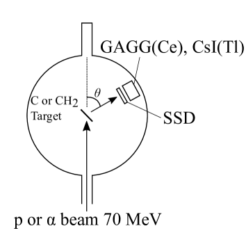
The measurement was carried out at the 41 course of Cyclotron and Radioisotope Center (CYRIC), Tohoku University. Figure 6 shows a schematic view of the experimental setup. The proton and alpha beams were accelerated to 70 MeV with a MeV azimuthally varying-field cyclotron and focused on a natural carbon or a CH2 foil target installed at the center of the scattering chamber. The scattered particles were detected by an – telescope consisting of the GAGG(Ce) and CsI(Tl) scintillators and a silicon strip detector (SSD).
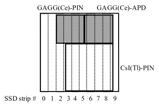
The setup of the – telescope is shown in Fig. 7. For the detector at the front, we used a SSD with a thickness of 500 m. The sensitive area of the SSD was 50 50 mm2. The SSD sensitive area was divided into 10 vertical strips whose widths are 5 mm. The SSD was used to measure the energy loss and the hit position of the charged particles on the scintillators. The three strips (2–4 or 6–8) on the SSD were used for the GAGG(Ce) scintillators, and the five strips (4–8) were used for the CsI(Tl) scintillator.
For the detectors, we used two GAGG(Ce) and one CsI(Tl) scintillators. The GAGG(Ce) scintillators were the same as those used in the gamma-ray measurement reported in Sec. 2. One GAGG(Ce) was attached to the APD as in Sec. 2 and the other was attached to a HAMAMATSU S3590-08 PIN photo diode with a sensitive area of 10 10 mm2. Using the two GAGG(Ce) scintillators, we confirmed that the photodetector resolutions with the APD and PIN photo diode were almost same for relatively high-energy particles inducing much larger signals than the noise. Unlike the GAGG(Ce) scintillators, the CsI(Tl) scintillator was different from one used in the gamma-ray measurement. The CsI(Tl) scintillator has a volume of 30 30 40 mm3 and the back side of the crystal was tapered to attach to a HAMAMATSU S3204-08 PIN photo diode with a sensitive area of 18 18 mm2. These crystals were frosted on the surface and wrapped with the ESR films in the same manner as in the gamma-ray measurement. We note that the measurements using the gamma-ray source reported in Sec. 2 were carried out after the present experiment in CYRIC. Because the CsI(Tl) scintillator with the same geometry as the GAGG(Ce) scintillator was prepared after the experiment in CYRIC, it was not used in the present measurement.
Because the gain of the APD changes depending on temperature, the temperature of the detectors was monitored with a Pt-100 thermometer during the measurement. The temperature was stable at . The same preamplifier, shaping amplifier, and ADC modules as those described in Sec. 2 were used. The preamplifier was installed inside the scattering chamber to reduce electrical noise.
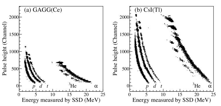
Figure 8 shows the pulse height of the output signals from the shaping amplifier for the GAGG(Ce) and CsI(Tl) scintillators versus the energy measured by the SSD when the alpha beams bombarded the CH2 target. The left and right figures represent the GAGG(Ce) and CsI(Tl) scintillators, respectively. In both of the scintillators, events due to protons, deuterons, tritons, 3He, and alpha particles were clearly separated. In the following analysis, we selected only the proton and alpha-particle events.
By changing the angle of the detectors ( in Fig. 6), the energy of the incident particles to the scintillators was varied in an increment by about 5 MeV. For the measurement with the proton beam, we analyzed the elastic scattering and the C elastic scattering. For the measurement with the alpha beam, we analyzed the C elastic scattering and the C inelastic scattering to the state at MeV. The incident energies to the scintillators were calculated from the scattering kinematics taking into account the energy losses through the SSD and the ESR film. The energy losses were estimated using the SRIM simulation code [20].
3.2 Pulse height and energy resolution
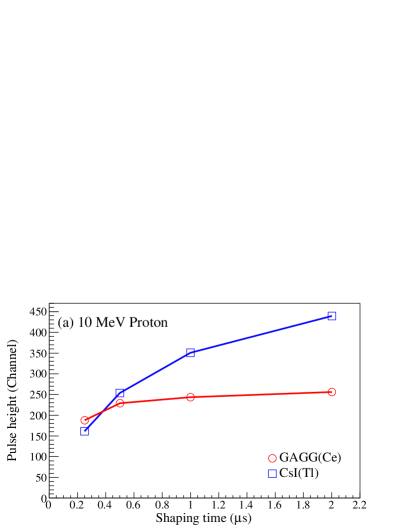
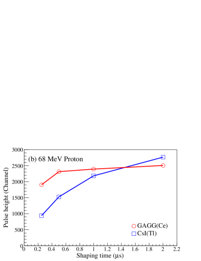
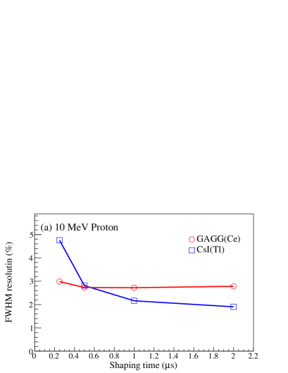
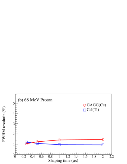
Figures 9 and 10 present the shaping time dependencies of the pulse heights and the energy resolutions (FWHM) for protons at (a) 10 MeV and (b) 68 MeV. The red circles and the blue squares represent the GAGG(Ce) and CsI(Tl) scintillators, respectively. The shaping time was set at 0.25, 0.50, 1.0, and 2.0 s.
The pulse height of the CsI(Tl) scintillator drastically decreases with the shorter shaping times compared with the GAGG(Ce) scintillator. The significant reduction of the pulse height of the CsI(Tl) scintillator is due to its decay time longer than the GAGG(Ce) scintillator. This reduction was observed both for protons and gamma-rays as seen in Figs. 5 and 9. The slopes of the CsI(Tl) scintillator for the protons at 68 MeV and gamma rays are slightly steeper than that for the protons at 10 MeV. This is explained by the fact that the decay time of the CsI(Tl) scintillator becomes slightly longer as the LET decreases [21].
When the shaping time is set at 2 s, the pulse height of the GAGG(Ce) scintillator for the 68-MeV protons is slightly smaller than that of the CsI(Tl) scintillator as seen in Fig. 9 (b). On the other hand, the pulse height of the GAGG(Ce) scintillator for the 10-MeV protons is much smaller compared with the CsI(Tl) scintillator as seen in Fig. 9 (a). This suggests that the light output of the GAGG(Ce) scintillator quenches as the LET becomes large. This quenching effect is discussed in detail in Sec. 3.4.
When the pulse height is sufficiently high, the energy resolution is determined by the statistical fluctuation of the scintillation process rather than the photodetector noise. This is why the energy resolutions of the GAGG(Ce) and CsI(Tl) scintillators for the 68-MeV protons are less dependent on the shaping times as seen in Fig. 10 (b). When the proton energy is at 10 MeV, however, the energy resolution of the CsI(Tl) scintillator becomes worse with shorter shaping time as seen in Fig. 10 (a) affected by the noise because the pulse height of the CsI(Tl) scintillator severely decreases. The energy resolution of the GAGG(Ce) scintillator at 68 MeV becomes slightly better with shorter shaping time because the dominant frequency component of the noise is filtered out at the shorter shaping time.
|
|
|
|
3.3 Relative light output for protons and alpha particles
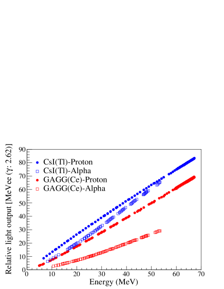
The light outputs from the GAGG(Ce) and CsI(Tl) scintillators for protons and alpha particles can be evaluated as relative values to those for electrons in units of MeV electron equivalent (MeVee). 1 MeVee corresponds to the light output when 1 MeV of energy is given to a scintillator by electrons. We determined the relative light outputs for protons and alpha particles by comparing the pulse heights with that for a gamma ray at 2.62 MeV emitted after the beta decay of 208Tl from the thorium series under the assumption that the light output for the gamma ray is 2.62 MeVee. The relative light outputs as a function of the incident energy for the protons at –68 MeV and alpha particles at –54 MeV are shown in Fig. 11. The red solid circles and open squares represent the relative light outputs from the GAGG(Ce) scintillator for protons and alpha particles, respectively, whereas the blue solid circles and open squares represent those from the CsI(Tl) scintillator for the protons and alpha particles. The unit of the vertical axis is given in MeVee (: 2.62). The suffix of (: 2.62) means that the calibration reference of the relative light output is a gamma ray at 2.62 MeV.
As discussed in Ref. [22], the light outputs for the charged particles relative to gamma rays would be different depending on the time constant of the shaping amplifier used. In the present measurement, the time constants of the shaping amplifier or the GAGG(Ce) and CsI(Tl) scintillators were 0.25 and 2.0 s, respectively.
The relative light outputs from the GAGG(Ce) scintillator are systematically smaller than those from the CsI(Tl) scintillator. The relative light outputs for the alpha particles, which provide larger LETs than protons, are smaller than those for the protons from the same scintillator. This shows that the light outputs for both of the scintillators are quenched with larger LETs.
3.4 Scintillation efficiency
In order to evaluate the quenching effect of the scintillators, we investigated the relation between the light output per unit energy loss (scintillation efficiency) and the LET . The values were obtained using the light outputs for two different energies measured at different angles as
| (3.1) |
and are the relative light output and the incident energy to the scintillators when the telescope detector was placed at the angle . The light-collection efficiency slightly changes depending on the hit position of the incident particle on the scintillator. Therefore, and were determined for particles which hit the same strip of the SSD at different angles.
The values were evaluated at the mean energy using the two different codes; SRIM and PSTAR [23]. The values in the CsI(Tl) scintillator given by the SRIM code were systematically 3 smaller than those by the PSTAR code. In the present analysis, we used the values given by the SRIM code because the GAGG(Ce) scintillator was not included in the material listing of the PSTAR code.
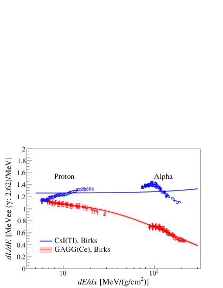
The correlation between the and values is shown in Fig. 12. The red circles and the blue squares represent the GAGG(Ce) and CsI(Tl) scintillators, respectively. The data points at MeV/(g/cm2) were obtained with the alpha beam, while those at MeV/(g/cm2) were obtained with the proton beam. The uncertainties of were estimated from the residuals when the data points in Fig. 11 were fitted by polynomials. These uncertainties are considered to stem from inaccuracies of scattering angles caused by misalignment of the detector position and non-uniformity of the light-collection efficiency. It should be noted that the values for protons and alpha particles behave as a smooth function of for each scintillator as shown in Fig. 12. The scintillation efficiency of the CsI(Tl) scintillator is larger than unity. Similar result is reported for 12C ions in Ref. [24]. The scintillation efficiency of the GAGG(Ce) scintillator is also larger than unity at MeV/(g/cm2).
It would be useful to determine an empirical formula of as a function of . Birks introduced the following formula to investigate the scintillation efficiency of organic scintillators [25]:
| (3.2) |
In this formula, it is assumed that the number of scintillation photons per unit length produced by the incident particle is proportional to the energy loss per unit length . The denominator was empirically introduced so that the scintillation efficiency decreases with larger values. The factor is called Birks factor. This Birks formula reasonably fits the experimental results of the anthracene scintillators. Dividing this equation by , the relation between and is obtained as
| (3.3) |
The Birks function was fitted to the experimental data of the GAGG(Ce) and CsI(Tl) scintillators as plotted with the solid lines in Fig. 12. The obtained parameters are tabulated in Table 2. The Birks formula reasonably reproduces the vs plot of the GAGG(Ce) scintillator. The error band around the red solid line for the GAGG(Ce) scintillator indicate the confidence interval of the fit at 68. On the other hand, the Birks formula cannot reproduce the non-monotonous trend for the CsI(Tl) scintillator at all.
| GAGG(Ce) | CsI(Tl) | |
| Birks | ||
| Modified Birks | ||
| 1.11 | 1.74 | |
| 3.7 | ||
| Romero | ||
| 4.68 | 4.20 | |
| -5.84 | -5.32 | |
| 3.81 | 3.53 | |
| -1.22 | -1.11 | |
Koba et al. modified the Birks formula as
| (3.4) |
to reproduce the scintillation efficiency of the CsI(Tl) scintillator [24]. Romero et al. introduced another empirical formula to fit the scintillation efficiency of the NaI(Tl) scintillator [26]:
| (3.5) |
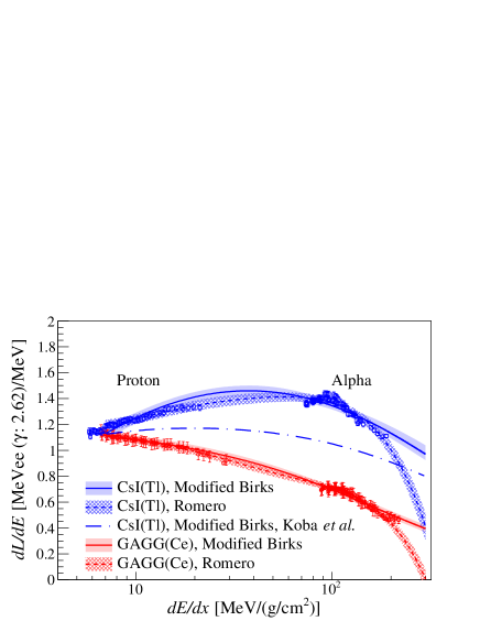
In the present analysis, we fitted Eqs. (3.4) and (3.5) to of the GAGG(Ce) and CsI(Tl) scintillators at –200 MeV/(g/cm2) as shown in Fig. 13. The fitted lines are drawn with the solid lines (modified Birks) and the dashed lines (Romero) associated with the error bands. The blue dash-dotted line represents the previous fit result with the modified Birks formula for the CsI(Tl) scintillator reported by Koba et al. [24]. The present result of the CsI(Tl) scintillator is systematically 20 larger than the previous result. This discrepancy is probably because of the concentration of Tl doped in the CsI crystal. Murray and Meyer reported that the values vary up to 100 with the Tl concentration from 0.01 to 0.2 [27].
The scintillation efficiency of the CsI(Tl) scintillator is more stable over the wide range than the GAGG(Ce) scintillator, making the CsI(Tl) scintillator useful as a charged particle detector. However, its slow response would cause a pile-up at high-counting rates. The GAGG(Ce) scintillator is a good candidate for light charged particles such as protons and alpha particles thanks to the fast response as well as the good energy resolution although the scintillation efficiency notably decreases with the larger .
Recently, we constructed a GAGG(Ce) based light-ion telescope (Gion) which consists of 24 GAGG(Ce) scintillators with the same geometry as shown in Fig. 1 and a double-sided silicon strip detector. Gion was successfully employed to detect recoil protons emitted from 12C() reaction in inverse kinematics. Using Gion, the rare radiative-decay probability of the state at MeV in 12C was determined to estimate the triple alpha reaction rate in high temperature environments [28].
4 Summary
The light output and energy resolution of the GAGG(Ce) and CsI(Tl) scintillators were compared using 662-keV gamma-ray quanta from a 137Cs source, 2615-keV gamma-ray quanta of 208Tl from environmental radioactivity, and accelerated beams. For gamma rays, the light outputs from the GAGG(Ce) and CsI(Tl) scintillators are comparable. The energy resolution of the two scintillators are also comparable when the time constant of the shaping amplifier is 2 s. However, at shorter time constants, the energy resolution of the GAGG(Ce) scintillator is better than that of the CsI(Tl) scintillator because the GAGG(Ce) scintillator has a significantly shorter decay time of the scintillation than the CsI(Tl) scintillator. These results demonstrated that the GAGG(Ce) scintillator is more suitable in measurements at high-counting rates than the CsI(Tl) scintillator.
The light outputs for charged particles were measured using protons at –68 MeV and alpha particles at –54 MeV. The empirical formulae to describe the scintillation efficiencies as a function of were obtained at –200 MeV/(g/cm2).
Acknowledgments
The authors would like to acknowledge the cyclotron crews at CYRIC for the stable operation of the cyclotron facilities. This research was supported by JSPS KAKENHI, Grants No. JP14J00949, JP15H02091, JP19H02422, and JP20K22351, and the GIMRT Program of the Institute for Materials Research, Tohoku University (Proposal No. 15K0071 and 16K0060).
References
- [1] K. Kamada, T. Endo, K. Tsutumi, T. Yanagida, Y. Fujimoto, A. Fukabori et al., Composition engineering in cerium-doped (Lu,Gd)3(Ga,Al)5O12 Single-Crystal scintillators, Cry. Grow. Des. 11 (2011) 4484.
- [2] K. Kamada, T. Yanagida, T. Endo, K. Tsutumi, Y. Usuki, M. Nikl et al., 2inch diameter single crystal growth and scintillation properties of Ce:Gd3Al2Ga3O12, J. Cry. Grow. 352 (2012) 88 .
- [3] S. Kurosawa, Y. Shoji, Y. Yokota, K. Kamada, V. I. Chani and A. Yoshikawa, Czochralski growth of Gd3(Al5-xGax)O12 (GAGG) single crystals and their scintillation properties, J. Cry. Grow. 393 (2014) 134.
- [4] J. Iwanowska, L. Swiderski, T. Szczesniak, P. Sibczynski, M. Moszynski, M. Grodzicka et al., Performance of cerium-doped Gd3Al2Ga3O12 (GAGG:Ce) scintillator in gamma-ray spectrometry, Nucl. Instrum. Methods Phys. Res. A 712 (2013) 34.
- [5] P. Sibczynski, J. Iwanowska-Hanke, M. Moszyński, L. Swiderski, M. Szawłowski, M. Grodzicka et al., Characterization of GAGG:Ce scintillators with various Al-to-Ga ratio, Nucl. Instrum. Methods Phys. Res. A 772 (2015) 112.
- [6] S. Gundacker, R. M. Turtos, E. Auffray and P. Lecoq, Precise rise and decay time measurements of inorganic scintillators by means of X-ray and 511 keV excitation, Nucl. Instrum. Methods Phys. Res. A 891 (2018) 42.
- [7] S. Yamamoto, J. Kataoka, T. Oshima, Y. Ogata, T. Watabe, H. Ikeda et al., Development of a high resolution gamma camera system using finely grooved GAGG scintillator, Nucl. Instrum. Methods Phys. Res. A 821 (2016) 28.
- [8] H. Hosokoshi, J. Kataoka, S. Mochizuki, M. Yoneyama, S. Ito, H. Kiji et al., Development and performance verification of a 3-D position-sensitive Compton camera for imaging MeV gamma rays, Sci. Rep. 9 (2019) 1.
- [9] A. Kishimoto, J. Kataoka, T. Kato, T. Miura, T. Nakamori, K. Kamada et al., Development of a Dual-Sided Readout DOI-PET Module Using Large-Area Monolithic MPPC-Arrays, IEEE Trans. Nucl. Sci. 60 (2013) 38.
- [10] K. Kamada, K. Shimazoe, S. Ito, M. Yoshino, T. Endo, K. Tsutsumi et al., Development of a prototype detector using APD-arrays coupled with pixelized Ce:GAGG scintillator for high resolution radiation imaging, IEEE Trans. Nucl. Sci. 61 (2014) 348.
- [11] S. Takeuchi, T. Motobayashi, Y. Togano, M. Matsushita, N. Aoi, K. Demichi et al., DALI2: A NaI(Tl) detector array for measurement of rays from fast nuclei, Nucl. Instrum. Methods Phys. Res. A 763 (2014) 596.
- [12] G. Cardella, L. Acosta, F. Amorini, L. Auditore, I. Berceanu, A. Castoldi et al., Particle gamma correlations in 12C measured with the CsI(Tl) based detector array CHIMERA, Nucl. Instrum. Methods Phys. Res. A 799 (2015) 64.
- [13] Y. Matsuda, H. Sakaguchi, H. Takeda, S. Terashima, J. Zenihiro, T. Kobayashi et al., Elastic scattering of protons from 9C with a 290 MeV/nucleon 9C beam, Phys. Rev. C 87 (2013) 034614.
- [14] M. S. Wallace, M. A. Famiano, M. J. van Goethem, A. M. Rogers, W. G. Lynch, J. Clifford et al., The high resolution array (HiRA) for rare isotope beam experiments, Nucl. Instrum. Methods Phys. Res. A 583 (2007) 302.
- [15] Y. Blumenfeld, F. Auger, J. E. Sauvestre, F. Maréchal, S. Ottini, N. Alamanos et al., MUST: A silicon strip detector array for radioactive beam experiments, Nucl. Instrum. Methods Phys. Res. A 421 (1999) 471.
- [16] Y. Tamagawa, Y. Inukai, I. Ogawa and M. Kobayashi, Alpha gamma pulse-shape discrimination in Gd3Al2Ga3O12 (GAGG):Ce3+ crystal scintillator using shape indicator, Nucl. Instrum. Methods Phys. Res. A 795 (2015) 192.
- [17] M. Kobayashi, Y. Tamagawa, S. Tomita, A. Yamamoto, I. Ogawa and Y. Usuki, Significantly different pulse shapes for - and -rays in Gd3Al2Ga3O12:Ce3+ scintillating crystals, Nucl. Instrum. Methods Phys. Res. A 694 (2012) 91.
- [18] P. Sibczyński, W. Czarnacki, Z. Mianowska, S. Mianowski, M. Moszyński, T. Sworobowicz et al., Non-proportionality of GAGG:Ce scintillators down to 50 eV electron equivalent by application of alpha particle excitation, Nucl. Instrum. Methods Phys. Res. A 898 (2018) 24.
- [19] 3M Optical Systems, “Vikuiti™ Enhanced Specular Refrector (ESR).” https://multimedia.3m.com/mws/media/721799O/vikuititm-enhanced-specular-reflector-esr.pdf, 2010.
- [20] J. Ziegler, M. Ziegler and J. Biersack, SRIM - The stopping and range of ions in matter (2010), Nucl. Instrum. Methods Phys. Res. B 268 (2010) 1818 .
- [21] M. Alderighi, A. Anzalone, R. Basssini, I. Berceanu, J. Blicharska, C. Boiano et al., Particle identification method in the CsI(Tl) scintillator used for the CHIMERA 4 detector, Nucl. Instrum. Methods Phys. Res. A 489 (2002) 257.
- [22] V. Tretyak, Semi-empirical calculation of quenching factors for ions in scintillators, Astro. Part. Phys. 33 (2010) 40.
- [23] M. J. Berger, J. S. Coursey, M. A. Zucker and J. Chang, Stopping-Power Range Tables for Electrons, Protons, and Helium Ions, NIST Stand. Ref. Data. 124 (2017) .
- [24] Y. Koba, H. Iwamoto, K. Kiyohara and T. Nagasaki, Scintillation Efficiency of Inorganic Scintillators for Intermediate-Energy Charged Particles, Prog. Nucl. Sci. Tech. 1 (2011) 218.
- [25] J. B. Birks, Scintillations from organic crystals: Specific fluorescence and relative response to different radiations, Proc. Phys. Soc. A 64 (1951) 874.
- [26] J. L. Romero, G. A. Needham, F. P. Brady, C. M. Castaneda and T. D. Ford, The response of NaI(T1) to 30-60 MeV Z = 1 particles, Nucl. Instrum. Methods Phys. Res. A 301 (1991) 241.
- [27] R. B. Murray and A. Meyer, Scintillation response of activated inorganic crystals to various charged particles, Phys. Rev. 122 (1961) 815.
- [28] M. Tsumura, T. Kawabata, Y. Takahashi, S. Adachi, H. Akimune, S. Ashikaga et al., First experimental determination of the radiative-decay probability of the state in 12C for estimating the triple alpha reaction rate in high temperature environments, Phys. Lett. B 817 (2021) 136283.