Fully-simulated Integration of Scamp5d Vision System and Robot Simulator
Abstract
This paper proposed a fully-simulated environment by integrating an on-sensor visual computing device, SCAMP, and CoppeliaSim robot simulator via interface and remote API. Within this platform, a mobile robot obstacle avoidance and target navigation with pre-set barriers is exploited with on-sensor visual computing, where images are captured in a robot simulator and processed by an on-sensor processing server after being transferred. We made our developed platform and associated algorithms for mobile robot navigation available online.
Keywords: computational camera, robot navigation, Scamp-5d system, CoppeliaSim, simulation
1 Introduction
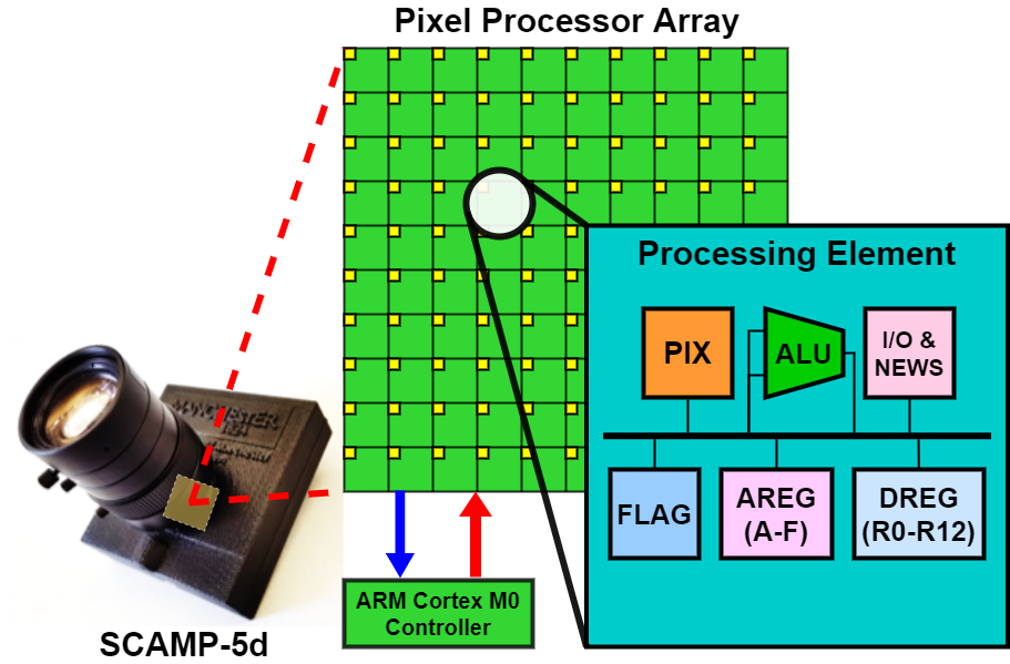
The Scamp vision system [1, 2, 4] (Figure 1) is a general-purpose visual device with parallel in-sensor computing capabilities enabled by novel large-scale circuit design and system integration of photosensitive pixels, registers, arithmetic units, and IO. With these features, it is increasingly integrated with robots for various applications with low-power consumption, and efficient parallel computing without external hardware. However, it is often inefficient to validate ideas and perform experiments when integrating the Scamp vision system with a mobile robot. Although an earlier semi-simulated platform is developed, the real Scamp vision system is not always accessible. Hence, authors are motivated to develop a fully-simulated platform consisting of the Scamp vision system and robot simulator for both researchers and novices to prototype ideas more efficiently and flexibly. The comparison of different platforms is shown in Table 1.
With this in mind, this work takes advantage of a comprehensive robot simulator CoppeliaSim [8] with Scamp vision simulator, to validate ideas and develop prototype more quickly. CoppeliaSim is a virtual robot platform where each agent can be controlled via remote API [3], hence enabling sensor readings and control instructions transferred to/from other platforms. This work developed a Python-based interface & API connecting two simulation platforms allowing data transferred mutually. In addition, through the proposed platform, we demonstrate a mobile robot navigation system based on monocular on-sensor computing with the Scamp. We made our developed platform and algorithms available from111https://github.com/Neo-manchester/fully_simulated_platform_ScampSim_Coppelia.git. The experimental video can be seen from222https://youtu.be/Ly5oBufGPag.
Earlier work on the platform development of Scamp vision system mainly include Chen et al. [2] where the whole development framework was proposed, Liu et al. [6] introduced a semi-simulated platform by integrating a real Scamp5d vision system with CoppeliaSim robot simulator for more user-friendly robot-related application development. Based on these two works, this paper developed a fully-simulated development platform for more flexible idea validation before mounting a real Scamp upon a mobile platform. Table 1 compares these three platforms where different levels of simulation and its features are shown.
| Platform | configuration | Flexibility | Developing cycle |
|---|---|---|---|
| Real Scamp vision system [2] | SCAMP + A mobile platform | Low | Long |
| Semi-sim platform [6] | SCAMP + A robot simulator | Medium | Medium |
| Fully-sim platform (this work) | SCAMP simulator + A robot simulator | High | Short |
2 Simulation Platform Development
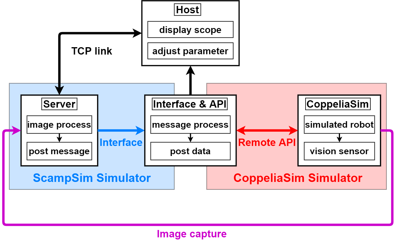
The framework of the fully-simulated system is shown in Figure 2, which mainly consists of ScampSim, CoppeliaSim, Interface & API, and Host.
2.1 SCAMP-5d Vision System Simulator
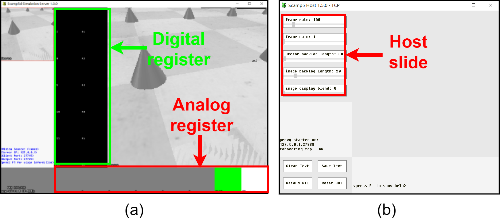
As shown in Figure 2, the ScampSim simulator usually consists of Server and communication interface with other modules. The Server can visualise the image processing and the Host provides a GUI for users to adjust image processing parameters (Figure 3). The CoppeliaSim serves as a comprehensive robot simulator where customised robot-related applications, such as vision sensors, can be set. Then, sensor readings can be transferred to the ScampSim Server for image processing. After that, the processed data are sent back through Interface & API to the robot simulator guiding the robots performing tasks. Here, the Interface & API acts as a ’bridge’ to connect the other two modules for data transmission. The detail of the SCAMP-5d vision simulation and setup can be seen from 333https://scamp.gitlab.io/scamp5d_doc/_p_a_g_e__s_i_m_u_l_a_t_i_o_n.html and [2].
2.2 CoppeliaSim Robot Simulation Environment
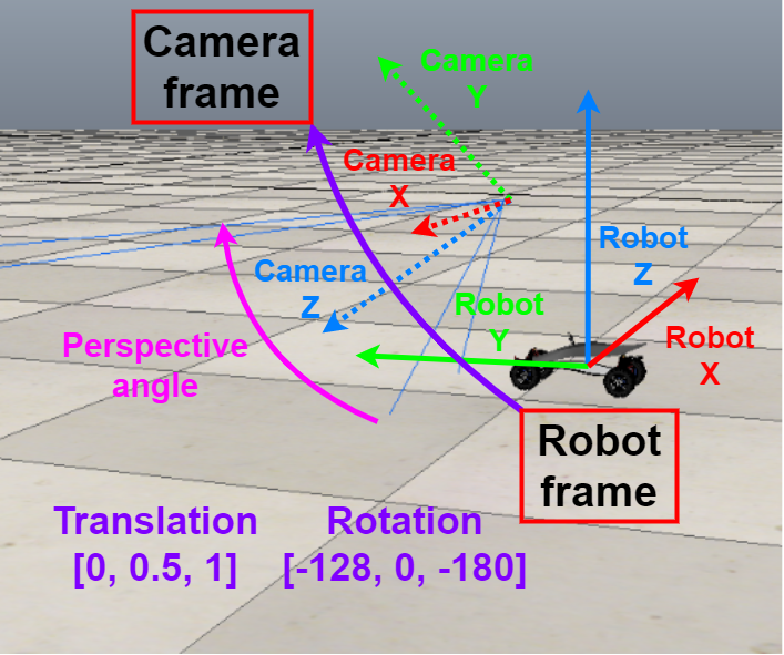
The CoppeliaSim444https://www.coppeliarobotics.com/ [8] is a popular robot simulator where the many types of mobile platforms and ambient environments are supported. By mounting a vision sensor and adjusting the associated parameters onto a Manta mobile robot, the camera can simulate a real Scamp5d camera for the gray-scale image of 256 256 capturing (Figure 4).
2.3 The Interface & Remote API
The Python-based interface is introduced to receive the messages from the ScampSim Server which is similar to the earlier simulated platform [6]. In addition, the interface integrates the remote API to communicate with the CoppeliaSim, which enabled by several CoppeliaSim API functions, such as ’’ and ’’. These functions can read and set states of agents within CoppeliaSim according to the instructions from Server through Interfaces & API.
3 Experiment
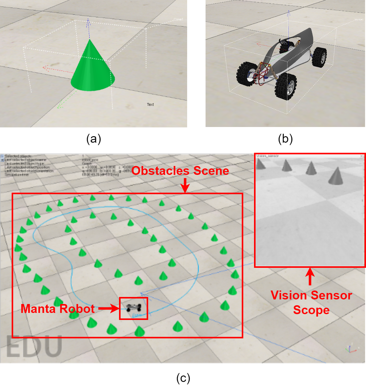
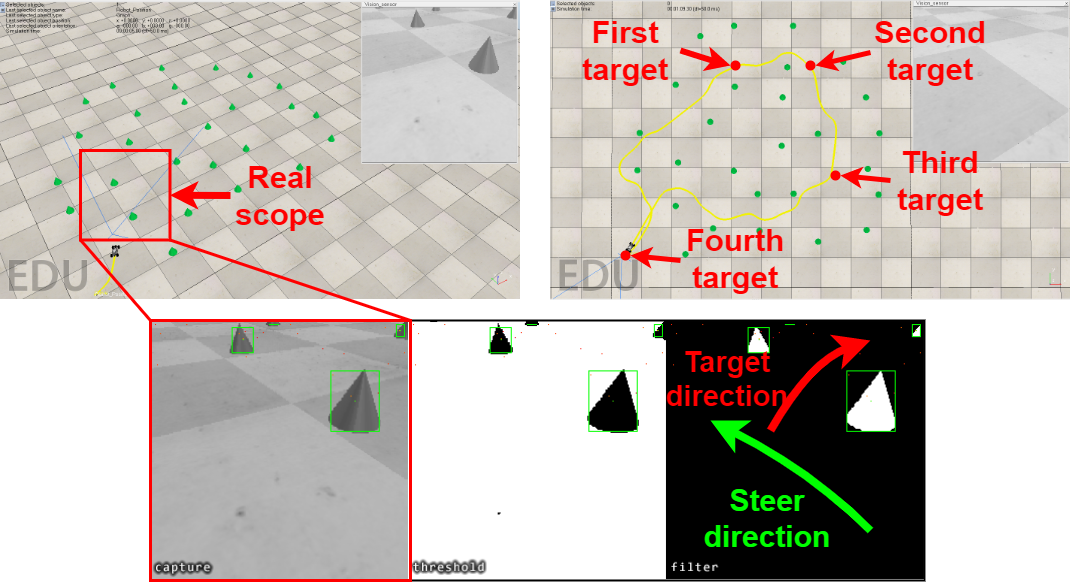
To validate the effectiveness of the proposed simulated platform, this paper set up a simple environment for the robot navigation testing the whole loop of the image capturing, data transmission, image processing, and robot control. As shown in Figure 5, the cone as the obstacles can provide features such as corner points, sloped edges and round bottom. With this setup, the simulation environment can be simplified to verify the effectiveness of the system more efficiently. The Manta robot is selected in this case, a wheeled mobile robot based on the Ackerman chassis. Users can take advantage of our platform for idea validation by setting up the more complex environment.
3.1 Robot Navigation Algorithm
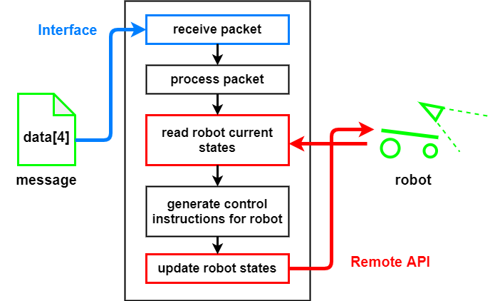
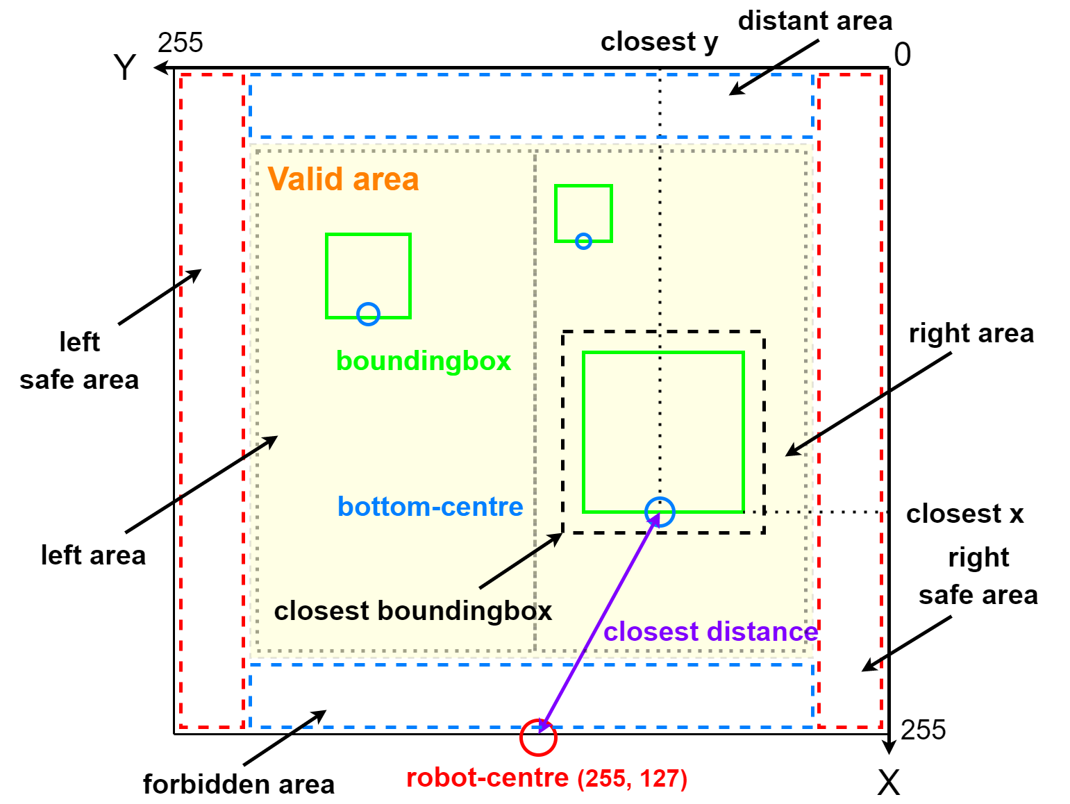
This section proposes algorithms for the robot obstacle avoidance and navigation to the pre-set targets, which can be seen in Figure 6 and Algorithm 1 in detail. ’’ is the message from the Server containing robot navigation and obstacle avoidance related information: ’’, ’’, ’’ and ’’ (Figure 9). is the safe range to avoid the collision. The obstacle avoidance manoeuvre should be performed once the distance between the vehicle and barriers is detected to be smaller than the . The target is achieved successfully when the distance between the vehicle and the target is smaller than the .
Input:
data[4], target // Server message and pre-set targets
Output:
// control the robot steer angle
3.2 Image Processing Algorithm
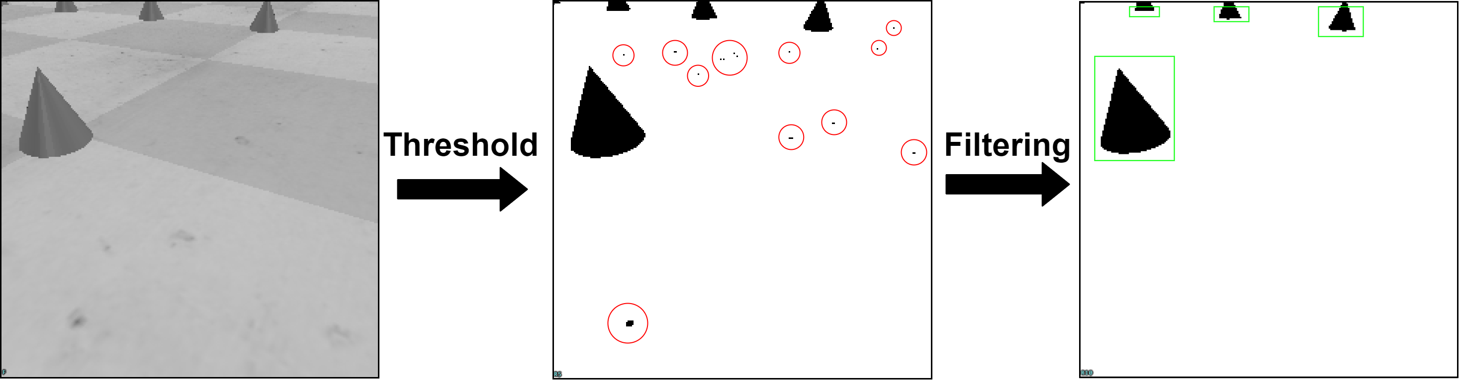
The ScampSim Server performs image processing algorithms in the same parallel way with the real Scamp vision system once the sensor reading image is received from the CoppeliaSim. As can be seen from Figure 7, binary thresholding and noise filtering are the main image preprocess methods to efficiently segment obstacles out with a clean background for further image processing.
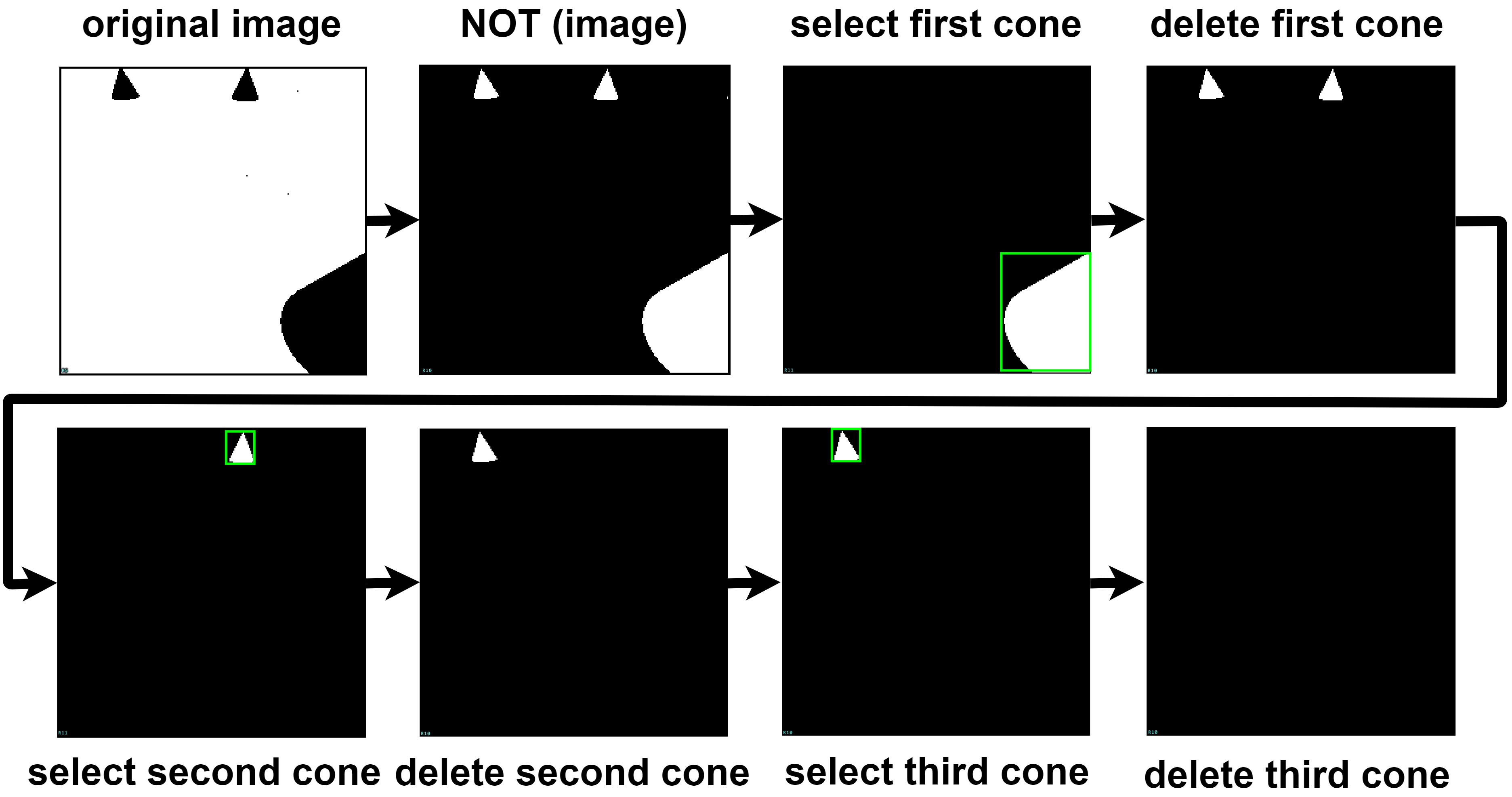
Then, this work takes advantage of the Scamp built-in flooding function () to efficiently obtain the bounding box (’’) of each cone, hence to get the approximate size information of each obstacle with the thinking of a bigger bounding box indicating a shorter distance. The obstacle avoidance starts from the closest one. Details can be seen from Algorithm 2, Figure 8 and Figure 9.
Once cones are segmented, the first ’1’ pixel can be the source to apply the flooding operation to get rid of other cones. The boundingbox function is performed to get the size of this cone (Figure 8). Then, the found cone should be deleted from the original image to start the next iteration of cone detection until all the cones are extracted.
Input: R10 // image after threshold and filtering
Output: data[4] // post message
3.3 Robot Obstacle Avoidance Algorithm
If no barriers are detected, the robot will follow the target navigation algorithm shown in Algorithm 1. Once obstacle distances are smaller than , the obstacle avoidance functions are activated shown in Equation 1 and 2.
| (1) |
| (2) |
The and represent the closest obstacle’s distance and direction in message data[4]. A closer cone produces a bigger . The and are adjustable parameters related to the safe range length and steering response sensitivity respectively. The negative sign in Equation 2 means the robot turns towards the direction far from the closest obstacle.
3.4 Navigation Experiments
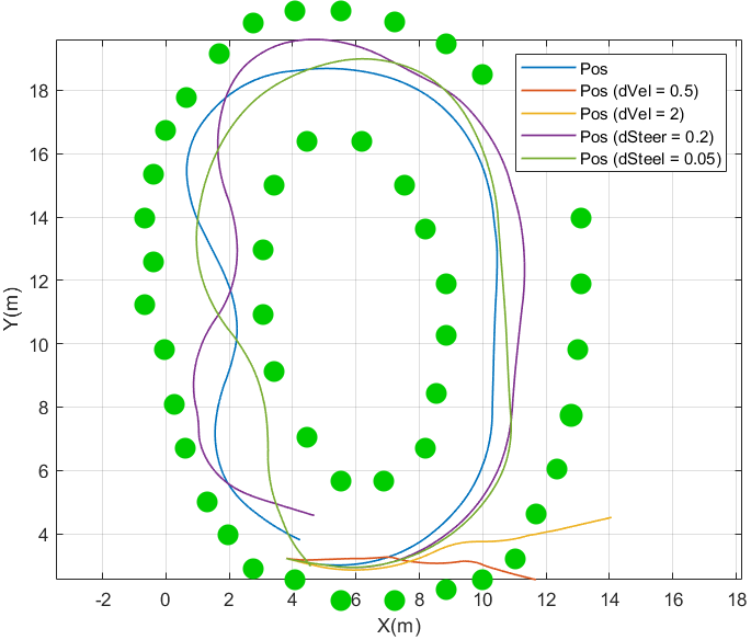
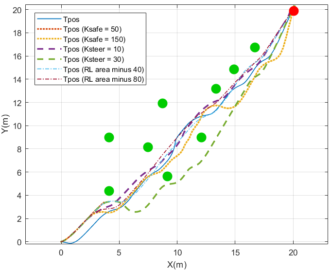
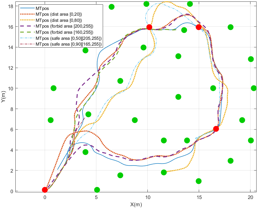
This section presents three navigation tasks, reactive navigation [5], single target, and multiple targets navigation, to verify the fully-simulated environment and the above-mentioned algorithms. The initial parameters for the experiment setup are shown in Table 2. For the reactive navigation, the robot navigates freely to prevent collisions in the environment with an obstacle layout of concentric-like ellipses as shown in Figure 10 where the multiple trajectories can be seen. Then single and multiple tasks navigation are illustrated. In this case, the robot not only performs obstacle avoidance but also path planning towards its target position through obstacles (Figure 11,Figure 12 and Figure 13).
| Parameter ID | Initial Value |
|---|---|
| dVel | 1(r/s) |
| dSteer | 0.1(rad) |
| 100 | |
| 20 | |
| 200 | |
| 1 | |
| distant area | [0,50] |
| forbidden area | [240,255] |
| safe area | [0,10],[245,255] |
| right and left area | [15,127],[128,240] |
4 Conclusion and Future Work
A fully-simulated environment integrating a Scamp simulator and CoppeliaSim is presented in this work providing researchers with a flexible idea and prototype validation platform. In the experiment, we use reactive navigation, single task and multi-task navigation to validate the effectiveness of the proposed platform. Customised environments and mobile platforms can be built based on our proposed platform by users according to different types of applications.
However, a more effective synchronisation mechanism should be optimised to decrease the influence of communication latency among these three modules. In addition, the Interface & remote API module can be improved along with the updates of Interface libraries for the Scamp vision system in the future.
References
- [1] Stephen J Carey, Alexey Lopich, David RW Barr, Bin Wang, and Piotr Dudek. A 100,000 fps vision sensor with embedded 535gops/w 256 256 simd processor array. In 2013 Symposium on VLSI Circuits, pages C182–C183. IEEE, 2013.
- [2] Jianing Chen, Stephen J Carey, and Piotr Dudek. Scamp5d vision system and development framework. In Proceedings of the 12th International Conference on Distributed Smart Cameras, pages 1–2, 2018.
- [3] Stephen James, Marc Freese, and Andrew J Davison. Pyrep: Bringing v-rep to deep robot learning. arXiv preprint arXiv:1906.11176, 2019.
- [4] Yanan Liu, Laurie Bose, Jianing Chen, Stephen J Carey, Piotr Dudek, and Walterio Mayol-Cuevas. High-speed light-weight cnn inference via strided convolutions on a pixel processor array. In The 31st British Machine Vision Conference (BMVC 2020), 2020.
- [5] Yanan Liu, Laurie Bose, Colin Greatwood, Jianing Chen, Rui Fan, Thomas Richardson, Stephen J. Carey, Piotr Dudek, and Walterio Mayol-Cuevas. Agile reactive navigation for a non-holonomic mobile robot using a pixel processor array. IET Image Processing, 15(9):1883–1892, 2021.
- [6] Yanan Liu, Jianing Chen, Laurie Bose, Piotr Dudek, and Walterio Mayol-Cuevas. Bringing a robot simulator to the scamp vision system. arXiv preprint arXiv:2105.10479, 2021.
- [7] Yanan Liu, Jianing Chen, Laurie Bose, Piotr Dudek, and Walterio Mayol-Cuevas. Direct servo control from in-sensor cnn inference with a pixel processor array. arXiv preprint arXiv:2106.07561, 2021.
- [8] Eric Rohmer, Surya PN Singh, and Marc Freese. V-rep: A versatile and scalable robot simulation framework. In 2013 IEEE/RSJ International Conference on Intelligent Robots and Systems, pages 1321–1326. IEEE, 2013.