DQN-based Beamforming for Uplink mmWave Cellular-Connected UAVs
Abstract
Unmanned aerial vehicles (UAVs) are the emerging vital components of millimeter wave (mmWave) wireless systems. Accurate beam alignment is essential for efficient beam based mmWave communications of UAVs with base stations (BSs). Conventional beam sweeping approaches often have large overhead due to the high mobility and autonomous operation of UAVs. Learning-based approaches greatly reduce the overhead by leveraging UAV data, like position to identify optimal beam directions. In this paper, we propose a reinforcement learning (RL)-based framework for UAV-BS beam alignment using deep Q-Network (DQN) in a mmWave setting. We consider uplink communications where the UAV hovers around 5G new radio (NR) BS coverage area, with varying channel conditions. The proposed learning framework uses the location information to maximize data rate through the optimal beam-pairs efficiently, upon every communication request from UAV inside the multi-location environment. We compare our proposed framework against Multi-Armed Bandit (MAB) learning-based approach and the traditional exhaustive approach, respectively and also analyse the training performance of DQN-based beam alignment over different coverage area requirements and channel conditions. Our results show that the proposed DQN-based beam alignment converge faster and generic for different environmental conditions. The framework can also learn optimal beam alignment comparable to the exhaustive approach in an online manner under real-time conditions.
Index Terms:
5G, mmWave, Beam alignment, Deep Q-NetworkI Introduction
Unmanned aerial vehicles (UAVs) are envisioned as the vital ingredients for future wireless systems using millimeter wave (mmWave). Especially, the deployment of cellular-enabled UAV- user equipment (UE)s (hereafter addressed as UAVs) adds unique features pertaining to high mobility and autonomous operations to a myriad of civil applications, such as traffic surveillance, mineral exploration, internet drone delivery systems, etc.[1]. The mmWave frequencies with multiple input multiple output (MIMO) beamforming and line-of-sight (LoS) dominant connectivity enable high-speed data access for unmanned aerial vehicle (UAV)s and also possess challenges such as reliability and low-latency communication besides interference during aerial-ground communications. Solving these challenges is also essential for efficient control of UAVs in fifth generation (5G) and beyond communications. It is noted that more flexible three-dimensional (3D) beamforming will be deployed in the forthcoming 5G systems, to enhance both beamforming gain and interference mitigation by exploiting the angle resolutions in both azimuth and elevation dimensions of UAVs in the sky[2]. UAVs for aerial-terrestrial interference management has been extensively studied in base station (BS)-UAV communication scenario over recent years[3, 4]. Hence, mmWave beam alignment is critical in supporting the flying UAVs with high mobility and semi-autonomous operations.
Fast mmWave beam alignment can enhance the data throughput for both UAV-UAV and BS-UAV communications under 5G and beyond wireless systems. Especially, the availability of UAV position information at lower frequencies (following the 3rd generation partnership project (3GPP) standard [5]) may also provide scope for reliable communication in addition to increasing throughput. Position information for fast beam alignment has been recently studied under vehicular context in mmWave systems [6, 7]. On the other hand, high mobility and autonomous operation of UAVs will require frequent beam realignment as well. Therefore, a faster and reliable beam alignment using UAV position information is crucial in enabling high data rate for mmWave UAVs.
Existing works [8, 9] proposed beam tracking schemes using Kalman filters with high processing complexity. However, these schemes are vulnerable to abrupt changes in environment when UAVs are moving at high speeds and tracking error accumulates over time. On the other hand, conventional beam sweeping solutions [10] often have large overhead, which is also unacceptable with respect to high speed and autonomous movement of UAVs as it requires frequent beam re-alignment. An alternate approach to this is to perform fast beam alignment for every change in UAV position along the BS coverage area. Existing works in vehicular environment proposed different beam alignment approaches for terrestrial systems based on black box function optimization[11, 12] and the use of contextual information [7, 13].
Contextual information generally involves data from the sensors such as position information, antenna configurations, received signal strength (RSS) power etc. using low frequency control signals from 3GPP[14] whenever needed, as this information is used abundantly to reduce the beam training overhead. The authors in [13] assumed position information as context and perform beam training over selected subset of beam-pairs by updating a database of channel strength information in an online manner. The proposed method suits well to the vehicular communication context with rapid channel variations in the environment. BS-UAV environment generally involves large coverage areas and high speed mobility of UAVs resulting in frequent change in UAV position. As a result, pre-processing of beam pairs and maintaining a database could be complex, non-generic and also cause significant overhead. In addition, learning a subset of beam-pairs based on the past beam measurements might not be essential as there are relatively less channel variations under this environment.
Black box optimization frameworks in [15, 16], investigate application of supervised machine learning (ML) techniques to beam alignment problem. These frameworks are computationally efficient but assumed a separate training data collection phase for proposed supervised learning environments.
In our work, we propose a generic deep Q-network (DQN)-based framework using both black box and user-context optimization techniques, in an attempt to progress from the previous works for UAV beam alignment problem. We approximate the beam alignment optimization problem for a multi-location environment using neural networks (NN) techniques and learn best beam-pairs for any UAV in these locations from their past beam measurements. This approximation also helps in using prior knowledge of the propagation environment to significantly reduce the beam-alignment overhead. Our algorithm takes into account UAV location and finds an optimal beam pair to maximize the beamforming gain between BS and UAV. To identify the significant change in UAV location, we consider a grid environment with UAV position information of the grid element as the user-context information. The main contribution of this paper is that we propose the reinforcement learning (RL)-based DQN framework to optimize beam alignment between BS and UAV for any grid position inside the BS coverage area, during uplink mmWave communication. We benchmark our results against multi-armed bandit (MAB), exhaustive based approaches, and analyse against different coverage area requirements under ideal urban macro-cellular (UMa)- non-line of sight (nLoS) conditions. We also simulate the better training performance of DQN framework generic to any UAV position in an online manner under varying channel conditions.
The rest of the paper is organized as follows. Section II presents the problem formulation and communication modelling, considered in this problem. Section III discuss in detail about the proposed DQN based RL approach for beam alignment. Section IV presents the comparison of the proposed DQN-based RL approach against MAB-based learning and different coverage area requirements under ideal channel conditions. The section also discuss about the online learning of DQN and its analysis under varying channel conditions. Section VI summarizes the conclusion and future work.
II System and Communication Model
In this section, we describe the system model, communication model for the learning framework using 3GPP protocol standards and also formulate the parameters to be used in the proposed learning framework. The objective of this problem is to maximize the beamforming between BS and the UAV to provide efficient communication under the defined environment and channel conditions.
II-A System Model
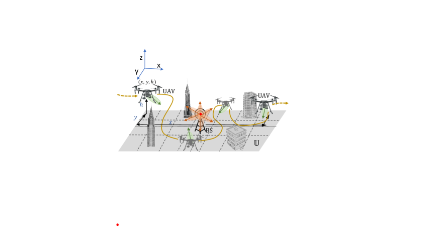
We consider a cellular mmWave MIMO uplink communications between a single UAV and a single BS under UMa environments. The BS is fixed at and communicates with the moving UAV (hereafter used as UE) using a multi-path mmWave beamforming as shown in Figure 1. The multi-antenna UE hovers randomly and communicates with the multi-antenna BS in the urban environment following 5G new radio (NR) standard protocol[14]. We consider an analog beamforming equipped with one radio frequency (RF) chain and uniform linear array (ULA) structures of and antennas for both BS and UE, respectively. The UE transmits (TX) while the BS receives (RX) a radio signal in multiple beam directions following and codebook, respectively with angles defined as
| (1) |
where represents a RF radio beam direction with a fixed narrow beam width (), represents , antennas for and codebook, respectively. The codebook values are defined using the beamforming vectors and for UE and BS, respectively, given by , where , , and , for and , respectively. Here, is the antenna spacing, is the wavelength and is the codebook direction (1). The UE moves randomly along the 3D coverage area which is divided into multiple grids of equal size, the set enclosing them is denoted as . The received signal measurement can be observed at the BS for different TX-RX beam direction pairs and their timing information can be estimated using subframe structure (SS) block symbols, during beam selection procedure of the 3GPP beam-alignment protocol[14]. For simplicity, we define the time consumed by each such symbol as the travel time unit (TTU), to measure the communication overhead of the learning procedure.
II-B Communication Model
For the communication model, we consider a multi-path link (LoS or nLoS) radio channel between UE at time and BS location . represents the UE position on grid index in the BS coverage area at any time instant , given by
| (2) |
where . We assume (with respect to BS locations) is known during each procedure of 3GPP beam access protocol. Let , be the angle of departure (AoD) and angle of arrival (AoA) of communication link between BS and UE, respectively. The UE transmits radio signals in a codebook direction from while the BS receives the signal through one of its multiple beam directions following (1). Baseband equivalent of the received signal is given by
| (3) |
where is transmission power, is the number of multi-paths or reflection points in the UMa environment [17], , , are the antenna channel gain and array response vectors for and along the communication link, respectively. Here, , where and for and , respectively. , are the transmit and receive unit-norm beamforming vectors, is the effective noise with zero mean and two-sided power spectral density , represents one orthogonal frequency division multiple access (OFDM) symbol of the time-domain transmitted signal with bandwidth and TTU time period with . Here, is the number of samples spanned over TTU time. In this work, we assume the channel measurements of the multi-path link to follow 3GPP UMa channel conditions[17]. We define . Then, the signal-to-noise ratio (SNR) is given as and overall rate measurement in bits per channel use is given by
| (4) |
Thus, the beam alignment for the above formulation is realized through data rate measurements. The optimal beam-pair for UE-BS is selected based on their data rates under the scenario mentioned in Section II-A.
II-C Problem Formulation
We consider an uplink communication between BS and UE following 3GPP beam access protocol [18, 14]. The beamforming protocol in general involves mainly three procedures, Initial communication (used as procedure), beam selection (used as procedure) and beam refinement (used as procedure) [18]. Here, we assume UE and BS share position information and sequence of beam-pairs with one another at low frequencies during , respectively and sweep the selected sequence of beam pairs during following 5G communication [14]. We formulate the 3GPP based beam-pair alignment learning through and procedures, and maximize the beamforming gain for any UE position around the BS coverage area . Timing information of these procedures assumes 3GPP frame structure and time for each OFDM slot is defined in our work as the TTU[18]. We consider RSS of radio signal and radio beam pair directions (both TX and RX) as the known and unknown parameters of this multi-location environment, respectively. We define the state and action spaces for learning based beam-pair alignment as follows:
| (5) | ||||
where is the location of UE within coverage area (2) while , is the beam codebook sets at UE and BS side respectively (1).
RL is an interactive learning problem following a markov decision process (MDP). In this work, the RL-based beam alignment problem is modelled as a partially observable Markov decision process (POMDP). At any time instant , we define the parameters , and where , , are the state, action and reward at time instant . corresponds to the set of previous actions applied for state transitions until the time instant . Data rate measurements computed on applying each action are considered as the rewards for the problem. We denote as the observed history of all such state information and past actions. After the 3GPP initial communication procedure with UE, BS starts with a random receiving beam direction and then proceeds towards the maximum beamforming gain by applying actions and undergoing state transitions, accordingly. The current applied action becomes part of the next state, undergoing state transition. The objective of this problem can be formulated as
| (6) | ||||
where is the optimal data rate measurement observed among the information history until time instant , and are the rewards and data rate measurement observed on applying action beam-pair , respectively. We follow DQN approach to solve this RL objective problem.
III Implementation
DQN is a value-based approach used generally in the context of RL [19]. The approach learns an optimal approximated policy of states mapping to actions by parameterizing and estimating state-action value function using deep neural networks (DNN). We denote the primary DNN network weight matrix and target DNN network weight matrix as and , respectively [19]. We consider a fully connected DNN for both the networks where is updated with primary network parameters , after every iterations. The input of DNN is given by the variables in . The intermediate layers are fully connected linear units with rectifier linear units (ReLU) by using the function and the output layer is composed of linear units, which are in one-one corresponding relationship with the action space . We consider initialization of bias and weights of these layers with zeros and Kaiming normalization, respectively.
At a time instant , DQN selects action and perform forward propagation of following -greedy policy. A memory buffer of experiences , are collected, where a mini batch of them are randomly sampled and sent into DQN [19]. During back propagation, a mean squared error (MSE) loss function is computed between primary, target networks and is updated using stocastic gradient descent (SGD) and Adam Optimizer as
| (7) |
where is the learning rate, is the gradient of the DQN loss function. Complete steps followed by DQN for RL based beam alignment problem are shown in Algorithm 1. Here, we define episode as the consecutive set of actions applied on the starting state until it reaches the terminal state with maximum beamforming gain for that location. In order to prevent episodes with infinite set of actions during training, we confine maximum episode length to exhaustive set of beam pairs possible under the chosen antenna configuration.
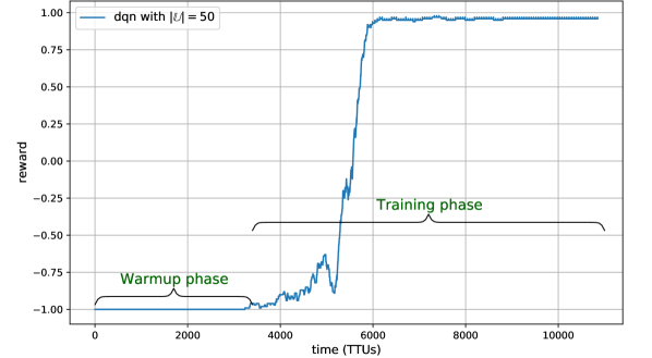
As the RL learning objective formulation involves both current data rate and best observed data rate measurements (shown in (6)), we consider the overall online training procedure of DQN framework under two phases namely, Warmup phase and Training phase as shown in Fig. 2. During the Warmup phase, the exploration is set to maximum, in order to observe the best possible data rate for the given UE location by applying maximum episode length of actions. During the Training phase, the algorithm continues to reduce its exploration and move towards exploitation following -greedy policy. The episode starts with initial action corresponding to and applies next actions to reach the terminal state as quickly as possible. The Warmup phase results in extra training time at the start but favours quick convergence of DQN during training phase resulting in faster beam-alignment training for the multi-location environment.
IV Simulation results
As described in Section III, we implement the RL-based beam alignment using DQN, following objective (6) and steps mentioned in Algorithm 1. Similarly, we implement the MAB-based approach for our problem (following existing works [13, 20]) using greedy upper confidence bound (gUCB) algorithm. Traditional approach mainly involves exhaustive search over entire action space , to find the best beam pair with maximum beamforming gain between UE and BS. In our work, the exhaustive approach in general causes significant communication overhead () with higher antenna elements as frequent beam scanning is required for every change in grid element unit of UE inside . On the other hand, RL and MAB learning-based methods once converged, can significantly reduce the communication overhead during procedure and maximize beamforming gain in time.
In this section, we first investigate the training performance of our proposed RL-based approach against MAB-based learning and different coverage area requirements in order to maximize beam alignment under ideal UMa-nLoS channel conditions. Later, we combine these observations and perform online beam alignment in the presence of channel variation conditions.
IV-A DQN training performance
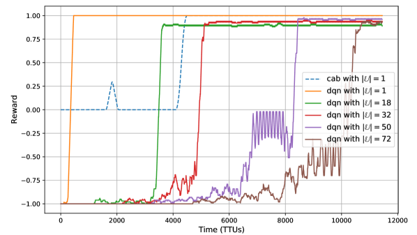
As shown in Fig. 3, brown and blue plots represent the accumulated rewards over time for DQN and gUCB, respectively, under single UE grid location () and ideal UMa-nLoS channel conditions with 6 reflection points. Our results show that the DQN-based approach quickly accumulate the rewards over TTU time for learning the optimal beam pair. The gUCB approach involves iterating over exhaustive action space , thus consuming more time at every episode of its training procedure. On the other hand, DQN uses its warmup phase to quickly determine the best possible data rate measurement for the current state and then learn the determined best rate during training phase, by applying actions in a iterative manner. With increase in BS coverage area, the gUCB-based approach is observed to be unreliable for multiple grid locations without frequent re-training. This is due to substantial change in RSS measurements w.r.t (TX,RX) beam pairs for every UE grid location.
On the other hand, DQN agent with the same architecture is very much reliable to learn beam alignment across multiple UE locations for different coverage area requirements under the same ideal channel conditions as shown in Figure 3. After the convergence is obtained, BS can quickly align using learnt optimal beams for any UE position within the coverage area without any re-training. Also, the learning is observed to be relatively quicker in convergence with increase in coverage area of BS. With increase in coverage area, neighbouring grid elements with similar optimal beam pairs converge DQN faster as part of its MDP process, resulting in average less number of training iterations per grid element alongside convergence. Thus, the DQN agent can achieve faster and reliable beam alignment due to its training procedure and the neighbourhood grid element convergence.
IV-B online DQN performance with channel variation and shadow fading
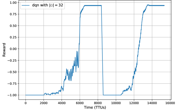
In this subsection, we plot DQN training performance in real-time conditions in an online manner by considering change in channel conditions, thermal noise, slow fading and slow channel variation at UE grid locations as shown in Fig. 4.
| \rowcolorcyan Parameters | Value |
|---|---|
| mmWave Channel | UMa |
| mmWave freq | GHz |
| carrier spacing freq | kHz |
| antenna element spacing | |
| Transmit power | dBm |
| Transmit antenna elements | 8 |
| Receiving antenna elements | 8 |
| Noise Level | -174 dBm |
| BS location | |
| coverage xloc | m |
| coverage yloc | m |
| coverage zloc | m |
| Cardinality of State Space | |
| Cardinality of Action Space |
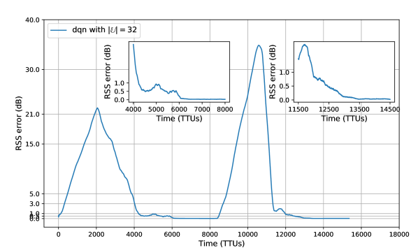
Fig. 4(a) and Fig. 4(b) plot the rewards and RSS error of the DQN learning agent, respectively. We define RSS error as the expectation of the difference between DQN-agent and exhaustive approach RSS errors over BS coverage area. For these simulations, we consider a () coverage area environment between BS and UE. The environment is equipped with thermal noise, shadow fading, UMa-nLoS to UMa-LoS channel conditions along with a slow rician channel variation. The parameters used for this simulation are disclosed under Table. I. Depending on the defined coverage area, different path loss models including the aerial view of UE for both UMa-nLoS and UMa-LoS are included following 3GPP[17]. It is noted here that same set of hyper-parameters are used throughout the DQN simulation. We observe that DQN agent performs similar to previous results, converging well under both varying channel conditions. The disturbance in the smoothness of the reward plots observed in Fig. 4(a) could be due to the impact of channel variation under nLoS conditions. From Fig. 4(b), we observe that the RSS error increases at first during online training phase and then decreases to zero on model convergence under both varying LoS and nLoS conditions. This shows that DQN-framework on convergence, achieves optimal data rate measurements similar to that of exhaustive approach.
V Acknowledgements
The research was supported by 6G Flagship programme, Finland and the Engineering and Physical Research Council (EPSRC), U.K., under Grant EP/W004348/1.
VI Conclusion and Future Work
In this paper, we developed a learning-based beam alignment framework for mmWave MIMO uplink BS-UAV communication. We proposed a RL-based framework using DQN to maximize the beam alignment for any UAV position within the BS coverage area following 3GPP standard. We also analyze the same DQN architecture over different coverage requirements under ideal channel conditions to demonstrate the generalization of the proposed RL-based framework for beam learning. Our results show that, the proposed approach significantly outperforms the training performance of the MAB-based method and also learns optimal beam pairs comparable to that of the heuristic method in an online manner under varying channel conditions. Having shown some promising results, we will address the full capabilities of these generic learning architectures under higher MIMO antenna configurations, large number of beam-directional pairs, interference mitigation etc. in future.
References
- [1] L. Zhang, H. Zhao, S. Hou, Z. Zhao, H. Xu, X. Wu, Q. Wu, and R. Zhang, “A Survey on 5G Millimeter Wave Communications for UAV-Assisted Wireless Networks,” IEEE Access, vol. 7, pp. 117 460–117 504, July 2019.
- [2] Y. Zeng, J. Lyu, and R. Zhang, “Cellular-connected uav: Potential, challenges, and promising technologies,” IEEE Wireless Communications, vol. 26, no. 1, pp. 120–127, September 2018.
- [3] X. Lin, V. Yajnanarayana, S. D. Muruganathan, S. Gao, H. Asplund, H.-L. Maattanen, M. Bergstrom, S. Euler, and Y.-P. E. Wang, “The sky is not the limit: Lte for unmanned aerial vehicles,” IEEE Communications Magazine, vol. 56, no. 4, pp. 204–210, April 2018.
- [4] M. M. Azari, F. Rosas, A. Chiumento, and S. Pollin, “Coexistence of terrestrial and aerial users in cellular networks,” in 2017 IEEE Globecom Workshops (GC Wkshps). IEEE, Dec 2017, pp. 1–6.
- [5] E. T. S. Institute, “LTE; Evolved Universal Terrestrial Radio Access (E-UTRA); Radio Resource Control (RRC); Protcol Specification, Technical Report 36.331, version 15.10.0, Release 15,” European Telecommunications Standards Institute, July, 2020.
- [6] F. Devoti, I. Filippini, and A. Capone, “Facing the millimeter-wave cell discovery challenge in 5g networks with context-awareness,” IEEE Access, vol. 4, pp. 8019–8034, Nov 2016.
- [7] J. C. Aviles and A. Kouki, “Position-aided mm-wave beam training under nlos conditions,” IEEE Access, vol. 4, pp. 8703–8714, Nov 2016.
- [8] J. Zhao, F. Gao, W. Jia, S. Zhang, S. Jin, and H. Lin, “Angle domain hybrid precoding and channel tracking for millimeter wave massive mimo systems,” IEEE Transactions on Wireless Communications, vol. 16, no. 10, pp. 6868–6880, Aug 2017.
- [9] J. Zhao, F. Gao, L. Kuang, Q. Wu, and W. Jia, “Channel tracking with flight control system for uav mmwave mimo communications,” IEEE Communications Letters, vol. 22, no. 6, pp. 1224–1227, April 2018.
- [10] J. Saloranta, G. Destino, and H. Wymeersch, “Comparison of different beamtraining strategies from a rate-positioning trade-off perspective,” in 2017 European Conference on Networks and Communications (EuCNC). IEEE, June 2017, pp. 1–5.
- [11] T. Kadur, H.-L. Chiang, and G. Fettweis, “Effective beam alignment algorithm for low cost millimeter wave communication,” in 2016 IEEE 84th Vehicular Technology Conference (VTC-Fall). IEEE, Sept 2016, pp. 1–5.
- [12] P. Susarla, Y. Deng, G. Destino, J. Saloranta, T. Mahmoodi, M. Juntti, and O. Sílven, “Learning-based trajectory optimization for 5g mmwave uplink uavs,” in 2020 IEEE International Conference on Communications Workshops (ICC Workshops). IEEE, June, 2020, pp. 1–7.
- [13] V. Va, T. Shimizu, G. Bansal, and R. W. Heath, “Online Learning for Position-Aided Millimeter Wave Beam Training,” IEEE Access, vol. 7, pp. 30 507–30 526, Mar 2019.
- [14] E. Dahlman, S. Parkvall, and J. Skold, 5G NR: The next generation wireless access technology. Academic Press, 2020.
- [15] Y. Wang, N. J. Myers, N. González-Prelcic, and R. W. Heath, “Site-specific online compressive beam codebook learning in mmwave vehicular communication,” IEEE Transactions on Wireless Communications, vol. 20, no. 5, pp. 3122–3136, 2021.
- [16] C. Jiang, H. Zhang, Y. Ren, Z. Han, K.-C. Chen, and L. Hanzo, “Machine learning paradigms for next-generation wireless networks,” IEEE Wireless Communications, vol. 24, no. 2, pp. 98–105, Dec 2016.
- [17] E. T. S. Institute, “Study on Enhanced LTE support for Aerial Vehicles 36.777 version 1.0.0 Release 15,” European Telecommunications Standards Institute, Jan, 2018.
- [18] ——, “Study on 5G New Radio(NR) access Technology, Technical Report 38.912, version 15.0.0, Release 15,” European Telecommunications Standards Institute, May, 2017.
- [19] V. Mnih, K. Kavukcuoglu, D. Silver, A. A. Rusu, J. Veness, M. G. Bellemare, A. Graves, M. Riedmiller, A. K. Fidjeland, G. Ostrovski et al., “Human-level control through deep reinforcement learning,” Nature, vol. 518, no. 7540, p. 529, Feb, 2015.
- [20] M. Hashemi, A. Sabharwal, C. E. Koksal, and N. B. Shroff, “Efficient beam alignment in millimeter wave systems using contextual bandits,” in IEEE INFOCOM 2018-IEEE Conference on Computer Communications. IEEE, April, 2018, pp. 2393–2401.