Precise Beam Energy Determination for Hall A after the CEBAF 12 GeV Upgrade
Abstract
Precise and accurate measurements of the beam energy delivered to the experimental halls at the Thomas Jefferson Accelerator Facility (Jefferson Lab) is required by many experiments for proper data analysis and physics event reconstruction. During the 6 GeV era of Jefferson Lab, the energy delivered to experimental Hall A was determined to 2E-4 dE/E with multiple measurements; but after the machine was upgraded to 12 GeV, the accelerator’s beam energy calculations needed to be re-calibrated. In order to link the 6 GeV era calibrations to the 12 GeV era, the Hall A ARC energy measurement system was left unmodified. After the upgrade, this system was used to determine the absolute beam energy being delivered into Hall A and find the new calibrations for the main machine. To ensure the validity of these results, they have been cross checked using elastic scattering data as well as spin precession data.
keywords:
beam energy , ARC energy measurement , elastic scattering , spin precession1 Introduction
The Continuous Electron Beam Accelerator (CEBA) located at the Thomas Jefferson National Accelerator Facility (Jefferson Lab) started operations in the mid-1990s to provide a multi-GeV continuous-wave (CW) electrons beam to three experimental halls [1, 2]. For the experimental nuclear physic program, it was crucial to determine the absolute energy of the CEBAF beam both precisely and accurately for the absolute cross section measurements. Two dedicated systems were used to determine the energy of the beam being delivered into experimental Hall A:
- 1.
-
2.
eP: Using elastic scattering measurements with a dedicated system to precisely measure scattering angles to absolutely determine the beam energy [5].
Another way to determine the energy involved making measurements of the degree of longitudinal electron polarization at the source and in the experimental halls [6, 7, 8].
The completion of the 12 GeV upgrade at Jefferson Lab arrived with a full set of new experiments that must have a precise knowledge of the beam energy for the physics analysis. In general, Hall A requires a determination of the absolute beam energy of dE/E = 10-4. The current energy measurements is done using the Arc method [9], named after the location where the hardware is placed. It uses the section of the beamline that connects the accelerator and the Hall (the ARC). This method was first developed by the French collaboration of Pascal Vernin and the Scalay group [9], and it uses the ARC as a spectrometer to calculate the exact value of the energy. Table 1 summarizes the beam energy parameters delivered to Hall A.
| Beam Property | Nominal Value (Range) | |||||||||||||||
|---|---|---|---|---|---|---|---|---|---|---|---|---|---|---|---|---|
| Current | 1-120 A | |||||||||||||||
| Beam polarization | up to 85 | |||||||||||||||
| Energy Spread |
|
This paper describes and shows the results of the ARC energy method for the five energy passes, and the elastic energy measurement for the half pass. Then, it reviews the sources of uncertainty for each measurement and its accuracy, and finally, a comparison of the ARC and elastic measurement is done.
2 ARC Measurement Method
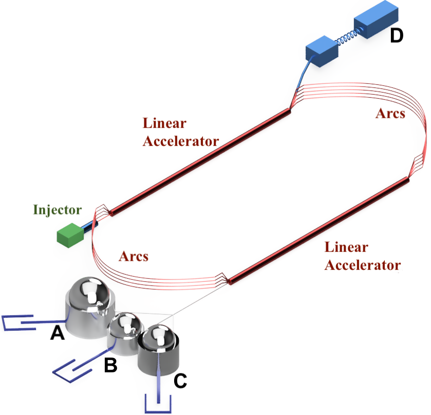
The ARC used for the energy measurement comes from the south linac and goes to Hall A, as is layout in Figure 1. It is a 40 m beam section with 9 dipole magnets, as shown in Figure 2. Eight of the magnets are used to deflect the beam, the bending angle is of approximately 34.3∘ and it has been surveyed several times during the past several years, Table 2 summarizes the results of the surveys.
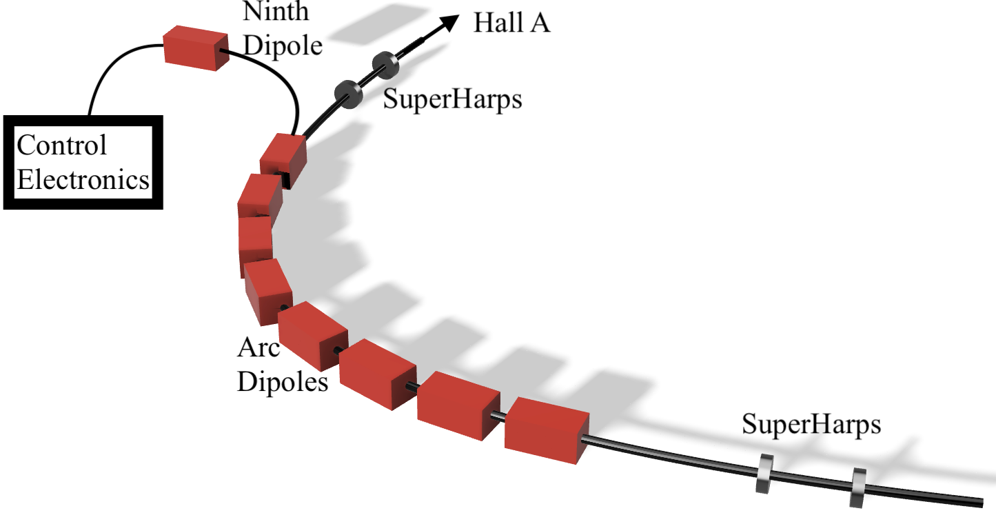
The measurement of the bending angle is done by wire scanners called SuperHarps. In practice, the wires of the SuperHarps are moved across the beam path, and when the beam hits the wire, the signal is collected by a photomultiplier tube (PMT). Based on the signal, the exact position of the beam is reconstructed. There are two SuperHarps in the ARC; one at the entrance and one at the exit of the ARC. Both are used to reconstruct the bend angle.
During the actual operation of the experiments, it is not practical to use the SuperHarps since they do an absolute but intrusive measurement. Instead, beam position monitors (BPMs) are used. A BPM consists of a cavity with four wire antennas oriented parallel to the electron beam; the radio-frequency (RF) signal from each antenna is converted into a DC signal, which is proportional to the distance between the beam and the antenna. From these four signals, the position of the beam can be determined [11]. The BPMs provide a relative measurement of the position and need regular harp scans from the SuperHarps to be calibrated and properly used.
| Surveyed Arc | Uncertainty | |
|---|---|---|
| Year | Angle (∘) | Angle (∘) |
| 1999 | 34.302 | 0.001 |
| 2001 | 34.295 | 0.001 |
| 2002 | 34.399 | 0.001 |
| 2014 | 34.259 | 0.001 |
| 2018 | 34.257 | 0.001 |
| 2021 | 34.259 | 0.001 |
The ARC measurement is based on the fact that the electron moves in a circular trajectory in a magnetic field [12]. The momentum of the electrons depends on the magnitude of the magnetic field and its bending angle,
| (1) |
where GeV rad/T-m is the speed of light, is the field integral of the dipole magnets in T-m, and is the bending angle of the beam in radians. The magnetic field is measured using the ninth dipole, which is located outside the beam line.
The energy measurement can be done either when the beam is in dispersive or achromatic mode. The dispersive mode requires the quadrupoles to be off, and the energy determination will follow Equation 1. However, quadrupoles are required for precise alignment and focus of the beam, therefore, corrections to Equation 1 have to be made. As a consequence, during production runs the quadroples are in used in an achromatic mode, and in some occasions, the quadrupoles are turned off in a dispersive mode for Energy measurements checks.
2.1 Determining ARC Field Integral
The field integral is determined by using an identical 9th dipole magnet located in a building above the beam line as shown in Fig. 3. This magnet is powered in series with the other dipoles, and is used as a reference. It is not possible to measure the field integral of the 8 dipoles in the arc as their gap is fully occupied by the vacuum pipe of the beam.
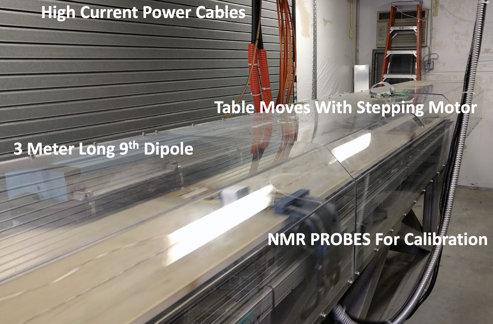
The fringe effects are accounted in the reference dipole by the use of two translating coils [9]. This pair of coils are wired in series and precisely spaced from one another. As the coils are translated through the 9th dipole’s gap, the flux through them is measured. While these coils give an extremely precise measurement, this measurement is only relative. In order to achieve an accurate absolute measurement a nuclear magnetic resonance (NMR) probe is used.
Figure 4 shows the measured ARC current against the value of the ARC field integral. The field integral was calculated by mapping the field of the ninth dipole magnet, and measuring the current running through it. It can be seen how the ARC field integral saturates at around 20 T-m where the relationship is no longer linear. These measurements are applicable in dispersive mode, and serve to provide a value of the ARC field integral based upon the measured ARC current.
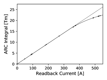
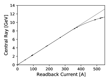
At low energies a linear fit is an accurate description, but at higher energies (and higher ARC current) a rational fit was applied.
2.2 HALLA:p and HALLA:dpp
Another measurement of the beam energy is the HALLA:p variable. In the past the variable was referred to as the “Tiefenback Energy”, named for its original creator, Michael Tiefenback. The variable currently in use is created via a method derived by Yves Roblin.
The method created by Roblin relies upon the “Electron Generation and Tracking” (ELEGANT) program [13]. ELEGANT is a Self-Describing Data Set” (SDDS) compliant program which accesses information about the accelerator from the “CEBAF Element Database” (CED). The CED is a database containing many key pieces of information such as magnet field maps [14]. This variable is built upon two parts: and HALLA:dpp. is determined using the ARC measurement method and field maps performed during the 6 GeV era. To first order, HALLA:dpp can be approximated by which is defined below to depend upon the position of the beam measured at the central beam position monitor,
| (2) |
where:
| (3) |
with k being a constant. This formula is based upon the fact that lower beam energies will be bent more in the ARC. It is important to note that these formulae are merely the first order terms of the orbit correction performed by Roblin’s calculation. There are higher order terms which make further orbit corrections. Figure 3 demonstrates that these higher order corrections amount to less than 2 MeV of the beam energy measurement. Thus, an investigation into these higher order terms is not warranted for this analysis.
The primary assumption made in the creation of the HALLA:p variable is that the value for is correct. It is important to note that HALLA:dpp depends very weakly on this value of p0. Table 4 demonstrates a discrepancy between this HALLA:p variable and ARC measurements taken by Doug Higinbotham. Since measurements made via Higinbotham’s method have shown agreement with other measurement methods in the 6 GeV era, this discrepancy must point to an issue with the HALLA:p calculation of .
3 Elastic Energy Measurement
During the E12-11-112 experiment, the accelerator was able to send half pass to Hall A by using only the North Linac, since the South Linac was explicitly turned off. The Left High Resolution Spectrometer (LHRS) was positioned with an opening angle of 17.009∘ and with a central momentum of 1.1282 GeV.
The basic components of the LHRS [15] are three superconducting quadrupoles (Q) and one superconducting dipole (D) in a QQDQ configuration. The quadrupoles align the scattered electrons while the dipole determines their momentum. The central momentum of the LHRS was calculated using NMR measurements of the magnets as given by Liyanage [16]. The momentum was chosen such that both Elastic and Quasi-Elastic peaks were accessible for the 3H and 3He gas targets. Furthermore, 1H was also available, and using these three gas targets the beam energy was measured.
The sealed gas target cells were used in a modular low pressure system as described in [17]. The length of the target was 25 cm and for the purposes of analysis only data from the center of the target 8 cm was selected, in order to avoid contamination coming from the aluminum end caps of 4 mm thick as shown in [17]. The nominal current provided for this data was of 5 A, and only events with 1.5 A were selected order to avoid any drift or trip in the beam.
After passing the magnets, the scattered electrons go through two Vertical Drift Chambers (VDCs), where the electrons ionize the gas inside the chambers, and with the information collected, the position and angle of the trajectory of the electrons are found. Then, the trigger scintillators s0 and s2m are used to record the selected candidates. Due to the high rate of the kinematics, the prescaler chosen for the trigger was 25. The Cherenkov detector filled with CO2 between the trigger scintillator planes identify the electrons with 99% efficiency and has a threshold for pions of 4.8 GeV. Finally, the preshower and shower lead glasses blocks induce a cascade of pair production and bremsstrahlung radiation from energetic particles, which are used for the measurement of the energy of the electrons. In order to select a clean sample of electrons, we require a single track in the VDC chamber, E/p 0.7, Cherenkov signal above the pion contamination (1500), an out-of-plane angle 35 mrad and an in-plane angle 30 mrad.
In the elastic scattering, the energy of the beam and the energy of the scattered electrons is related by:
| (4) |
where E is the beam energy, Ei is the energy of the scattered electrons, is the scattering angle, Eloss1 and Eloss2 are the energy losses before and after the scattering, and is the mass of the target.
Using the Equation 4 the beam energy can be calculated, if the scattering angle is the same and the scattered energy is known. Therefore, the measurement was done by selecting particles with a scattering angle of 17∘ 0.1∘. Figure 6 shows the distribution for the scattered energy after the energy loss correction.
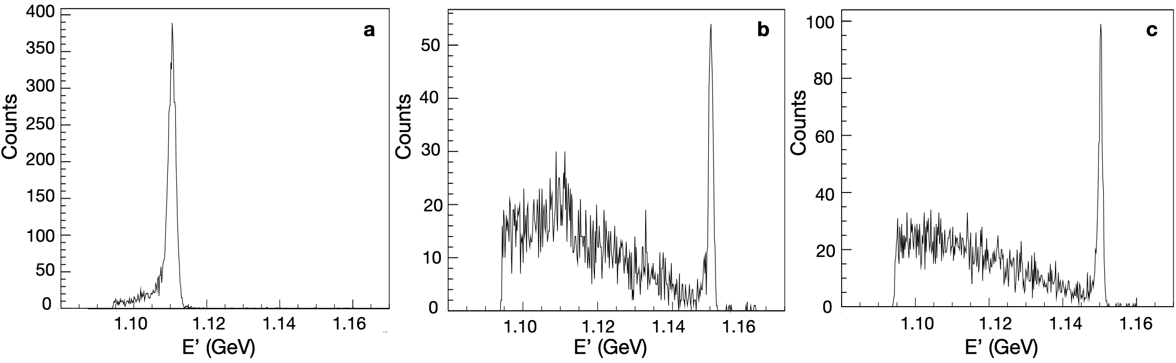
To measure the scattered energy of the electrons, a Gaussian fit was done and the results are shown in the Table 3. The scattered energy () and its uncertainty () was measured for each target.
| Target | E’(GeV) | dE’(GeV) |
|---|---|---|
| 1H | 1.1104 | 6.5x10-04 |
| 3H | 1.15029 | 7.1x10-04 |
| 3He | 1.15022 | 8.2x10-04 |
Finally, in order to account for the systematic uncertainties, several factors were studied. The summary is presented in Table 4, the LHRS central momentum represents the uncertainty given by the NMR calculation in [16] and the angle resolution represents the cut dependence of the angle chosen to measure the beam energy.
| LHRS central momentum | 4x10⁻⁴ |
|---|---|
| Angle Resolution | 8x10⁻⁵ |
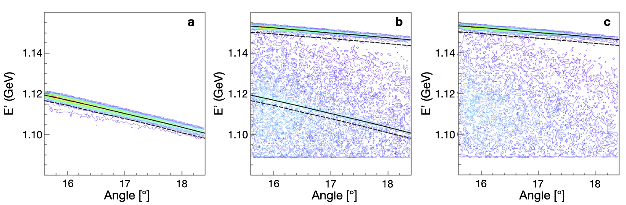
The beam energy measured using this technique is 1171.3 0.6 MeV. While the energy reported by the accelerator was of 1168 1 MeV. As a sanity check, Figure 7 shows the scattered electrons energy with respect to the scattering angle, the black and red lines correspond to the calculated E’ using the accelerator and the measured energy respectively. It shows that the measured energy reproduces the elastic data,
4 Spin Precession
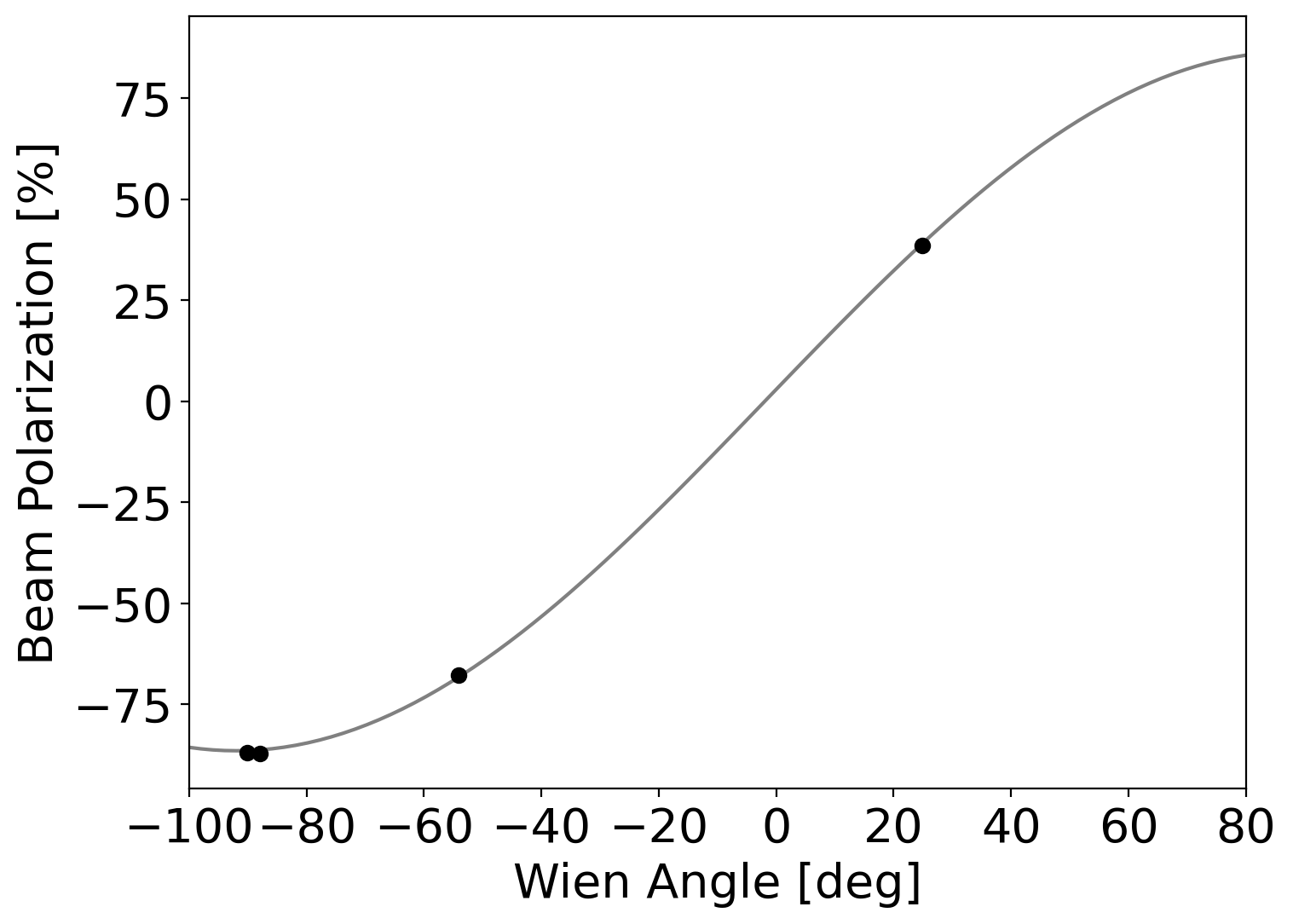
Another technique for cross checking the beam energy is to use the beam energy to make calculations of the electron spin precession from the injector to the experimental hall [7, 18]. These calculations are used to predict the Wein angle setting at the injector to provide full polarization to a hall. This calculation can easily be check by making polarizaton measurements with a Moller polarimeter in the hall in a technique known as a spin dance [6].
Using the information from the ARC energy measurements, it was predicted the Wein should be set for 85 degrees. Other methods, based on estimates of the beam energy using field maps of the accelerator arc magnets predicted smaller angles. This results, as shown in Fig. 8 as well as subsequent spin dance, confirmed that the ARC system is providing an accurate absolute energy and that there was a small offset in the accelerator’s real time monitoring calculation.
5 Real Time Beam Energy
As has been shown in this manuscript, the ARC energy measurement system can provide an excellent instantaneous measurements of the electron beam energy; but for experiments, one needs to know the beam energy over the course many days and sometimes even many months.
For this, we make use of use a relative energy that is determined using the setting of the Hall A ARC Bdl and beam position monitors located at the beginning, middle and end of the ARC. While this system provides a real time, relative measurement, it requires the results from another system for the absolute calibration.
During the 6 GeV era, this calibration was done using the ARC energy system as well as an eP elastic scattering system [15]. This was done again during the 12 GeV era by simply cross calibrating the real time system against the ARC energy results. What we have found is that the real time monitor generally needs to be multiplied by 1.003 to give the true energy except at the highest energy where serendipitously the synchrotron radiation, which grows at , reduces the energy bring the correction factor back to near unity.
6 Summary
In summary, the Hall A ARC mapper system has been used to determine the absolute beam energy of the CEBAF accelerator after the 12 GeV upgrade and to re-calibrate the real time energy monitoring system. To ensure the accuracy of these results they were cross checked against elastic scattering in the Hall A high resolution spectrometers as well as with a spin dance where the Hall A ARC energy result was used to correctly predict the Wein angle setting for providing maximal longitudinal polarization.
7 Acknowledgments
We wish to thank the accelerator staff of the Thomas Jefferson National Accelerator Facility without them these measurements would not have been possible. We would also like to thank Michael Tiefenback and Yves Roblin for many very useful discussions. This material is based upon work supported by the U.S. Department of Energy, Office of Science, Office of Nuclear Physics under contract DE-AC05-06OR23177.
References
References
- [1] C. Leemann, D. Douglas, G. Krafft, The Continuous Electron Beam Accelerator Facility: CEBAF at the Jefferson Laboratory, Ann. Rev. Nucl. Part. Sci. 51 (2001) 413–450. doi:10.1146/annurev.nucl.51.101701.132327.
- [2] J. Grames, D. W. Higinbotham, H. E. Montgomery, Thomas Jefferson National Accelerator Facility, Nucl. Phys. News 20N3 (2010) 6–13. doi:10.1080/10619127.2010.506115.
- [3] F. Kircher, J. Fabre, F. Gougnaud, M. Humeau, R. Leboeuf, Y. Lussignol, J. Marroncle, G. Matichard, D. Marchand, J. C. Sellier, P. Vernin, C. Veyssiere, High accuracy field integral measurement for tjnaf beam energy determination, IEEE Transactions on Applied Superconductivity 10 (1) (2000) 1427–1430.
-
[4]
D. Marchand, Calcul des
corrections radiatives à la diffusion compton virtuelle. Mesure absolue
de l’énergie du faisceau d’électrons de Jefferson Lab. (Hall A) par
une méthode magnétique : projet ARC, Theses, Université Blaise
Pascal - Clermont-Ferrand II (Apr. 1998).
URL https://tel.archives-ouvertes.fr/tel-00298382 - [5] J. Berthot, P. Vernin, Beam energy measurement in Hall-A of CEBAF, Nucl. Phys. News 9N4 (1999) 12–16. doi:10.1080/10506899909411146.
- [6] J. Grames, et al., Unique electron polarimeter analyzing power comparison and precision spin-based energy measurement, Phys. Rev. ST Accel. Beams 7 (2004) 042802, [Erratum: Phys.Rev.ST Accel.Beams 13, 069901 (2010)]. doi:10.1103/PhysRevSTAB.7.042802.
- [7] D. Higinbotham, Electron Spin Precession at CEBAF, AIP Conf. Proc. 1149 (1) (2009) 751–754. arXiv:0901.4484, doi:10.1063/1.3215753.
- [8] D. W. Higinbotham, Using Polarimetry To Determine The CEBAF Beam Energy, PoS PSTP2013 (2013) 014. doi:10.22323/1.182.0014.
- [9] J. Berthot, P. Vernin, Beam energy measurement in Hall-A of CEBAF, Nucl. Phys. News 9N4 (1999) 12–16, http://www.jlab.org. doi:10.1080/10506899909411146.
- [10] J. Benesch, A. Bogacz, A. Freyberger, Y. Roblin, T. Satogata, R. Suleiman, M. Tiefenback, 12 gev cebaf beam parameter tables, Tech. Rep. JLAB-TN-18-022, Thomas Jefferson National Accelerator Facility (2018).
- [11] W. Barry, J. Heefner, J. Perry, Electronics systems for beam position monitors at CEBAF, AIP Conf. Proc. 229 (1991) 48–74. doi:10.1063/1.40758.
- [12] J. Alcorn, et al., Basic instrumentation for Hall A at Jefferson Lab, Nuclear Instruments and Methods in Physics Research Section A: Accelerators, Spectrometers, Detectors and Associated Equipment 522 (3) (2004) 294 – 346. doi:https://doi.org/10.1016/j.nima.2003.11.415.
- [13] M. Borland, T. Berenc, Users manual for elegant (2019).
- [14] T. Larrieu, M. Joyce, C. Slominski, Design and implementation of the cebaf element database, Proceedings of ICALEPCS2011.
- [15] J. Alcorn, et al., Basic Instrumentation for Hall A at Jefferson Lab, Nucl. Instrum. Meth. A 522 (2004) 294–346. doi:10.1016/j.nima.2003.11.415.
- [16] N. Liyanage, Spectrometer constant determination for the hall-a resolution spectrometer pair, Tech. Rep. JLAB-TN-18-022, Thomas Jefferson National Accelerator Facility (2001).
- [17] S. Santiesteban, et al., Density Changes in Low Pressure Gas Targets for Electron Scattering Experiments, Nucl. Instrum. Meth. A 940 (2019) 351–358. arXiv:1811.12167, doi:10.1016/j.nima.2019.06.025.
- [18] D. W. Higinbotham, Using Polarimetry To Determine The CEBAF Beam Energy, PoS PSTP2013 (2013) 014. doi:10.22323/1.182.0014.