Fracture Diodes: Directional asymmetry of fracture toughness
Abstract
Toughness describes the ability of a material to resist fracture or crack propagation. It is demonstrated here that fracture toughness of a material can be asymmetric, i.e., the resistance of a medium to a crack propagating from right to left can be significantly different from that to a crack propagating from left to right. Such asymmetry is unknown in natural materials, but we show that it can be built into artificial materials through the proper control of microstructure. This paves the way for control of crack paths and direction, where fracture – when unavoidable – can be guided through pre-designed paths to minimize loss of critical components.
It is not uncommon for a material system to exhibit anisotropy or orientation dependence in its mechanical properties. It can arise from the anisotropy of electronic interaction and atomic arrangement, as in the elastic moduli and fracture toughness of crystalline solids. It can also arise from the anisotropy of the heterogeneous structure as in both natural (e.g. sea shells, wood) and engineered (e.g. fiber-reinforced composite) materials. A straightforward example is layered composite systems: here, both elastic stiffness and failure strength can be drastically different depending on whether or not the direction of loading is into or out of the plane of lamination.
While anisotropy is common, it is generally centro-symmetric; the property is invariant with reversal of direction. However, recent work has provided examples of interfacial phenomena where this symmetry is broken. Inspired by nature where textured surfaces enable butterflies to shed water from their wings, water striders to glide on water and plants to collect water, various researchers have developed gradient surfaces (periodic channels with increasing width Daniel et al. (2004); Khoo and Tseng (2009)), textured surfaces (with pillars of increasing spacing Shastry et al. (2006) or with asymmetric sawtooth patterns Sandre et al. (1999)) or surfaces with a unidirectionally slanted nano-rod array Malvadkar et al. (2010) to transport droplets preferentially in one direction (Hancock et al. (2012) for a recent review). Textured surfaces have been used in tribology for directional friction coefficients Lu et al. (2018). Similarly, it is recently shown that adhesion can be direction specific (Xia et al. (2012, 2013, 2015) in adhesive tapes and Majumder et al. (2012) using subsurface liquid filled microchannels). However, all of these works concern interfacial phenomena.
In this letter, we show that directional asymmetry extends to bulk phenomena, and in particular, to fracture. This was suggested in numerical simulations of Hossain et al. Hossain et al. (2014). We do so in the context of composite or metamaterials where the scale of the microstructure is small compared to the scale of the application. The advent of additive manufacturing and 3D printing has enabled fine control of material structure giving rise to what is now often referred to as ‘metamaterials’. This precise control of microstructure has been exploited to develop metamaterials with unusual mechanical properties including those with chiral character Frenzel et al. (2017) or topologically protected modes Lubensky et al. (2015) (see Kadic et al. (2019) for a comprehensive review of 3D metamaterials). However, these concern deformation modes and wave propagation, and the study of failure is limited.
Failure of a heterogeneous medium like a metamaterial is a complicated process. At the microscale, the stress is not uniform, and so the driving force on a crack tip depends on position, as does the resistance to crack growth (toughness). Interfaces may pin or deflect cracks, and daughter cracks can nucleate distally. The stress at any point in time depends on prior history or prior crack trajectory. So, the fracture process is neither uniform nor steady, one can have microscopic damage without macroscopic failure, and a sufficiently large macroscopic driving force is necessary for the fracture process to progress at a macroscopic scale. We define the effective toughness (effective energy release rate) as the smallest driving force (energy release rate) necessary at the macroscale to drive the fracture process on the macroscale. Unlike elastic moduli and plastic strength, the effective toughness can be larger than those of the constituent materials, and has been exploited to toughen ceramics Faber and Evans (1983) and composites He and Hutchinson (1989). This letter shows that microstructure can lead to unexpected fracture properties like asymmetry.
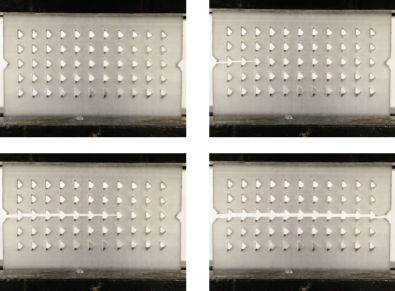
The asymmetry of fracture toughness is demonstrated in a metamaterial consisting of a two-dimensional array of voids shown in Figure 1 and loaded in uniaxial tension. Even though the specimen and loading are symmetric on a scale large compared to that of individual voids (microscale), the crack propagates from left to right indicating that the effective toughness is smaller in one direction compared to that in the other.
To understand this, we numerically compute the effective toughness of the metamaterial following Hossain et al. Hossain et al. (2014). We take a region large compared to the microstructure and rip it apart at a constant macroscopic rate by applying a surfing boundary condition. This is a steadily translating opening displacement imposed on the boundary. Here, we take to be the displacement of a mode-I crack in plane-stress state Zehnder (2012) with steady velocity (See Figure S1 in Supplemental Information (SI)). We compute the fracture process using a phase field method (see Methods) with no restrictions on the crack set: pinning, kinking, branching, distal nucleation are all allowed. We compute the macroscopic driving force on the boundary using the integral Rice (1968). While the integral can be path dependent at the scale of the heterogeneities, it reaches an asymptotic limit for large paths distal from the crack tip; further, this limit is path-independent on paths that are sufficiently large compared to the underlying microstructure and far away from the crack Hsueh and Bhattacharya (2016). The driving force () fluctuates as the fracture process negotiates the microstructure, but eventually reaches a steady pattern. The effective toughness is the maximum of this steady pattern since this is the smallest driving force necessary to drive the crack set macroscopically. The approach has been extensively tested Hossain et al. (2014) and experimentally verified Hsueh et al. (2018); Brodnik et al. (2020) (See Figure S2 in SI). Importantly, the effective toughness depends only on the material and overall direction and is independent of and .
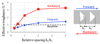
The computed effective toughness of a metamaterial of the type shown in Figure 1 is shown in Figure 2 for various cases (See SI Figure S3 for details). Briefly, the crack propagates intermittantly at the microscale: it is pinned at each inclusion until a higher applied driving force unpins it, following which it jumps to the next inclusion. The effective toughness in the forward direction is significantly lower than that in the backward direction resulting in the asymmetry of toughness. Importantly, both values are larger than that of the base material. Thus, the asymmetry of toughness is not achieved by embrittling the material in one direction, but rather by asymmetrically toughening the material in both directions.
It is known from the study of layered materials that cracks are pinned and have to renucleate at compliant-to-stiff interfaces He and Hutchinson (1989); Hsueh et al. (2018), but not by stiff-to-compliant interfaces. So, at the microscale, the crack can easily enter the inclusion but has difficulty exiting it. In the forward direction, it sees a notch where it can renucleate relatively easily. However, in the backward direction, it sees a flat interface that it has difficulty penetrating. This causes asymmetry while retaining superior toughness in both directions. Designed properly, the asymmetry or difference in effective toughness can be about twice as large as the toughness of the original medium. Finally, the effective toughness in both directions depends on length-scales or spacing, and this is well understood Hossain et al. (2014). Briefly, at very small spacing (smaller than the length-scale of the so-called macroscopic -dominant zone where the macroscopic crack-tip senses and explores the stress field), the crack sees a homogeneous medium and is not pinned. The amount of pinning, and therefore, the effective properties increase with spacing before eventually saturating.
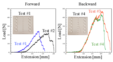
To test this idea, specimens of poly-methyl-methacrylate (PMMA) with a row of triangular voids were loaded on a rail where the loading device seeks to rip the material apart from one end as in the surfing boundary conditions (see Methods and SI Figure S4 for details). It is convenient to work with a specimen with a single row of voids instead of a metamaterial for experimental reasons, but we have verified numerically that the former is representative of the latter. The load-extension curves in both the forward and backward directions are shown in Figure 3. In the forward direction, the force increases steadily till it reaches a critical value at which point a crack nucleates at the notch and rapidly advances to the first inclusion where it is pinned. Subsequently, the crack propagates in an intermittent manner being successively pinned and advancing rapidly to the next inclusion. Each jump is accompanied by a load drop and each pinning phase by a load increase. The propagation in the backward direction is markedly different: the initial crack is nucleated as before but it is strongly pinned by the first inclusion and the load increases to almost twice the value required in the forward direction. At this point, the sample fails catastrophically as a crack nucleates at one of the corners of the inclusion. While the peak load is always higher, the crack path in the backward direction may vary (and is sensitive to the alignment in the loading device). Nonetheless, these data confirm the fracture diode concept, in which the favored fracture direction in this metamaterial design is in the forward orientation.
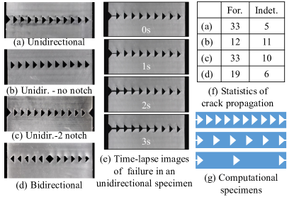
The asymmetry is further established by subjecting a series of metamaterial designs to uniaxial tension tests as in Figure 1. Again, we focus on a single row of voids though it is representative of the metamaterial. A centro-symmetric design would fail with a crack propagating in either direction, but an asymmetric specimen would only fail with the crack propagating in the forward direction. Four designs were 3D printed with an array of triangular inclusions as shown in Figure 4 and tested in uniaxial tension (see Methods and SI Figure S5 for details). Figure 4(e) shows a series of time lapse images of the crack propagating in the forward direction. The figure also shows the statistics of failure: the vast majority of specimens failed with the crack propagating exclusively in the forward direction. Further, fractography (SI Figure S6) indicates that even the local propagation is in the forward direction; the crack nucleates at the tip of the inclusion and propagates locally in the forward direction to the next inclusion. In fact, even in specimens that did not completely fail in the forward direction, local failure occurred in the forward direction. While these results show that the microstructure does generally ‘rectify’ the crack propagation direction, it does not always do so.
In other words, true fracture rectification behavior is somewhat subtle.
To understand this, we study the state of stress in three computational examples shown in Figure 4(g) under uniaxial tension. The specimens have the same width, but have different number of inclusions (Details in SI Figure S7). The first and the last inclusions are at the same location relative to the edge so that the spacing between inclusions change with the number. If the first and last inclusions are close to the edge, the ligaments between the inclusions and edges break early as shown in Figure S7(a). As this stage, we compute the generalized stress intensity factor (GSIF) that determines crack nucleation Tanné et al. (2018) (also SI) at the tip of each inclusion. We find that the GSIF is higher on the first notch from the left, and roughly equal in every other notch (see SI). However, the difference between the GSIF at the first notch and the rest increases with decreasing spacing. In other words, as the spacing between inclusions increases further, the overall direction of crack growth becomes indeterminate; cracks nucleate at inclusion tips but the order in which the ligaments between inclusions break is sensitive to material and manufacturing defects. So, we need small spacing. However, if the spacing becomes too small, the stress fields of the different inclusions overlap and the crack does not see each inclusion individually. Thus, the overall toughness and asymmetry decreases as we saw earlier in Figure 2. Therefore, there is an optimal spacing between the inclusions for sequential cracking. Finally, it is useful to round out the two corners of the inclusion that are distal from the crack path.
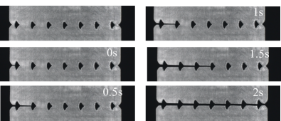
These principles led to the design optimized for topology with a rounded triangular void and spacing to control nucleation, shown in Figure 5 (also SI Figure S8). Twelve specimens were printed and tested. All twelve specimens failed with the crack propagating intermittently – being pinned at an inclusion and then jumping to the next inclusion where it is again pinned – in the forward direction. Snapshots from a representative tensile test are shown in Figure 5. In fact, two of the twelve specimens were pre-cracked at the opposite end with a razor blade, but this did not prevent the crack from propagating in the forward direction.
In summary, in this letter we have established the directional asymmetry or the lack of centro-symmetry in fracture, and more broadly in bulk mechanical properties. We are unaware of any natural materials possessing this asymmetry. Importantly, the asymmetry arises from the enhancement of toughness in one direction rather than by the embrittlement in the other directions. The experiments presented here included a single row of voids, but the idea easily generalizes to a periodic array of 3D-printed partially filled voids Brodnik et al. (2020), inclusions or other asymmetric microstructures. Likewise, directional asymmetry would be preserved in the two- or three-dimensional metamaterials, as noted in Figure 1. However, the design of such microstructures requires one to account for the delicate interplay between macroscopic loading, structural response, the microstructural response and the various length-scales (local and global stress field, nucleation length, etc.).
The observed asymmetry in toughness opens the way for various applications because it enables the control of crack paths and directions. This control can be exploited to build resilience in structures by shielding sensitive components and function by guiding cracks away from critical regions. In other words, we can prescribe the failure path when failure is inevitable. Further, the prescription of the failure path can enhance health-monitoring of structures. The control of crack paths can also enable new functionality by enabling a particular sequence of failure events without careful control of loads.
I Methods
Variational phase-field approach to fracture
Crack propagation in heterogeneous samples is investigated numerically through the variational phase-field fracture approach of Bourdin et al. Bourdin et al. (2000, 2008). An elastic/perfectly brittle material is considered, with isotropic elastic tensor (expressed in terms of the Young’s modulus and Poisson’s ratio ) and critical energy-release rate , occupying a region . In this approach, the crack is regularized on a length-scale by introducing a continuous (damage or fracture) field such that describes the intact material and fracture is represented by regions of width proportional to where transitions from 0 to 1. At each time-step, the state of the material is determined by minimizing the energy functional
| (1) |
under a growth condition to account for the irreversible nature of the fracture process. Above, is the strain associated with the displacement , while is a small residual stiffness introduced for numerical convenience. A finite element discretization at mesh-size leads to a numerical toughness equal to for the intact material Bourdin et al. (2008). This approach has been shown to properly account for crack propagation, nucleation, and re-nucleation in a wide range of sitations, provided that the small parameter be correlated with the crack nucleation threshold Tanné et al. (2018). The fracture problem is solved by alternatively minimizing the total energy functional in Eq. (1) with respect the two state variables and . The constrained minimization with respect to the fracture field is implemented using the variational inequality solvers provided by PETSc Balay et al. (1997, 2019), whereas the minimization with respect to displacement field is a linear problem, solved by using a preconditioned conjugated gradient method. All computations are performed by means of the open source code mef90 Bourdin (2019). The equations are non-dimensionalized and the non-dimensional parameters are chosen to be , , , , , .
Specimen fabrication
The PMMA specimens for the tests in Figure 3 were fabricated from a 3.175mm thick sheet using a Universal ILS9 (Tech-Labs, Katy, TX) laser cutter. The specimen geometry is shown in the SI. The 3D printed specimens were printed using digital light processing (DLP) printing on an Autodesk Ember 3D Printer (Autodesk, San Rafael, CA). Samples were made from commercially available Standard Clear PR48 printing resin, a urethane acrylate photopolymer. For the uniaxial specimens in Figure 4, the gauge length is and the triangle has a base of length and spacings of . The dimensions of the fracture diode in Figure 5 are provided in SI.
Mechanical Testing
We use two different modes of mechanical testing. The first is conventional uniaxial loading where a rectangular specimen is gripped along two edges and a uniform displacement is applied across each edge. These were performed on an Instron 5892 load frame (Instron, Norwood, MA) at a constant displacement rate of and replicates of each sample type were rotated and mirrored randomly to ensure that no bias was introduced due to the innate directionality of the DLP printing process. For each test, the load and displacement were recorded using data from the load cell and the failure behavior of the sample itself was recorded with a Nikon D7500 (Nikon, Tokyo, Japan) digital camera at a rate of 30 frames per second. Loading data and video were synchronized through visible failure events. After testing, video recordings of failure were then reviewed frame-by-frame using the post-production film software DaVinci Resolve (Blackmagic Design, Port Melbourne, Australia) to classify failure based on criteria of forward or indeterminate failure based on behavior predicted by analogous simulations
The second mode of mechanical testing is an unconventional method that seeks to rip a specimen apart from one end using a rail following Hsueh et al. Hsueh et al. (2018) (see SI). The rectangular specimen contains a row of circular holes near two opposing edges. A bushing passes through each hole, and the bushings are guided along a wedge shaped rail system so that pairs of opposing holes are pulled apart sequentially. The wedge-shaped rail has an angle of ) and is loaded using an Instron 5892 load frame at a constant displacement rate of .
This work was conducted while Brodnik and Brach were at Caltech. We are grateful to Paolo Celli and Kevin Korner for their help in preparing the PMMA specimens. We gratefully acknowledge the financial support of the U.S. National Science Foundation (Grant No. DMS-1535083 and 1535076) under the Designing Materials to Revolutionize and Engineer our Future (DMREF) Program. The development of the numerical codes used here was supported in part by the U.S. National Science Foundation DMS-1716763. The numerical simulations were performed at the Caltech high performance cluster supported in part by the Moore Foundation.
References
- Daniel et al. (2004) S. Daniel, S. Sircar, J. Gliem, and M. K. Chaudhury, Langmuir 20, 4085 (2004).
- Khoo and Tseng (2009) H. S. Khoo and F.-G. Tseng, Applied Physics Letters 95, 063108 (2009).
- Shastry et al. (2006) A. Shastry, M. J. Case, and K. F. Böhringer, Langmuir 22, 6161 (2006).
- Sandre et al. (1999) O. Sandre, L. Gorre-Talini, A. Ajdari, J. Prost, and P. Silberzan, Physical Review E 60, 2964 (1999).
- Malvadkar et al. (2010) N. A. Malvadkar, M. J. Hancock, K. Sekeroglu, W. J. Dressick, and M. C. Demirel, Nature Materials , 1 (2010).
- Hancock et al. (2012) M. J. Hancock, K. Sekeroglu, and M. C. Demirel, Advanced Functional Materials 22, 2223 (2012).
- Lu et al. (2018) P. Lu, R. J. K. Wood, M. G. Gee, L. Wang, and W. Pfleging, Tribology Letters 66, 1 (2018).
- Xia et al. (2012) S. Xia, L. Ponson, G. Ravichandran, and K. Bhattacharya, Physical Review Letters 108, 196101 (2012).
- Xia et al. (2013) S. M. Xia, L. Ponson, G. Ravichandran, and K. Bhattacharya, Journal of the Mechanics and Physics of Solids 61, 838 (2013).
- Xia et al. (2015) S. M. Xia, L. Ponson, G. Ravichandran, and K. Bhattacharya, Journal of the Mechanics and Physics of Solids 83, 88 (2015).
- Majumder et al. (2012) A. Majumder, S. Mondal, A. K. Tiwari, A. Ghatak, and A. Sharma, Soft Matter 8, 7228 (2012).
- Hossain et al. (2014) M. Z. Hossain, C. J. Hsueh, B. Bourdin, and K. Bhattacharya, Journal of the Mechanics and Physics of Solids 71, 15 (2014).
- Frenzel et al. (2017) T. Frenzel, M. Kadic, and M. Wegener, Science 358, 1072 (2017).
- Lubensky et al. (2015) T. C. Lubensky, C. L. Kane, X. Mao, A. Souslov, and K. Sun, Reports on Progress in Physics 78, 073901 (2015).
- Kadic et al. (2019) M. Kadic, G. W. Milton, M. Hecke, and M. Wegener, Nature Reviews Physics , 198 (2019).
- Faber and Evans (1983) K. T. Faber and A. G. Evans, Acta Metall Mater 31, 565 (1983).
- He and Hutchinson (1989) M. Y. He and J. W. Hutchinson, International Journal of Solids and Structures 25, 1053 (1989).
- Zehnder (2012) A. T. Zehnder, Fracture Mechanics (Springer Netherlands, Dordrecht, 2012).
- Rice (1968) J. R. Rice, Journal of Applied Mechanics 35, 379 (1968).
- Hsueh and Bhattacharya (2016) C.-J. Hsueh and K. Bhattacharya, Journal of Applied Mechanics 83, 101012 (2016).
- Hsueh et al. (2018) C. J. Hsueh, L. Avellar, B. Bourdin, G. Ravichandran, and K. Bhattacharya, Journal of the Mechanics and Physics of Solids 120, 68 (2018).
- Brodnik et al. (2020) N. R. Brodnik, C.-J. Hsueh, K. T. Faber, B. Bourdin, G. Ravichandran, and K. Bhattacharya, Journal of Applied Mechanics 87 (2020).
- Tanné et al. (2018) E. Tanné, T. Li, B. Bourdin, J. J. Marigo, and C. Maurini, Journal of the Mechanics and Physics of Solids 110, 80 (2018).
- Bourdin et al. (2000) B. Bourdin, G. Francfort, and J.-J. Marigo, Journal of the Mechanics and Physics of Solids 48, 797 (2000).
- Bourdin et al. (2008) B. Bourdin, G. A. Francfort, and J.-J. Marigo, Journal of Elasticity 91, 5 (2008).
- Balay et al. (1997) S. Balay, W. D. Gropp, L. C. McInnes, and B. F. Smith, in Modern Software Tools for Scientific Computing (Birkhäuser Boston, Boston, MA, 1997) pp. 163–202.
- Balay et al. (2019) S. Balay, S. Abhyankar, M. F. Adams, J. Brown, P. Brune, K. Buschelman, L. Dalcin, A. Dener, V. Eijkhout, W. D. Gropp, D. Kaushik, M. G. Knepley, D. A. May, L. C. McInnes, R. T. Mills, T. Munson, K. Rupp, P. Sanan, B. F. Smith, S. Zampini, H. Zhang, and H. Zhang, “PETSc Web page,” (2019).
- Bourdin (2019) B. Bourdin, “mef90/vDef: variational models of defect mechanics,” (2019), available at https://github.com/bourdin/mef90.